EP0321226B1 - Circuit générateur d'un potentiel intermédiaire entre un potentiel d'alimentation et un potentiel de masse - Google Patents
Circuit générateur d'un potentiel intermédiaire entre un potentiel d'alimentation et un potentiel de masse Download PDFInfo
- Publication number
- EP0321226B1 EP0321226B1 EP88311848A EP88311848A EP0321226B1 EP 0321226 B1 EP0321226 B1 EP 0321226B1 EP 88311848 A EP88311848 A EP 88311848A EP 88311848 A EP88311848 A EP 88311848A EP 0321226 B1 EP0321226 B1 EP 0321226B1
- Authority
- EP
- European Patent Office
- Prior art keywords
- potential
- power source
- intermediate potential
- input terminal
- inverting input
- Prior art date
- Legal status (The legal status is an assumption and is not a legal conclusion. Google has not performed a legal analysis and makes no representation as to the accuracy of the status listed.)
- Expired - Lifetime
Links
Images


Classifications
-
- G—PHYSICS
- G11—INFORMATION STORAGE
- G11C—STATIC STORES
- G11C5/00—Details of stores covered by group G11C11/00
- G11C5/14—Power supply arrangements, e.g. power down, chip selection or deselection, layout of wirings or power grids, or multiple supply levels
- G11C5/147—Voltage reference generators, voltage or current regulators; Internally lowered supply levels; Compensation for voltage drops
-
- G—PHYSICS
- G05—CONTROLLING; REGULATING
- G05F—SYSTEMS FOR REGULATING ELECTRIC OR MAGNETIC VARIABLES
- G05F1/00—Automatic systems in which deviations of an electric quantity from one or more predetermined values are detected at the output of the system and fed back to a device within the system to restore the detected quantity to its predetermined value or values, i.e. retroactive systems
- G05F1/10—Regulating voltage or current
- G05F1/46—Regulating voltage or current wherein the variable actually regulated by the final control device is DC
- G05F1/461—Regulating voltage or current wherein the variable actually regulated by the final control device is DC using an operational amplifier as final control device
-
- G—PHYSICS
- G05—CONTROLLING; REGULATING
- G05F—SYSTEMS FOR REGULATING ELECTRIC OR MAGNETIC VARIABLES
- G05F3/00—Non-retroactive systems for regulating electric variables by using an uncontrolled element, or an uncontrolled combination of elements, such element or such combination having self-regulating properties
- G05F3/02—Regulating voltage or current
- G05F3/08—Regulating voltage or current wherein the variable is DC
- G05F3/10—Regulating voltage or current wherein the variable is DC using uncontrolled devices with non-linear characteristics
- G05F3/16—Regulating voltage or current wherein the variable is DC using uncontrolled devices with non-linear characteristics being semiconductor devices
- G05F3/20—Regulating voltage or current wherein the variable is DC using uncontrolled devices with non-linear characteristics being semiconductor devices using diode- transistor combinations
- G05F3/24—Regulating voltage or current wherein the variable is DC using uncontrolled devices with non-linear characteristics being semiconductor devices using diode- transistor combinations wherein the transistors are of the field-effect type only
Definitions
- This invention concerns an intermediate potential generation circuit for generating a potential intermediate between a power source potential Vcc and ground potential in a semiconductor chip, such as a LSI chip. More particularly, this invention concerns an intermediate potential generation circuit which has a large current driving capacity and a low power consumption.
- FIGS.1 (a) to (c) Conventional intermediate circuits as shown in FIGS.1 (a) to (c) are used to generate an intermediate potential within a LSI chip, as disclosed in EP-A- 0,205,10H.
- an intermediate potential VM is achieved at node 2 by dividing a power source potential Vcc supplied to a terminal 1 by resistors R1 and R2 .
- an intermediate potential VM is achieved at node 4 by dividing a power source potential Vcc supplied to a terminal 3 by a resistor R3 and a series connection of diodes D1 to D3 .
- the intermediate voltage VM is maintained within a rage determined by the reference potentials at nodes N2 and N3 .
- the potential VN2 at node N2 is higher than the potential VN1 at the node N1 by the threshold voltage VTN3 of an N -channel MOS transistor M3.
- the potential VN2 is expressed as follows.
- VN2 VN1 + VTN3 (1)
- the potential VN3 at the node N3 is lower than the potential VN1 by the absolute value VTP4 of the threshold voltage of a P -channel MOS transistor M4 .
- VTP4 absolute value of the threshold voltage of a P -channel MOS transistor M4 .
- VN3 VN1 - VTP4 (2)
- the MOS transistor M1 changes to a conductive state, and the intermediate potential VM is raised.
- the intermediate potential VM is higher than the second reference potential VN3 by the absolute value VTP2 of the threshold voltage of a P -channel MOS transistor M2 , the MOS transistor M2 becomes conductive to lower the intermediate potential VM .
- the intermediate potential VM is maintained within a range expressed as follows. ⁇ VN1 - ( VTN1 - VTN3 ) ⁇ ⁇ VM ⁇ VN1 + ( VTP2 - VTP4 ) ⁇ (4)
- the threshold voltages VTN1 larger than the VTN3 and by setting the VTN2 larger then the VTP4 , the intermediate potential VM is maintained within a range ⁇ V as shown in FIG.2 .
- the range ⁇ V is expressed as follows.
- ⁇ V ⁇ VTN + ⁇ VTP (5) wherein the ⁇ VTN is ( VTN1 - VTN3 ), and the ⁇ VTP is ( VTP2 - VTP4 ).
- the intermediate potential VM is maintained within a predetermined allowed range ⁇ V .
- the intermediate potential VM is within the range ⁇ V , no through current flows between the terminal 6 and ground since both the MOS transistors M1 and M2 are nonconductive, and in high impedance state.
- MOS transistors of large dimension to increase the current driving capacity.
- FIGS. 1 ( a ) and ( b ) are simple. However, with these constructions it is impossible both to reduce power consumption and increase the driving capacity at the same time. Namely, in the case where a large capacitor is connected to the output terminals 2 and 4 , a large current driving capacity is required to bring back the intermediate potential VM to the predetermined value determined by the resistance value, from the shifted potential level. When the resistance values of the resistors R1 , R2 and R3 are reduced to increase the current driving capacity so as to obtain rapid recovery of the intermediate potential VM , the current which flows through the resistors increases, and the power consumption is increased.
- the gate to source voltages of the MOS transistors M1 and M2 are difference voltages between the intermediate potential VM and the first and the second reference potentials N2 and VN3 . Therefore, in the condition where the intermediate potential VM is slightly out of the allowed range ⁇ V , the transistors M1 and M2 operate in saturation condition. Thus, the current driving capacities of the transistors M1 and M2 are not so large, as shown in FIG.2 , since the respective gate to source voltage supplied to the transistors are relatively small, Therefore, even if MOS transistors having large dimension are used for the MOS transistors M1 and M2 to increase the driving capacity, these transistors are not used effectively to increase the current driving capacity. Thus, the circuit of FIG.1 ( c ) is inadequate in the case where fast response or rapid recovery is required.
- an object of this invention is to provide a new and improved intermediate potential generation circuit of low power consumption yet having increased current driving capacity.
- a novel intermediate potential generation circuit for outputting an intermediate potential responsive to power source potential, including: reference potential generating means for generating first and second reference potentials responsive to the power source potential, where the first reference potential is lower than that the second reference potential; comparing means responsive to the first reference potential, the second reference potential and the intermediate potential for producing a first control signal when the intermediate potential is lower than the first reference potential, and for producing a second control signal when the intermediate potential is higher than the second reference potential; first circuit means responsive to the first control signal for raising the intermediate potential; and second circuit means responsive to the second control signal for lowering the intermediate potential.
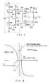
- FIG.3 there is illustrated a preferred embodiment of this invention.
- a reference potential generating circuit 40 for generating first and second reference potentials responsive to a power source potential.
- the generating circuit 40 includes resistors R6 , R7 , R8, R9, P -channel MOS transistors M6, M8 and N -channel MOS transistors M5 and M7.
- the resistor R6 , the MOS transitors M5 and M6 and the resistor R7 are serially connected between a terminal 10 supplied with a power source potential Vcc and ground.
- the gate electrode and the drain electrodes of the MOS transistor M5 are connected in common.
- the gate electrode and the drain electrode of the MOS transistor M6 are connected in common.
- the MOS transistor M7 and the resistor R8 are connected in series between a terminal 11 supplied with the power source potential Vcc and ground.
- the connection between the resistor R8 and the source electrode of the MOS transistor M7 forms a node N7 .
- the gate electrode of the MOS transistor M7 is connected to a node N5 .
- the resistor R9 and the MOS transistor M8 are connected in series between a terminal 12 supplied with the power source potential Vcc and ground.
- the connection between the resistor R9 and the source electrode of the MOS transistor M8 forms a node N8 .
- the gate electrode of the transistor M8 is connected to the node N6 .
- the threshold voltage of the MOS transistor M5 is made smaller than that of the MOS transistor M7
- the absolute value of the threshold voltage of the MOS transistor M6 is made smaller than that of the MOS transistor M8 , by taking some measures.
- the absolute value of the threshold voltage of the MOS transistor M8 is made larger than that of the MOS transistor M6 by using the following techniques, for example:
- the reference potential generating means 40 generates first and second reference potentials at nodes N7 and N8 .
- VN5 VN4 + VTN5 (6)
- VN4 the potential at node N4
- VTN5 the threshold voltage of the N -channel MOS transistor M5 .
- the potential at node N6 is lower than the potential VN4 at node N4 by the absolute value VTP6 of the threshold voltage of the P -channel MOS transistor M6 .
- the potential VN6 at the node N6 is expressed as follows.
- VN6 VN4 - VTP6 (7)
- the potential VN7 at node N7 is lower than the potential VN5 by the threshold voltage of the N -channel MOS transistor M7 .
- the potential VN7 namely the first reference potential, is expressed as follows.
- VN7 VN5 - VTN7 (8)
- VN8 VN6 + VTP8 (9)
- VN7 VN4 - ( VTN7 - VTN5 ) (10)
- VN8 VN4 + ( VTP8 - VTP6 ) (11)
- the equations (10) and (11) can be rewritten as follows.
- VN7 VN4 - ⁇ VTN (12)
- VN8 VN4 + ⁇ VTP (13) wherein the ⁇ VTN is ( VTN7 - VTN5 ), and the ⁇ VTP is (VTP8 - VTP6 ).
- the first reference potential VN7 can be set lower than the second reference potential VN8 .
- comparing means responsive to the first and the second reference potentials and output, namely the intermediate potential VM .
- the comparing means is 41 .
- the comparating means includes first comparator CMP1 and second comparator CMP2 .
- the non-inverting input terminal (+) of the first comparator CMP1 is connected to the node N7 and receives the first reference potential VN7 .
- the inverting input terminal (-) of the second comparator CMP2 is connected to the node N8 , and receives the second reference potential VN8 .
- Both of the first and the second comparators CMP1 and CMP2 are biased with the power source potential Vcc and ground.
- the first circuit means is an N -channel MOS transistor M9 .
- the gate electrode of the MOS transistor M9 is connected to the output of the first comparator CMP1 , and the drain electrode thereof is connected to a terminal 13 supplied with the power source potential Vcc .
- the source electrode of the MOS transistor M9 is connected to an output terminal 14 .
- the second circuit means is an N -channel MOS transistor M10 .
- the gate electrode of the MOS transistor M10 is connected to the output of the second comparator CMP2 , and the source electrode thereof is connected to ground.
- the drain electrode of the transitor M10 is connected to the output terminal 14 .
- the inverting input terminal (-) of the comparator CMP1 is connected to the output terminal 14 , and receives the output voltage, namely an intermediate voltage VM .
- the non-inverting input terminal (+) of the comparator CMP2 is connected to the output terminal 14 , and receives the intermediate voltage VM .
- the comparator circuit CMP1 When the intermediate potential VM is lower than the first reference potential VN7 , the comparator circuit CMP1 outputs a potential which is equal to the power potential Vcc , as a control signal. Thus, the N -channel MOS transistor M9 changes to a conductive state. Thus, the output terminal 14 is charged, and the intermediate potential VM is raised. On the contrary, the intermediate voltage VM exceeds the first reference potential VN7 , the comparator CMP1 outputs a potential which is equal to ground level, namely 0 volt. Thus, the MOS transistor M9 changes to a non-conductive state.
- the second comparator CMP2 when the intermediate potential VM is higher than the second reference potential VN8 , the second comparator CMP2 outputs a potential which is equal to Vcc , and makes the N -channel MOS transistor M10 conductive. Thus, a discharging is performed to lower the intermediate potential VM at the output terminal 14 .
- the second comparator CMP2 when the intermediate potential VM becomes lower than the second reference potential VN8 , the second comparator CMP2 outputs a potential which is equal to the ground level, namely 0 volt. Thus, the MOS transistor M10 changes to a non-conductive state, and the discharge is stopped.
- the intermediate potential VM is maintained within an allowed range expressed as follows.
- the gate potential supplied by either comparator CMP1 or CMP2 is equal to the power source potential Vcc and sufficiently high.
- the gate to source voltage of the MOS transistors M9 or M10 when in the conductive state, is sufficiently large.
- the through current between the terminal 10 and ground, and between the terminals 11 , 12 and ground can be reduced to a sufficiently small value.
- the power consumption due to the reference potential generating means 40 can be restricted to sufficiently small value.
- FIG.4 shows the characteristic of the embodiment of FIG.3 .
- the gate potential supplied to the MOS transistor M9 or M10 is Vcc and sufficiently high, when the intermediate potential VM is out of the allowed range between the first and the second reference potentials VN7 and VN8 , Therefore, the current driving capacity, namely the current I , is sufficiently large compared with that of FIG.2 , as shown in FIG.4 ,
- the MOS transistor M9 or M10 is biased with large gate to source voltage.
- the inermediate potential VM is rapidly pulled into the allowed range or a high impedance range ⁇ V due to the large current driving capacity of the MOS transistors M9 and M10 .
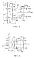
- FIG.5 is a circuit diagram of another embodiment of this invention.
- the reference potential generating circuit 40 has the same construction as that of the embodiment of FIG.3 .
- the difference with respect to the embodiment of FIG.3 is a construction of comparing means 42 and the conductivity type of the MOS transistors which supply the output of the comparing means 42 .
- the conductivity type of the MOS transistor M15 connected between the terminal 15 and the output terminal 16 is P -type, in contrast with that the transistor M9 is N -type in FIG.3 .
- the comparing means 42 includes comparators CMP2 and CMP3 .
- the inverting input terminal (-) of the comparator CMP3 is connected to the node N7 and receives the first reference potential VN7 .
- the non-inverting input terminal (+) of the comparator CMP3 is connected to an output terminal 16 , and receives an intermediate potential VM .
- the operation of the circuit of FIG.5 is as follows.
- the comparor CMP3 When the intermediate potential VM is lower than the first reference potential VN7 , the comparor CMP3 outputs a potential which is equal to the ground level, namely 0 volt, and makes the P -channel MOS transistor M15 conductive.
- the output terminal 16 is raised to the intermediate potential VM .
- the comparator CMP3 outputs a potential which is equal to the power source potential Vcc and makes the P -channel MOS transistor M15 non-conductive.
- the comparator circuit CMP2 When the intermediate potential VM is higher than the second reference potential VN8 , the comparator circuit CMP2 outputs a potential which is equal to Vcc and makes the N -channel MOS transistor M10 conductive. Thus, the potential at the output terminal 16 is lowered. On the contrary, when the intermediate potential VM becomes lower than the second reference potential VN8 , the comparator CMP2 outputs a potential which is equal to the ground level, namely 0 volt, to make the N -channel MOS transistor M10 non-conductive. In this way, the intermediate potential VM is maintained within the range between the first and the second reference potentials, as shown in FIG.4 .
- the gate potential becomes Vcc or 0 volt to control the conductivity state of the transistor M10 or M15 , even if the intermediate potential VM is only slightly out of the allowed range slightly.
- the transistors M10 and M15 are conrolled with sufficiently large gate to source voltage, and the transistor M15 operatates in a non-saturation state with large current driving capacity
- FIG.6 is a circuit diagram of further embodiment of the present invention.
- the conductivity type of the MOS transistor connected between the output terminal 18 and ground is changed to P -type with respect to the embodiment of FIG.3 .
- the construction of the comparing means 43 is changed.
- the comparating means 43 includes comparators CMP1 and CMP6 .
- the non-inverting input terminal (+) of the comparator CMP6 is connected to the node N8 , and receives the second reference potential VN8 .
- the inverting input terminal (-) of the comparator CMP6 is connected to the output terminal 18 , and receives the intermediate potential VM .
- the comparator CMP1 when the intermediate potential VM is lower than the first reference potential VN7 , the comparator CMP1 outputs a control signal of Vcc level to make the MOS transistor M9 conductive and to rise the intermediate potential VM .
- the CMP1 When the intermediate potential VM exceeds the first reference potential VN7 , the CMP1 outputs a control signal of 0 volt to make the transistor M9 non-conductive and to stop the charging through the transistor M9 .
- the comparator CMP6 When the intermediate potential VM is higher than the second reference potential VN8 , the comparator CMP6 outputs a control signal of 0 volt to make the transistor M22 conductive and to lower the intermediate potential VM . When the intermediate potential VM becomes lower than the second reference potential VN8 , the CMP6 outputs a control signal at the Vcc level to make the M22 non-conductive. In this way, the intermediate potential VM is maintained within the range determined by the first and the second reference potentials VN7 and VN8 .
- FIG.7 is a circuit diagram of still further embodiment of the present invention.
- the conductivity type of the MOS transistors M15 and M22 is P -type in contrast with the N -type MOS transistors M9 and M10 in the embodiment of FIG.3 .
- the comparing means 44 includes comparators CMP3 and CMP6 .
- the inverting input terminal (-) of the comparator CMP3 is connected to the node N7 and receives the first reference potential VN7 .
- the non-inverting input terminal (+) of the comparator CMP3 is connected to the output terminal 20 and receives the intermediate potential VM .
- the non-inverting input terminal (+) of the comparator CMP6 is connected to the node N8 and receives the second reference potential VN8 .
- the inverting input terminal (-) of the comparator CM6 is connected to the output terminal 20 to receive the intermediate potential VM .
- the operation is as follows.
- the comparator CMP3 When the intermediate potential VM is lower than the first reference potential VN7 , the comparator CMP3 outputs a control signal of 0 volt to put the P -channel MOS transistor M15 in the conductive state. Then the output terminal 20 is charged to rise the potential VM .
- the comparator CMP3 When the interdediate potential VM exceeds the first reference potential VN7 the comparator CMP3 outputs a control signal of level Vcc to make the transistor M15 non-conductive.
- the comparator CMP6 When the intermediate potential VM is higher than the second reference potential VN8 , the comparator CMP6 outputs a control signal of 0 volt to make the MOS transistor M22 conductive. Thus, the intermediate potential at the output terminal 20 is lowered due to the discharge through the MOS transistor M22 . On the contrary, when the intermediate potential VM becomes lower than the second reference potential VN8 , the comparator CMP6 outputs a control signal at the Vcc level to make the MOS transistor M22 non-conductive. In this way, the intermediate potential VM is maintained within the range between the first and the second reference potentials VN7 and VN8 .
- FIG.8 is a circuit diagram of another embodiment of the present invention.
- the reference potential generating means 50 is composed of resistors R22 , R23 , R24 and R25 which are connected in series between the terminal 21 supplied with the power source potential Vcc and ground. By dividing the power source potential Vcc , first reference potential VN7 which is lower than the second reference potential VN8 is achieved. The operation of this embodiment is same to that of the embodiment of FIG.3 . Thus, it is omitted.
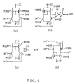
- FIGS.9 ( a ) to 9 ( d ) are circuit diagrams which are applicable to the comparator in the prescribed embodiments.
- the comparator of FIG.9 ( a ) is a basic construction, and includes N -channel MOS transistors M100 and P -channel MOS transistors M200 . The operation of the circuit is omitted as it is well known.
- FIG.9 ( c ) an inverter circuit I3 is added and the inverting input terminal and the non-inverting input terminal are reversed with respect to the circuit of FIG.9 ( a ).
- FIG.9 ( d ) P -channel MOS transistors M200 are used to receive the input signals, and N -channel MOS transistors M100 are used as load. Needless to say, some modification by adding the inverter circuits like FIGS.9 ( b ) and ( c ) is possible, similarly.
- a MOS transistor controlled by control signal ⁇ may be connected between the comparator circuit and the power source terminal to only enable the operation of the comparator circuit.
- MOS transistors are used to charge or discharge the output terminal.
- bipolar transistors instead of the MOS transistors.
- a load MOS transistor which can be considered as a resistor can be used as a resistor in the reference potential generating means in respective embodiment, as well known.
Landscapes
- Engineering & Computer Science (AREA)
- Physics & Mathematics (AREA)
- Power Engineering (AREA)
- Microelectronics & Electronic Packaging (AREA)
- Electromagnetism (AREA)
- General Physics & Mathematics (AREA)
- Radar, Positioning & Navigation (AREA)
- Automation & Control Theory (AREA)
- Nonlinear Science (AREA)
- Dram (AREA)
- Control Of Electrical Variables (AREA)
- Semiconductor Integrated Circuits (AREA)
- Continuous-Control Power Sources That Use Transistors (AREA)
- Amplifiers (AREA)
Claims (11)
- Circuit de génération de potentiel intermédiaire émettant en sortie au niveau d'un noeud de sortie (14, 16, 18, 20, 23) un potentiel intermédiaire (VM) qui est intermédiaire entre un premier potentiel d'alimentation (VCC, GND) et un second potentiel d'alimentation, comprenant:
un moyen de génération de potentiel de référence (40, 50) pour générer des premier et second potentiels de référence en réponse aux premier et second potentiels d'alimentation, dans lequel le premier potentiel de référence est inférieur au second potentiel de référence,
caractérisé par:
un moyen de comparaison (41, 42, 43, 44, 51) sensible au premier potentiel de référence, au second potentiel de référence et au potentiel intermédiaire pour produire un premier signal de commande lorsque le potentiel intermédiaire est inférieur au premier potentiel de référence et pour produire un second signal de commande lorsque le potentiel intermédiaire est supérieur au second potentiel de référence;
un premier moyen de circuit (M9, M15) comportant une sortie connectée audit noeud de sortie et une entrée sensible au premier signal de commande pour augmenter le potentiel intermédiaire; et
un second moyen de circuit (M10, M22) comportant une sortie connectée audit noeud de sortie et une entrée sensible au second signal de commande pour abaisser le potentiel intermédiaire au niveau dudit noeud de sortie. - Circuit de génération de potentiel intermédiaire selon la revendication 1, dans lequel la différence de potentiel entre l'entrée et la sortie de l'un respectif desdits premier et second moyens de circuit de sortie suite à la production de l'un respectif desdits premier et second signaux de commande est la différence entre l'un desdits potentiels pris parmi lesdits potentiels d'alimentation et ledit potentiel intermédiaire.
- Circuit de génération de potentiel intermédiaire selon la revendication 1, dans lequel le moyen de comparaison (41, 42, 43, 44, 51) comprend:
des premier et second comparateurs (CMP1, CMP2, CMP3, CMP6) sensibles au potentiel d'alimentation, dans lequel le premier comparateur émet en sortie le premier signal de commande en réponse au premier potentiel de référence et au potentiel intermédiaire et le second comparateur émet en sortie le second signal de commande en réponse au second potentiel de référence et au potentiel intermédiaire. - Circuit de génération de potentiel intermédiaire selon la revendication 1, dans lequel les premier et second moyens de circuit incluent chacun un transistor MOS (métal-oxyde-semiconducteur) à canal P (M9, M10) comportant une électrode de grille qui se voit appliquer l'un respectif des premier et second signaux de commande et un élément sélectionné pris parmi un drain et une source connecté audit noeud de sortie.
- Circuit de génération de potentiel intermédiaire selon la revendication 4, dans lequel le potentiel grille-source des transistors MOS à canal P desdits premier et second moyens de circuit, suite à l'application de l'un respectif desdits premier et second signaux de commande auxdits transistors MOS à canal P, est la différence entre l'un desdits potentiels d'alimentation et ledit potentiel intermédiaire.
- Circuit de génération de potentiel intermédiaire selon la revendication 1, dans lequel le moyen de génération de potentiel de référence comprend:
une première voie entre le premier potentiel d'alimentation et le second potentiel d'alimentation, incluant:
une première résistance (R6) comportant une première extrémité qui se voit appliquer le premier potentiel d'alimentation, et une seconde extrémité;
un premier transistor MOS (M5) d'un premier type de conductivité comportant une électrode de grille et une électrode de drain connectées à l'autre extrémité de la première résistance et une électrode de source;
un second transistor MOS (M6) d'un second type de conductivité comportant une électrode de source connectée à l'électrode de source du premier transistor MOS ainsi qu'une électrode de grille et qu'une électrode de drain connectées en commun; et
une seconde résistance (R7) comportant une première extrémité connectée à la connexion commune des électrodes de grille et de drain du second transistor MOS et une seconde extrémité qui se voit appliquer le second potentiel d'alimentation;
une seconde voie entre le premier potentiel d'alimentation et le second potentiel d'alimentation incluant:
un troisième transistor MOS (M7) d'un premier type de conductivité comportant une électrode de drain qui se voit appliquer le premier potentiel d'alimentation et une électrode de grille connectée à l'électrode de drain du premier transistor MOS, et une électrode de source; et
une troisième résistance (R8) comportant une première extrémité connectée à l'électrode de source du troisième transistor MOS et une seconde extrémité qui se voit appliquer le second potentiel d'alimentation; et
une troisième voie entre le premier potentiel d'alimentation et le second potentiel d'alimentation, incluant:
une quatrième résistance (R9) comportant une première extrémité qui se voit appliquer le premier potentiel d'alimentation et une seconde extrémité; et
un quatrième transistor MOS (M8) d'un second type de conductivité comportant une électrode de grille connectée à l'électrode de drain du second transistor MOS, une électrode de source connectée à la seconde extrémité de la quatrième résistance et une électrode de drain qui se voit appliquer le second potentiel d'alimentation. - Circuit de génération de potentiel intermédiaire selon la revendication 3, dans lequel le premier comparateur comporte une borne d'entrée de non inversion qui se voit appliquer le premier potentiel de référence et une borne d'entrée d'inversion qui se voit appliquer le potentiel intermédiaire et le second comparateur comporte une borne d'entrée d'inversion qui se voit appliquer le second potentiel de référence et une borne d'entrée de non inversion qui se voit appliquer le potentiel intermédiaire.
- Circuit de génération de potentiel intermédiaire selon la revendication 3, dans lequel le premier comparateur comporte une borne d'entrée d'inversion qui se voit appliquer le premier potentiel de référence et une borne d'entrée de non inversion qui se voit appliquer le potentiel intermédiaire et le second comparateur comporte une borne d'entrée d'inversion qui se voit appliquer le second potentiel de référence et une borne d'entrée de non inversion qui se voit appliquer le potentiel intermédiaire.
- Circuit de génération de potentiel intermédiaire selon la revendication 3, dans lequel le premier comparateur (CMP1) comporte une borne d'entrée de non inversion qui se voit appliquer le premier potentiel de référence et une borne d'entrée d'inversion qui se voit appliquer le potentiel intermédiaire et le second comparateur (CMP2) comporte une borne d'entrée de non inversion qui se voit appliquer le second potentiel de référence et une borne d'entrée d'inversion qui se voit appliquer le potentiel intermédiaire.
- Circuit de génération de potentiel intermédiaire selon la revendication 3, dans lequel le premier comparateur (CMP3) comporte une borne d'entrée d'inversion qui se voit appliquer le premier potentiel de référence et une borne d'entrée de non inversion qui se voit appliquer le potentiel intermédiaire et le second comparateur (CMP6) comporte une borne d'entrée de non inversion qui se voit appliquer le second potentiel de référence et une borne d'entrée d'inversion qui se voit appliquer le potentiel intermédiaire.
- Circuit de génération de potentiel intermédiaire selon la revendication 3, dans lequel le moyen de génération de potentiel de référence inclut une pluralité de résistances (R22, R23, R24, R25) connectées en série entre les premier et second potentiels d'alimentation.
Applications Claiming Priority (2)
| Application Number | Priority Date | Filing Date | Title |
|---|---|---|---|
| JP320423/87 | 1987-12-18 | ||
| JP62320423A JPH0690655B2 (ja) | 1987-12-18 | 1987-12-18 | 中間電位発生回路 |
Publications (2)
| Publication Number | Publication Date |
|---|---|
| EP0321226A1 EP0321226A1 (fr) | 1989-06-21 |
| EP0321226B1 true EP0321226B1 (fr) | 1993-06-16 |
Family
ID=18121291
Family Applications (1)
| Application Number | Title | Priority Date | Filing Date |
|---|---|---|---|
| EP88311848A Expired - Lifetime EP0321226B1 (fr) | 1987-12-18 | 1988-12-14 | Circuit générateur d'un potentiel intermédiaire entre un potentiel d'alimentation et un potentiel de masse |
Country Status (5)
| Country | Link |
|---|---|
| US (1) | US4906914A (fr) |
| EP (1) | EP0321226B1 (fr) |
| JP (1) | JPH0690655B2 (fr) |
| KR (1) | KR920001634B1 (fr) |
| DE (1) | DE3881850T2 (fr) |
Families Citing this family (42)
| Publication number | Priority date | Publication date | Assignee | Title |
|---|---|---|---|---|
| JPH0690653B2 (ja) * | 1988-12-21 | 1994-11-14 | 日本電気株式会社 | トランジスタ回路 |
| US4958093A (en) * | 1989-05-25 | 1990-09-18 | International Business Machines Corporation | Voltage clamping circuits with high current capability |
| US4943945A (en) * | 1989-06-13 | 1990-07-24 | International Business Machines Corporation | Reference voltage generator for precharging bit lines of a transistor memory |
| EP0411201A1 (fr) * | 1989-08-04 | 1991-02-06 | Siemens Aktiengesellschaft | Générateur de potentiel dans un circuit intégré de mémoire semi-conductrice |
| FR2656174B1 (fr) * | 1989-12-15 | 1995-03-17 | Bull Sa | Procede et dispositif de compensation de la derive en courant dans un circuit integre mos, et circuit integre en resultant. |
| US5087834A (en) * | 1990-03-12 | 1992-02-11 | Texas Instruments Incorporated | Buffer circuit including comparison of voltage-shifted references |
| USRE40552E1 (en) | 1990-04-06 | 2008-10-28 | Mosaid Technologies, Inc. | Dynamic random access memory using imperfect isolating transistors |
| US5212440A (en) * | 1990-05-14 | 1993-05-18 | Micron Technology, Inc. | Quick response CMOS voltage reference circuit |
| US5103157A (en) * | 1990-07-10 | 1992-04-07 | National Semiconductor Corp. | Common emitter amplifiers operating from a multiplicity of power supplies |
| US5027053A (en) * | 1990-08-29 | 1991-06-25 | Micron Technology, Inc. | Low power VCC /2 generator |
| KR920010633A (ko) * | 1990-11-30 | 1992-06-26 | 김광호 | 반도체 메모리 장치의 기준전압 발생회로 |
| JPH04255008A (ja) * | 1991-02-06 | 1992-09-10 | Nec Ic Microcomput Syst Ltd | 電源回路 |
| US5233289A (en) * | 1991-04-23 | 1993-08-03 | Harris Corporation | Voltage divider and use as bias network for stacked transistors |
| US5187429A (en) * | 1992-02-20 | 1993-02-16 | Northern Telecom Limited | Reference voltage generator for dynamic random access memory |
| US5302888A (en) * | 1992-04-01 | 1994-04-12 | Texas Instruments Incorporated | CMOS integrated mid-supply voltage generator |
| JP3381937B2 (ja) * | 1992-05-22 | 2003-03-04 | 株式会社東芝 | 中間電位発生回路 |
| JP3207680B2 (ja) * | 1994-08-30 | 2001-09-10 | 株式会社東芝 | 半導体集積回路 |
| DE69514791T2 (de) | 1995-07-24 | 2000-07-20 | Stmicroelectronics S.R.L., Agrate Brianza | Flash-EEPROM mit onchip-Löschung-Source-Spannungsgenerator |
| EP0757356B1 (fr) * | 1995-07-31 | 2001-06-06 | STMicroelectronics S.r.l. | Flash EEPROM avec temps de décharge contrôlé des tensions de lignes de mot et de la source après l'effaçement |
| JP2806324B2 (ja) * | 1995-08-25 | 1998-09-30 | 日本電気株式会社 | 内部降圧回路 |
| DE69513658T2 (de) * | 1995-09-29 | 2000-05-31 | Stmicroelectronics S.R.L., Agrate Brianza | Spannungsregler für nichtflüchtige, elektrisch programmierbare Halbleiterspeicheranordnungen |
| JPH09162713A (ja) * | 1995-12-11 | 1997-06-20 | Mitsubishi Electric Corp | 半導体集積回路 |
| JP3022815B2 (ja) * | 1997-07-24 | 2000-03-21 | 日本電気アイシーマイコンシステム株式会社 | 中間電位生成回路 |
| US5910726A (en) * | 1997-08-15 | 1999-06-08 | Motorola, Inc. | Reference circuit and method |
| US5959444A (en) * | 1997-12-12 | 1999-09-28 | Micron Technology, Inc. | MOS transistor circuit and method for biasing a voltage generator |
| JP3849835B2 (ja) | 1999-06-23 | 2006-11-22 | 株式会社ルネサステクノロジ | 半導体集積回路装置 |
| KR100323379B1 (ko) * | 1999-12-29 | 2002-02-19 | 박종섭 | 워드라인 전압 레귤레이션 회로 |
| US6400126B1 (en) * | 1999-12-30 | 2002-06-04 | Volterra Semiconductor Corporation | Switching regulator with multiple power transistor driving voltages |
| JP2002258955A (ja) | 2001-02-27 | 2002-09-13 | Toshiba Corp | 半導体装置 |
| KR100762873B1 (ko) * | 2003-06-10 | 2007-10-08 | 주식회사 하이닉스반도체 | 내부 전압 발생기 |
| TWI355792B (en) * | 2003-08-29 | 2012-01-01 | Rohm Co Ltd | Power supply and electronic device having same |
| DE102004043034A1 (de) * | 2004-09-06 | 2006-03-09 | Infineon Technologies Ag | Integrierte Schaltung zur Regelung eines Spannungsgenerators |
| US7594127B2 (en) * | 2004-11-29 | 2009-09-22 | Marvell World Trade Ltd. | Low voltage logic operation using higher voltage supply levels |
| KR100688539B1 (ko) * | 2005-03-23 | 2007-03-02 | 삼성전자주식회사 | 내부전압 발생기 |
| KR100713083B1 (ko) * | 2005-03-31 | 2007-05-02 | 주식회사 하이닉스반도체 | 내부전원 생성장치 |
| KR100794994B1 (ko) * | 2006-04-06 | 2008-01-16 | 주식회사 하이닉스반도체 | 내부전압 발생회로 |
| JP4822941B2 (ja) * | 2006-06-12 | 2011-11-24 | 株式会社東芝 | 電源電圧制御回路および半導体集積回路 |
| KR100838379B1 (ko) * | 2006-09-29 | 2008-06-13 | 주식회사 하이닉스반도체 | 반도체 메모리 장치 |
| US7529135B2 (en) | 2006-12-28 | 2009-05-05 | Sandisk Corporation | Apparatus for controlling bitline bias voltage |
| WO2008082894A1 (fr) * | 2006-12-28 | 2008-07-10 | Sandisk Corporation | Commande de tension de polarisation de ligne de bits |
| KR101226275B1 (ko) * | 2011-02-28 | 2013-01-25 | 에스케이하이닉스 주식회사 | 내부전압생성회로 |
| JP6744604B2 (ja) * | 2016-07-22 | 2020-08-19 | ザインエレクトロニクス株式会社 | 入力装置 |
Family Cites Families (9)
| Publication number | Priority date | Publication date | Assignee | Title |
|---|---|---|---|---|
| JPS57157313A (en) * | 1981-03-23 | 1982-09-28 | Nec Corp | Integrated semiconductor device |
| JPS57157315A (en) * | 1981-03-24 | 1982-09-28 | Nec Corp | Intermediate voltage generating circuit |
| US4663584B1 (en) * | 1985-06-10 | 1996-05-21 | Toshiba Kk | Intermediate potential generation circuit |
| US4788455A (en) * | 1985-08-09 | 1988-11-29 | Mitsubishi Denki Kabushiki Kaisha | CMOS reference voltage generator employing separate reference circuits for each output transistor |
| IT1185935B (it) * | 1985-09-18 | 1987-11-18 | Sgs Microelettronica Spa | Stradio di uscita cmos a grande escursione di tensione e con stabilizzazione della corrente di rifoso |
| JPS62188255A (ja) * | 1986-02-13 | 1987-08-17 | Toshiba Corp | 基準電圧発生回路 |
| JPH07113862B2 (ja) * | 1987-02-27 | 1995-12-06 | 沖電気工業株式会社 | 基準電圧発生回路 |
| JPH0679263B2 (ja) * | 1987-05-15 | 1994-10-05 | 株式会社東芝 | 基準電位発生回路 |
| US4837459A (en) * | 1987-07-13 | 1989-06-06 | International Business Machines Corp. | CMOS reference voltage generation |
-
1987
- 1987-12-18 JP JP62320423A patent/JPH0690655B2/ja not_active Expired - Lifetime
-
1988
- 1988-12-14 DE DE88311848T patent/DE3881850T2/de not_active Expired - Fee Related
- 1988-12-14 EP EP88311848A patent/EP0321226B1/fr not_active Expired - Lifetime
- 1988-12-16 US US07/285,755 patent/US4906914A/en not_active Expired - Lifetime
- 1988-12-16 KR KR1019880016804A patent/KR920001634B1/ko not_active Expired
Also Published As
| Publication number | Publication date |
|---|---|
| DE3881850T2 (de) | 1993-10-28 |
| JPH0690655B2 (ja) | 1994-11-14 |
| KR920001634B1 (ko) | 1992-02-21 |
| DE3881850D1 (de) | 1993-07-22 |
| US4906914A (en) | 1990-03-06 |
| KR890011080A (ko) | 1989-08-12 |
| JPH01161513A (ja) | 1989-06-26 |
| EP0321226A1 (fr) | 1989-06-21 |
Similar Documents
| Publication | Publication Date | Title |
|---|---|---|
| EP0321226B1 (fr) | Circuit générateur d'un potentiel intermédiaire entre un potentiel d'alimentation et un potentiel de masse | |
| US5838188A (en) | Reference voltage generation circuit | |
| JP3036290B2 (ja) | パワー・オン・リセット回路 | |
| US4833341A (en) | Semiconductor device with power supply voltage converter circuit | |
| US4375596A (en) | Reference voltage generator circuit | |
| US4868483A (en) | Power voltage regulator circuit | |
| US5191235A (en) | Semiconductor integrated circuit device having substrate potential detection circuit | |
| CA1177912A (fr) | Circuit comparateur a mos | |
| JPH0327934B2 (fr) | ||
| US4553047A (en) | Regulator for substrate voltage generator | |
| EP0086090A1 (fr) | Circuit d'attaque pour charges capacitives | |
| EP0451870B1 (fr) | Circuit de génération d'une tension de référence | |
| US4281260A (en) | Controlled power supply for integrated circuits | |
| US10069410B1 (en) | Multi-level power-domain voltage regulation | |
| US4097844A (en) | Output circuit for a digital correlator | |
| KR19980033303A (ko) | 레벨 시프트 회로 | |
| US6175267B1 (en) | Current compensating bias generator and method therefor | |
| US6975168B2 (en) | Drive circuit | |
| US4868484A (en) | Reference voltage generator using a charging and discharging circuit | |
| JP2647208B2 (ja) | A級プッシュプル出力回路 | |
| JP2667167B2 (ja) | 電圧発生回路 | |
| US5296754A (en) | Push-pull circuit resistant to power supply and temperature induced distortion | |
| JP3512611B2 (ja) | 半導体集積回路 | |
| JPH0575205B2 (fr) | ||
| JP2566931B2 (ja) | レベル比較器 |
Legal Events
| Date | Code | Title | Description |
|---|---|---|---|
| PUAI | Public reference made under article 153(3) epc to a published international application that has entered the european phase |
Free format text: ORIGINAL CODE: 0009012 |
|
| 17P | Request for examination filed |
Effective date: 19881228 |
|
| AK | Designated contracting states |
Kind code of ref document: A1 Designated state(s): DE FR GB |
|
| 17Q | First examination report despatched |
Effective date: 19920820 |
|
| GRAA | (expected) grant |
Free format text: ORIGINAL CODE: 0009210 |
|
| AK | Designated contracting states |
Kind code of ref document: B1 Designated state(s): DE FR GB |
|
| REF | Corresponds to: |
Ref document number: 3881850 Country of ref document: DE Date of ref document: 19930722 |
|
| ET | Fr: translation filed | ||
| PLBE | No opposition filed within time limit |
Free format text: ORIGINAL CODE: 0009261 |
|
| STAA | Information on the status of an ep patent application or granted ep patent |
Free format text: STATUS: NO OPPOSITION FILED WITHIN TIME LIMIT |
|
| 26N | No opposition filed | ||
| REG | Reference to a national code |
Ref country code: GB Ref legal event code: 746 Effective date: 19980929 |
|
| REG | Reference to a national code |
Ref country code: FR Ref legal event code: D6 |
|
| REG | Reference to a national code |
Ref country code: GB Ref legal event code: IF02 |
|
| PGFP | Annual fee paid to national office [announced via postgrant information from national office to epo] |
Ref country code: DE Payment date: 20061207 Year of fee payment: 19 |
|
| PGFP | Annual fee paid to national office [announced via postgrant information from national office to epo] |
Ref country code: FR Payment date: 20061208 Year of fee payment: 19 |
|
| PGFP | Annual fee paid to national office [announced via postgrant information from national office to epo] |
Ref country code: GB Payment date: 20061213 Year of fee payment: 19 |
|
| GBPC | Gb: european patent ceased through non-payment of renewal fee |
Effective date: 20071214 |
|
| PG25 | Lapsed in a contracting state [announced via postgrant information from national office to epo] |
Ref country code: DE Free format text: LAPSE BECAUSE OF NON-PAYMENT OF DUE FEES Effective date: 20080701 |
|
| REG | Reference to a national code |
Ref country code: FR Ref legal event code: ST Effective date: 20081020 |
|
| PG25 | Lapsed in a contracting state [announced via postgrant information from national office to epo] |
Ref country code: GB Free format text: LAPSE BECAUSE OF NON-PAYMENT OF DUE FEES Effective date: 20071214 |
|
| PG25 | Lapsed in a contracting state [announced via postgrant information from national office to epo] |
Ref country code: FR Free format text: LAPSE BECAUSE OF NON-PAYMENT OF DUE FEES Effective date: 20071231 |