EP0321342B1 - Stabilisierendes Trägheitssystem für den Neigungswinkel von orientierbaren Bauteilen und mit diesem System verbundener Teleskopspiegel - Google Patents
Stabilisierendes Trägheitssystem für den Neigungswinkel von orientierbaren Bauteilen und mit diesem System verbundener Teleskopspiegel Download PDFInfo
- Publication number
- EP0321342B1 EP0321342B1 EP88403186A EP88403186A EP0321342B1 EP 0321342 B1 EP0321342 B1 EP 0321342B1 EP 88403186 A EP88403186 A EP 88403186A EP 88403186 A EP88403186 A EP 88403186A EP 0321342 B1 EP0321342 B1 EP 0321342B1
- Authority
- EP
- European Patent Office
- Prior art keywords
- axis
- inclination
- motor
- input shaft
- cradle
- Prior art date
- Legal status (The legal status is an assumption and is not a legal conclusion. Google has not performed a legal analysis and makes no representation as to the accuracy of the status listed.)
- Expired - Lifetime
Links
- 230000000087 stabilizing effect Effects 0.000 title description 6
- 230000006641 stabilisation Effects 0.000 claims description 25
- 230000005540 biological transmission Effects 0.000 claims description 13
- 230000003019 stabilising effect Effects 0.000 claims 2
- 238000000926 separation method Methods 0.000 claims 1
- 238000011105 stabilization Methods 0.000 description 13
- 230000005855 radiation Effects 0.000 description 7
- 230000003287 optical effect Effects 0.000 description 6
- 238000010586 diagram Methods 0.000 description 5
- 238000012937 correction Methods 0.000 description 4
- 235000021183 entrée Nutrition 0.000 description 4
- 238000006073 displacement reaction Methods 0.000 description 2
- 230000005484 gravity Effects 0.000 description 2
- 238000005259 measurement Methods 0.000 description 2
- 238000006677 Appel reaction Methods 0.000 description 1
- 230000003321 amplification Effects 0.000 description 1
- 238000006243 chemical reaction Methods 0.000 description 1
- 230000001447 compensatory effect Effects 0.000 description 1
- 230000000295 complement effect Effects 0.000 description 1
- 239000000470 constituent Substances 0.000 description 1
- 230000001747 exhibiting effect Effects 0.000 description 1
- 230000006355 external stress Effects 0.000 description 1
- 238000001914 filtration Methods 0.000 description 1
- 230000001939 inductive effect Effects 0.000 description 1
- 230000010354 integration Effects 0.000 description 1
- 238000012544 monitoring process Methods 0.000 description 1
- 238000003199 nucleic acid amplification method Methods 0.000 description 1
- 238000012545 processing Methods 0.000 description 1
- 238000012360 testing method Methods 0.000 description 1
Images


Classifications
-
- G—PHYSICS
- G02—OPTICS
- G02B—OPTICAL ELEMENTS, SYSTEMS OR APPARATUS
- G02B27/00—Optical systems or apparatus not provided for by any of the groups G02B1/00 - G02B26/00, G02B30/00
- G02B27/64—Imaging systems using optical elements for stabilisation of the lateral and angular position of the image
- G02B27/644—Imaging systems using optical elements for stabilisation of the lateral and angular position of the image compensating for large deviations, e.g. maintaining a fixed line of sight while a vehicle on which the system is mounted changes course
Definitions
- the invention relates to a device for stabilizing the inclination, with respect to an external coordinate system, of a movable body in rotation about at least one axis of rotation relative to a support subject to inclination fluctuations relative to said coordinate system. outside. It relates more particularly, but not exclusively, to the stabilization of an optical element on board a vehicle, for example an airplane (or even a balloon, a spacecraft ...) with respect to which this optical instrument admits two perpendicular axes of rotation.
- this mirror has the function of reflecting an incident radiation along the axis of entry of the telescope, which axis is fixed relative to the plane (most often the axis of the telescope is parallel to the longitudinal axis, and to the path of the airplane, while the incident radiation is approximately transverse).
- This mirror can be oriented along two orthogonal axes, respectively perpendicular and parallel to the axis of the telescope. It is then a question of slaving with maximum precision in tilting the mirror relative to the airplane so as to maintain the alignment of its reflected radiation with the axis of the telescope, despite the vibrations of the airplane and its spatial orientation variations.
- a particular difficulty is to be solved in such a control on two axes since the variations in inclination of the plane, relative to a transverse axis perpendicular to the axis of entry of the telescope, require a correction of angle of the mirror in a 1/2 ratio while, in case of variation in inclination with respect to the longitudinal axis, the angle correction must be done in a 1/1 ratio.
- the stabilization devices known to date do not allow, by materializing an inertial reference, high-precision stabilization (one minute of angular arc, or even less) while allowing pointing at high speed (for example up to 200 ° / s).
- the stabilized platform devices are not suitable in practice for angle correction according to the aforementioned 1/2 ratio.
- the devices comprising gyroscopes linked to the instrument to be stabilized, they do not allow high aiming speeds because for this it is necessary to cause a significant precession of their gyroscopes, which harms the precision.
- the precession must be in a 1/2 ratio with the pointing angle, this results in an additional error.
- the precession is a movement resulting from an external torque which is perpendicular to the plane defined by the router axis and the axis of the disturbing torque.
- the known solutions relate to small viewfinders without slaving.
- the invention relates to a device satisfying simultaneously the above objectives, for at least one pivot axis, admitting a high aiming speed without rapid precession of the gyroscope (s) it contains.
- the originality of this invention is that the gyroscope is used as a zero instrument in a servo loop allowing a high speed of rotation to orient the optical instrument. This speed can be several hundred degrees per second.
- the gyroscope as a zero instrument makes it possible to minimize a certain number of errors, or drifts. For example, the gyroscope maintains the same relative position with respect to gravity and is therefore not disturbed, as in the case of a linked gyroscope.
- the invention also provides a device for stabilizing an optical instrument orientable around two orthogonal axes of rotation, comprising two elementary devices of the aforementioned type, one of them being linked directly to this optical instrument (for fluctuations in the support around an axis parallel to the axis of the associated on-board equipment), the other being linked to this instrument by a link (for example a planetary gear system) which achieves a 1/2 ratio.
- a link for example a planetary gear system
- the invention also provides an on-board telescope mirror equipped with such a stabilization device.
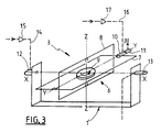
- FIG. 1 schematically represents an orientable element 1, movable in rotation about an axis of inclination X′-X ′ relative to a support 2, itself capable of exhibiting orientation fluctuations, around this axis X′-X ′, relative to an external reference frame, as well as a device 3 for stabilizing the orientable element 1 relative to its support 2.
- a tilt motor 4 is associated with the orientable element 1 for its tilt control relative to the support 2, around the axis X′-X ′.
- An encoder 5 is associated with this motor to raise, if necessary, the instantaneous angular position ⁇ ′ of the orientable element 1 relative to the support 2.
- the stabilization device 3 also called hereinafter "gyroscopic module” is shown isolated in FIG. 3: it mainly comprises a gyroscope 6 comprising a housing 7 here diagrammed by an external frame, an internal frame 8, a router 9, a motor couple 10 and a detector 11.
- the outer casing or frame 7 is linked to a cradle 1 ′ secured to the orientable element 1 by an input shaft embodying an axis XX, called the sensitive axis of the device 3.
- the inner frame 8 is pivotally mounted on the outer frame 7 about an axis Y-Y, perpendicular to the axis X-X and called the exit axis or the precession axis.
- the pivoting movement of the inner frame 8 relative to the outer frame 7 is controlled by the torque motor 10; the detector 11 detects the instantaneous relative position ⁇ between the frames 7 and 8.
- the router 9 is driven in rotation, at high speed, by conventional means not shown around an axis ZZ, perpendicular to the output axis YY and called the router axis, materialized by a shaft engaged in bearings linked to the frame. interior. This axis tends to constitute an inertial reference axis.
- the router axis Z-Z is on average substantially perpendicular to the sensitive axis X-X, which coincides with the axis X′-X ′.
- the axes X-X and X′-X ′ may, as a variant, be parallel, not confused. They may not even be parallel, provided that their angle is less than 90 ° (preferably less than 45 ° or even, better, less than 15 °) and that the inclination axis is not parallel to the axis router (making an angle with it preferably between about 85 and 95 °).
- the outer frame 7, and therefore the gyroscope 6 taken as a whole, is pivotally controlled relative to the orientable element 1, around the axis XX by a motor 12, called the pointing motor. , which is associated with an angular encoder 13 adapted to take up the instantaneous angular position ⁇ of the gyroscope 6 relative to the orientable element 1.
- This pointing motor 12 has a casing which is here integral with the cradle 1 ′ of the orientable element 1 .
- This precession can also be caused directly by the torque motor 10.
- the gyroscopic module 3 also comprises connection lines with external elements.
- the pointing motor 12 receives setpoint signals by a line 14, in practice equipped with an amplifier 15.
- the torque motor 10 receives alignment signals by a line 16, also equipped with an amplifier 17
- the angular encoder 13 transmits the quantity ⁇ by a line 18.
- the encoder 5 likewise transmits the angle ⁇ ′ by a line 19.
- the detector 11 transmits the quantity ⁇ to a processing and filtering circuit 20 which generates a servo signal which, after amplification at 21, is applied to the motor 4. This constitutes a servo loop 22 of the orientable element 1 relative to the support 2.
- the gyroscopic module 3 supplemented by the above lines makes it possible to control the orientable element with various possibilities.
- any angular disturbance around the tilt axis is broken down into a component of rotation parallel to the router axis , which does not induce any reaction from the gyroscopic module, and into a component of rotation around the input shaft, which is subject to precession compensation as indicated above.
- the torque motor 10 is activated accordingly.
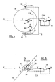
- FIGS. 4 to 9 illustrate an example of a particularly advantageous application of the gyroscopic module 3 of FIG. 1. This is the stabilization along two axes of the input mirror 30 of an on-board telescope (in practice in the nose of 'an airplane), only represented by its entry axis VV. This entry axis is in practice parallel to the longitudinal axis or thrust axis of the aircraft on which it is embarked.
- This mirror 30 is articulated around an axis UU transverse to VV on a fork 31 itself articulated around an axis WW parallel to the axis VV (in practice merged with the latter) on a support structure 32 integral with the 'plane.
- This mirror is on average oriented at 45 ° relative to the axes V-V and W-W so as to be able to reflect along the axis V-V an incident radiation R transverse to the axis of the aircraft. It is elliptical so as to present a disc surface to this radiation. In practice, it has an angular deflection of approximately 10 ° on either side of this average value of 45 ° (under the control of a motor 33) and an angular deflection of at least 90 °, or even more than 180 ° , around the WW axis (under the control of a motor 34).
- each axis U-U and W-W is associated a gyroscopic module of the type described above.
- One of them, noted 3A is associated with the W-W axis
- the other, noted 3B is associated with the U-U axis.
- These gyroscopic modules jointly constitute a device for stabilizing the mirror 30 relative to an external reference.
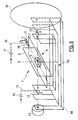
- the gyroscopic module 3A is directly carried by the mirror 30, that is to say that its cradle 1'A (see FIG. 7) is integral with the mirror itself.
- the input axis of his 6A gyroscope is substantially parallel to the W-W axis (at the angular displacement near the mirror relative to the fork (10 ° in practice)).
- the stabilization device 3B is indirectly carried by the mirror while its input axis is parallel to U-U. Its cradle 1′B (see FIG. 8) is in fact connected to the mirror by a mechanical connection such that this cradle rotates twice as fast around an axis parallel to U-U than the mirror itself.
- These gyroscopic modules 3A and 3B are arranged as close as possible to the center of gravity of the mirror.
- Each of these gyroscopic modules is connected to the corresponding motor 33 or 34 along lines forming servo loops 22A or 22B, the details of which appear in FIGS. 7 and 8.
- connection between the supports 2A and 2B and the associated cradles 1′A and 1′B is not, however, as direct as in FIG. 1, but the principle is the same.
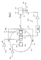
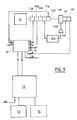
- FIG. 9 is an overall diagram of the control circuit of the stabilization devices, on which only the channel A is represented (corresponding to the elements of FIG. 7), the channel B being only sketched for reasons of visibility but being quite similar to path A.
- This circuit comprises a control, pre-pointing and tracking member 40, in practice consisting of a microprocessor, which transmits to the gyroscopic modules 3A and 3B the orders necessary for the correct orientation of the mirror relative to the axis of the telescope 41 and in return receives the measurement signals.
- a control, pre-pointing and tracking member 40 in practice consisting of a microprocessor, which transmits to the gyroscopic modules 3A and 3B the orders necessary for the correct orientation of the mirror relative to the axis of the telescope 41 and in return receives the measurement signals.
- a tachometer 42 whose speed signal is used at 21A to stabilize the control loop.
- This control member 40 is itself controlled by a computer 43 for navigation and control of the telescope.
- This computer receives various pieces of information, in particular from an inertial navigation center 44 (CIN), or even if necessary from a receiver 45 of NAVSTAR type (satellite positioning system). It also receives external information 46.
- CIN inertial navigation center
- NAVSTAR type satellite positioning system
Landscapes
- Physics & Mathematics (AREA)
- General Physics & Mathematics (AREA)
- Optics & Photonics (AREA)
- Gyroscopes (AREA)
- Telescopes (AREA)
- Control Of Position, Course, Altitude, Or Attitude Of Moving Bodies (AREA)
Claims (11)
- Vorrichtung zur Stabilisierung eines drehbeweglichen schwenkbaren Elements (1, 30) in der Neigung bezüglich eines äußeren Bezugsystems in mindestens einer ersten Neigungsachse (X'-X', U-U, W-W) unter der Steuerung durch einen ersten für diese Achse spezifischen Neigungsmotor (4, 33, 34) bezüglich eines Trägers (2, 31, 32), der seinerseits bezüglich dieses äußeren Bezugssystems beweglich ist, wobei diese Vorrichtung ein erstes gyroskopisches Modul (3, 3B, 3A) besitzt, das eine erste Eingangswelle (X-X) und eine Kreiselachse (Z-Z) besitzt, die zu einer Präzessionsachse (Y-Y) senkrecht ist, die ihrerseits zur Eingangswelle senkrecht ist, die einen Winkel von nicht Null mit dieser Neigungsachse bildet, wobei die Eingangswelle axial und seitlich bezüglich des richtbaren Elements (1, 30) gehalten ist und um sich selbst durch einen ersten Richtmotor (12, 12B, 12A) in Drehung versetzt ist, der Richtsignale erhält und dessen Gehäuse mit einer ersten Wiege (1', 1'B, 1'A) fest verbunden ist, und das erste gyroskopische Modul außerdem einen ersten Präzessionsfühler (11, 11B, 11A) umfaßt, der mit dem Neigungsmotor (4, 33, 34) über einen ersten Regelkreis (20, 20B, 20A) verbunden ist, der zu jedem Zeitpunkt an den Neigungsmotor (4, 33, 34) ein Steuersignal zum Ausgleich einer von diesem Fühler festgestellten momentanen Präzession anlegen kann,
dadurch gekennzeichnet, daß das erste gyroskopische Modul für die Neigungsachse spezifisch ist und mindestens indirekt von dem schwenkbaren Element getragen ist, daß die Wiege dieses spezifischen Moduls ihrerseits bezüglich des Trägers (2, 31, 32) parallel zur Eingangsachse gemäß einer Transmissionsverbindung (1'-1, 35-36, 1'A-30) in Drehung versetzt wird, die ein konstantes Verhältnis K zwischen den Drehungen des schwenkbaren Elements (1, 30) und der Wiege bezüglich dieses Trägers festlegt, daß der Richtmotor dieses spezifischen Moduls und der für die Neigungsachse spezifische Neigungsmotor zwei verschiedene Motoren sind und daß die erste Eingangswelle mit der Neigungsachse einen Winkel von weniger als 90° bildet. - Stabilisierungsvorrichtung nach Anspruch 1, dadurch gekennzeichnet, daß das erste gyroskopische Modul (3, 3A, 3B) außerdem in der Präzessionsachse mit einem Drehmomentmotor (10, 10A, 10B) versehen ist, der Ausrichtungssignale erhält.
- Stabilisierungsvorrichtung nach Anspruch 1 oder Anspruch 2, dadurch gekennzeichnet, daß die Eingangswelle (X-X) zur Neigungsachse (X'-X', U-U, W-W) annähernd parallel ist, und zwar mit einer Abweichung von weniger als 15°.
- Stabilisierungsvorrichtung nach einem der Ansprüche 1 bis 3, dadurch gekennzeichnet, daß die Kreiselachse (Z-Z) zur Neigungsachse (X'-X', U-U, W-W) im wesentlichen senkrecht ist.
- Stabilisierungsvorrichtung nach einem der Ansprüche 1 bis 4, dadurch gekennzeichnet, daß dem Richtmotor (12, 12A, 12B) ein Winkelkodierer (13, 13A, 13B) zugeordnet ist.
- Stabilisierungsvorrichtung nach einem der Ansprüche 1 bis 5, dadurch gekennzeichnet, daß das Gehäuse des Richtmotors (12, 12A) mit dem schwenkbaren Element (1, 30) fest verbunden ist, wobei das Transmissionsverhältnis K = 1 beträgt.
- Stabilisierungsvorrichtung nach einem der Ansprüche 1 bis 5 für die Stabilisierung eines verschwenkbaren Spiegels, dadurch gekennzeichnet, daß die Transmissionsverbindung der Wiege (1'B) des ersten gyroskopischen Moduls (3B) mit dem Spiegel (30) aus einem Paar Zahnräder (35, 36) besteht, die miteinander kämmen, gleiche Zahnzahlen besitzen und von dem Träger bzw. der Eingangswiege getragen sind, wobei das sich das ergebende Transmissionsverhältnis K = 1/2 beträgt.
- Stabilisierungsvorrichtung nach einem der Ansprüche 1 bis 5, dadurch gekennzeichnet, daß das verschwenkbare Element bezüglich des Trägers unter der Steuerung durch einen zweiten Neigungsmotor (34, 33) in einer zweiten, zur ersten Neigungsachse rechtwinkligen Neigungsachse (W-W, U-U) drehbeweglich ist, wobei dieser zweiten Neigungsachse ein zweites gyroskopisches Modul (3A, 3B) zugeordnet ist, das von dem verschwenkbaren Element (30) getragen ist, so daß seine Eingangswelle zur ersten Eingangswelle rechtwinklig ist und mit einem zweiten Richtmotor (12A, 12B) ausgerüstet ist, dessen Gehäuse mit einer zweiten Wiege (1'A, 1'B) fest verbunden ist, die bezüglich des Trägers parallel zur zweiten Neigungsachse gemäß einer zweiten Transmissionsverbindung (1'A-30, 1'B-35-36-30) in Drehung versetzt ist, die ein zweites vom ersten konstanten Verhältnis verschiedenes konstantes Verhältnis K bestimmt, wobei dieses zweite Modul einen zweiten Präzessionsfühler (11A, 11B) besitzt, der an den zweiten Neigungsmotor (34, 33) über einen zweiten Regelkreis (20A, 20B) angeschlossen ist.
- Stabilisierungsvorrichtung nach Anspruch 8, dadurch gekennzeichnet, daß, wenn das verschwenkbare Element ein Reflektor (30) ist, der einer auf dem Träger (32) befindlichen Bordeinrichtung zugeordnet ist und eine bezüglich diesem feststehende Achse (V-V) besitzt, dieser Reflektor unter der Steuerung durch einen zweiten Neigungsmotor (33) um eine die zweite Neigungsachse bildende Querachse (U-U) auf einer Gabel (31) drehbar montiert ist, die auf dem Träger um eine zur Achse der Ausrüstung parallele und die erste Neigungsachse bildende Achse (W-W) unter der Steuerung durch den ersten Neigungsmotor (34) drehbar montiert ist, wobei die erste Wiege (1'A) mit dem Reflektor fest verbunden ist, was ein Transmissionsverhältnis K von gleich 1 festlegt, während die zweite Wiege (1'B) mit einem Zahnrad (36) fest verbunden ist, das mit einem zweiten Zahnrad (35) kämmt, das die gleiche Zahnzahl hat und mit der Gabel fest verbunden ist, was ein Transmissionsverhältnis K von gleich 1/2 festlegt.
- Stabilisierungsvorrichtung nach Anspruch 9, dadurch gekennzeichnet, daß die Eingangswelle des ersten gyroskopischen Moduls annähernd parallel zur ersten Neigungsachse (W-W) ist, während die Eingangswelle des zweiten gyroskopischen Moduls zur zweiten Neigungsachse (U-U) parallel ist.
- Bordteleskopspiegel, der mit einer Stabilisierungsvorrichtung nach einem der Ansprüche 8 bis 10 ausgerüstet ist.
Applications Claiming Priority (2)
| Application Number | Priority Date | Filing Date | Title |
|---|---|---|---|
| FR8717642A FR2624989B1 (fr) | 1987-12-17 | 1987-12-17 | Dispositif inertiel de stabilisation en inclinaison d'un element orientable et miroir de telescope embarque muni d'un tel dispositif |
| FR8717642 | 1987-12-17 |
Publications (2)
| Publication Number | Publication Date |
|---|---|
| EP0321342A1 EP0321342A1 (de) | 1989-06-21 |
| EP0321342B1 true EP0321342B1 (de) | 1994-03-02 |
Family
ID=9357985
Family Applications (1)
| Application Number | Title | Priority Date | Filing Date |
|---|---|---|---|
| EP88403186A Expired - Lifetime EP0321342B1 (de) | 1987-12-17 | 1988-12-14 | Stabilisierendes Trägheitssystem für den Neigungswinkel von orientierbaren Bauteilen und mit diesem System verbundener Teleskopspiegel |
Country Status (6)
| Country | Link |
|---|---|
| US (1) | US4973144A (de) |
| EP (1) | EP0321342B1 (de) |
| JP (1) | JPH01194009A (de) |
| CA (1) | CA1330118C (de) |
| DE (1) | DE3888132T2 (de) |
| FR (1) | FR2624989B1 (de) |
Families Citing this family (7)
| Publication number | Priority date | Publication date | Assignee | Title |
|---|---|---|---|---|
| SE467378B (sv) * | 1989-08-23 | 1992-07-06 | Rolf Eric Ragnar Stroemberg | Troeghetsstabiliseringssystem foer ett instrument |
| US5256942A (en) * | 1992-05-07 | 1993-10-26 | Wood Ross C | Stabilization system for a freely rotatable platform |
| DE4238512C1 (de) * | 1992-11-14 | 1994-01-20 | Deutsche Aerospace | Inertialstabilisierungssystem |
| FR2738925B1 (fr) * | 1995-09-19 | 1997-11-21 | Sagem | Dispositif de visee optique stabilisee |
| SE9603716L (sv) * | 1996-10-11 | 1998-04-06 | Polytech Ab | Anordning för stabilisering av fjärrstyrd sensor, såsom kamera |
| IT1394175B1 (it) * | 2009-05-20 | 2012-06-01 | Insis Spa | Piattaforma optronica di visione a doppio albero coassiale di elevazione per la stabilizzazione della linea di mira (los) |
| FR2974196B1 (fr) | 2011-04-12 | 2014-03-07 | Ixmotion | Systeme de stabilisation d'un positionneur a axes motorises d'un equipement |
Family Cites Families (14)
| Publication number | Priority date | Publication date | Assignee | Title |
|---|---|---|---|---|
| FR475569A (de) * | ||||
| US3378326A (en) * | 1963-09-12 | 1968-04-16 | Bell & Howell Co | Gyroscopically controlled accidental motion compensator for optical instruments |
| FR1439999A (fr) * | 1965-04-08 | 1966-05-27 | Dispositif assurant la stabilisation et le pilotage d'une ligne de visée, au moyen de deux miroirs ou de deux prismes associés à un gyroscope libre, ou à un systèmeéquivalent | |
| DE1548371A1 (de) * | 1966-01-07 | 1971-06-09 | Bundesrep Deutschland | Rundblickfernrohr mit Bildstabilisierung fuer Fahrzeuge |
| US3493283A (en) * | 1967-06-05 | 1970-02-03 | Trw Inc | Apparatus for stabilizing optical instruments |
| FR1549505A (de) * | 1967-10-31 | 1968-12-13 | ||
| US3499332A (en) * | 1968-09-25 | 1970-03-10 | Us Navy | Control system for an inertial platform |
| US3951510A (en) * | 1975-02-25 | 1976-04-20 | Westinghouse Electric Corporation | Inertially stabilized heliostat assembly |
| GB1520845A (en) * | 1976-05-07 | 1978-08-09 | Marconi Co Ltd | Arrangements including mirrors |
| US4155621A (en) * | 1977-12-29 | 1979-05-22 | Mead John A | Image stabilizer for viewing devices |
| SU783587A1 (ru) * | 1979-01-08 | 1980-11-30 | Военный Инженерный Краснознаменный Институт Им. А.Ф.Можайского | Устройство дл измерени скорости уходов гидростабилизатора |
| DE3332416A1 (de) * | 1983-09-08 | 1985-03-21 | Messerschmitt-Bölkow-Blohm GmbH, 8000 München | Richtspiegel mit stabilisierungseinrichtung |
| FR2552893B1 (fr) * | 1983-10-04 | 1986-07-18 | France Etat | Perfectionnements aux appareils d'observation |
| FR2560677B1 (fr) * | 1984-03-02 | 1986-10-24 | Sfim | Structure gyrostabilisee, notamment structure support du miroir mobile d'un viseur periscopique panoramique |
-
1987
- 1987-12-17 FR FR8717642A patent/FR2624989B1/fr not_active Expired - Fee Related
-
1988
- 1988-12-09 CA CA000585544A patent/CA1330118C/en not_active Expired - Fee Related
- 1988-12-14 EP EP88403186A patent/EP0321342B1/de not_active Expired - Lifetime
- 1988-12-14 DE DE3888132T patent/DE3888132T2/de not_active Expired - Fee Related
- 1988-12-16 JP JP63318355A patent/JPH01194009A/ja active Pending
- 1988-12-19 US US07/286,751 patent/US4973144A/en not_active Expired - Fee Related
Also Published As
| Publication number | Publication date |
|---|---|
| FR2624989A1 (fr) | 1989-06-23 |
| DE3888132T2 (de) | 1994-06-01 |
| CA1330118C (en) | 1994-06-07 |
| JPH01194009A (ja) | 1989-08-04 |
| FR2624989B1 (fr) | 1991-08-09 |
| US4973144A (en) | 1990-11-27 |
| EP0321342A1 (de) | 1989-06-21 |
| DE3888132D1 (de) | 1994-04-07 |
Similar Documents
| Publication | Publication Date | Title |
|---|---|---|
| EP0435708B1 (de) | Verfahren zur Steuerung der Neigung eines Satelliten bezüglich der Roll- und der Gierachse | |
| EP0142397B1 (de) | Stabilisierungs- und Richtvorrichtung für Antennen, insbesondere auf Schiffen | |
| EP0031781B1 (de) | Vorrichtungen mit stabilisierter Visierlinie für Fahrzeuge | |
| EP0493227B1 (de) | System zur Lagestabilisierung eines dreiachsenstabilisierten Satelliten auf einer Umlaufbahn mit kleiner Bahnneigung | |
| EP1002716B1 (de) | Methode und Vorrichtung zur Lageregelung eines Satelliten | |
| EP0209429B1 (de) | Vorrichtung und Verfahren zum Einbringen eines Satelliten auf einer geostationären Bahn mit Stabilisierung in den drei Raumachsen | |
| EP0484202A1 (de) | Anordnung für die Ausrichtung des Inertialsystems eines getragenen Fahrzeugs auf das eines Trägerfahrzeuges | |
| FR2734376A1 (fr) | Plate-forme asservie et stabilisee perfectionnee | |
| EP0561660B1 (de) | Verfahren und Vorrichtung zum Bestimmen der relativen Lage und Trajektorie von zwei Raumfahrzeugen | |
| EP0321342B1 (de) | Stabilisierendes Trägheitssystem für den Neigungswinkel von orientierbaren Bauteilen und mit diesem System verbundener Teleskopspiegel | |
| EP0778958B1 (de) | Vorrichtung zum ausrichten eines beobachtungsinstrumentes | |
| FR2746494A1 (fr) | Tete chercheuse pour des missiles ou des projectiles | |
| EP0068932B1 (de) | Zielköpfe bei periskopischen Einrichtungen, insbesondere für Unterseeboote | |
| FR2513373A1 (fr) | Perfectionnements apportes aux installations gyroscopiques de navigation assurant des fonctions de pilotage ou de stabilisation | |
| FR2981149A1 (fr) | Aeronef comprenant un senseur optique diurne et nocturne, et procede de mesure d'attitude associe | |
| EP0985900A1 (de) | Verfahren und Vorrichtung zum Lenken eines Flugkörpers, insbesondere einer Kampfrakete, auf ein Ziel | |
| EP1635485B1 (de) | Optisches Übertragungsverfahren zwischen einem Terminal an Bord eines Raumfahrzeuges, und Raumfahrzeug für das Verfahren | |
| EP0838019B1 (de) | Dreiachsiges inertialsystem mit verschiedenen gyrometertypen | |
| EP0333578B1 (de) | Kreisel mit grosser Dynamik | |
| EP0794404B1 (de) | Verfahren und Vorrichtung zum Leiten eines Flugkörpers zu einem Ziel | |
| FR2728339A1 (fr) | Procede et dispositif pour estimer des biais gyrometriques | |
| FR2689969A1 (fr) | Tête optique de visée, à haute stabilité. | |
| FR2756375A1 (fr) | Procede et dispositif de mesure d'inclinaison d'un axe lie a un porteur | |
| FR2759974A1 (fr) | Procede et systeme integre d'actionneur inertiel et de senseur de vitesses angulaires d'un satellite | |
| FR2550858A1 (fr) | Capteur de position optique pour un satellite |
Legal Events
| Date | Code | Title | Description |
|---|---|---|---|
| PUAI | Public reference made under article 153(3) epc to a published international application that has entered the european phase |
Free format text: ORIGINAL CODE: 0009012 |
|
| AK | Designated contracting states |
Kind code of ref document: A1 Designated state(s): DE ES GB IT NL SE |
|
| 17P | Request for examination filed |
Effective date: 19891127 |
|
| 17Q | First examination report despatched |
Effective date: 19911105 |
|
| GRAA | (expected) grant |
Free format text: ORIGINAL CODE: 0009210 |
|
| AK | Designated contracting states |
Kind code of ref document: B1 Designated state(s): DE ES GB IT NL SE |
|
| PG25 | Lapsed in a contracting state [announced via postgrant information from national office to epo] |
Ref country code: IT Free format text: LAPSE BECAUSE OF FAILURE TO SUBMIT A TRANSLATION OF THE DESCRIPTION OR TO PAY THE FEE WITHIN THE PRE;WARNING: LAPSES OF ITALIAN PATENTS WITH EFFECTIVE DATE BEFORE 2007 MAY HAVE OCCURRED AT ANY TIME BEFORE 2007. THE CORRECT EFFECTIVE DATE MAY BE DIFFERENT FROM THE ONE RECORDED.SCRIBED TIME-LIMIT Effective date: 19940302 Ref country code: ES Free format text: THE PATENT HAS BEEN ANNULLED BY A DECISION OF A NATIONAL AUTHORITY Effective date: 19940302 Ref country code: NL Effective date: 19940302 Ref country code: SE Free format text: THE PATENT HAS BEEN ANNULLED BY A DECISION OF A NATIONAL AUTHORITY Effective date: 19940302 |
|
| REF | Corresponds to: |
Ref document number: 3888132 Country of ref document: DE Date of ref document: 19940407 |
|
| GBT | Gb: translation of ep patent filed (gb section 77(6)(a)/1977) |
Effective date: 19940408 |
|
| NLV1 | Nl: lapsed or annulled due to failure to fulfill the requirements of art. 29p and 29m of the patents act | ||
| PGFP | Annual fee paid to national office [announced via postgrant information from national office to epo] |
Ref country code: GB Payment date: 19941201 Year of fee payment: 7 |
|
| PGFP | Annual fee paid to national office [announced via postgrant information from national office to epo] |
Ref country code: DE Payment date: 19941224 Year of fee payment: 7 |
|
| PLBE | No opposition filed within time limit |
Free format text: ORIGINAL CODE: 0009261 |
|
| STAA | Information on the status of an ep patent application or granted ep patent |
Free format text: STATUS: NO OPPOSITION FILED WITHIN TIME LIMIT |
|
| 26N | No opposition filed | ||
| PG25 | Lapsed in a contracting state [announced via postgrant information from national office to epo] |
Ref country code: GB Effective date: 19951214 |
|
| GBPC | Gb: european patent ceased through non-payment of renewal fee |
Effective date: 19951214 |
|
| PG25 | Lapsed in a contracting state [announced via postgrant information from national office to epo] |
Ref country code: DE Effective date: 19960903 |