EP0561660B1 - Verfahren und Vorrichtung zum Bestimmen der relativen Lage und Trajektorie von zwei Raumfahrzeugen - Google Patents
Verfahren und Vorrichtung zum Bestimmen der relativen Lage und Trajektorie von zwei Raumfahrzeugen Download PDFInfo
- Publication number
- EP0561660B1 EP0561660B1 EP93400501A EP93400501A EP0561660B1 EP 0561660 B1 EP0561660 B1 EP 0561660B1 EP 93400501 A EP93400501 A EP 93400501A EP 93400501 A EP93400501 A EP 93400501A EP 0561660 B1 EP0561660 B1 EP 0561660B1
- Authority
- EP
- European Patent Office
- Prior art keywords
- space vehicle
- approached
- approaching
- tied
- reference point
- Prior art date
- Legal status (The legal status is an assumption and is not a legal conclusion. Google has not performed a legal analysis and makes no representation as to the accuracy of the status listed.)
- Expired - Lifetime
Links
- 238000000034 method Methods 0.000 title claims description 17
- 238000005259 measurement Methods 0.000 claims description 19
- 239000013598 vector Substances 0.000 claims description 8
- 230000003287 optical effect Effects 0.000 claims description 6
- 238000012937 correction Methods 0.000 claims description 3
- 238000012550 audit Methods 0.000 description 34
- 238000006073 displacement reaction Methods 0.000 description 4
- 230000005484 gravity Effects 0.000 description 3
- 238000010586 diagram Methods 0.000 description 2
- 230000002123 temporal effect Effects 0.000 description 2
- 238000013459 approach Methods 0.000 description 1
- 238000010191 image analysis Methods 0.000 description 1
- 238000012545 processing Methods 0.000 description 1
- 230000010349 pulsation Effects 0.000 description 1
- 230000002747 voluntary effect Effects 0.000 description 1
Images

Classifications
-
- G—PHYSICS
- G01—MEASURING; TESTING
- G01C—MEASURING DISTANCES, LEVELS OR BEARINGS; SURVEYING; NAVIGATION; GYROSCOPIC INSTRUMENTS; PHOTOGRAMMETRY OR VIDEOGRAMMETRY
- G01C3/00—Measuring distances in line of sight; Optical rangefinders
- G01C3/22—Measuring distances in line of sight; Optical rangefinders using a parallactic triangle with variable angles and a base of fixed length at, near, or formed by the object
-
- B—PERFORMING OPERATIONS; TRANSPORTING
- B64—AIRCRAFT; AVIATION; COSMONAUTICS
- B64G—COSMONAUTICS; VEHICLES OR EQUIPMENT THEREFOR
- B64G1/00—Cosmonautic vehicles
- B64G1/22—Parts of, or equipment specially adapted for fitting in or to, cosmonautic vehicles
- B64G1/64—Systems for coupling or separating cosmonautic vehicles or parts thereof, e.g. docking arrangements
- B64G1/646—Docking or rendezvous systems
- B64G1/6462—Docking or rendezvous systems characterised by the means for engaging other vehicles
Definitions
- the present invention relates to a method and a device for determining the relative position and the natural relative trajectory of an approaching spacecraft relative to an approached spacecraft.
- natural relative trajectory is meant below that, during the determination of position and trajectory in accordance with the invention, neither the approached spacecraft nor the approaching spacecraft are subjected to voluntary maneuvers, said vehicles then freely describing their respective orbits.
- the present invention relates both to the case where the approaching spacecraft pursues the approached spacecraft, as well as the case where the approaching spacecraft is in front of the approached spacecraft and is braked to be joined by the latter.
- GPS positioning satellites Global Positioning System
- GPS method requires special equipment on board each spacecraft.
- document DE-A-40 19 214 describes a method making it possible to determine the distance between an object and a measuring device provided with a camera which moves relative to said object, on the basis of the variation of the image from two points on the object, assumed to be the same distance from the camera.
- several successive measurements of the image are carried out in order to be able to extrapolate, at any time t , the size of this image and its temporal variation.
- the distance is then obtained from the size of the image, its temporal variation, as well as the relative speed of the device relative to the object in the direction of the optical axis of the camera.
- This prior document therefore only makes it possible to determine the distance between the object and the measurement device, and not the relative position or the relative trajectory.
- this document assumes that the relative speed used is known, which of course limits its possibilities of application.
- the document JP-A-1 305 312 describes a method making it possible to determine, on the one hand, the distance between a hunter and a target, and, on the other hand, an azimuth, from the image of the target taken by a camera mounted on the hunter and using an image processing circuit.
- the distance is determined at from the measured size of the target image and the actual known size of this target.
- this method only makes it possible to determine the distance and an azimuth, and not the position defined in a system of reference axes. Furthermore, it cannot concern the determination of a relative trajectory.
- the object of the present invention is to remedy the drawbacks of the prior art mentioned above. It relates to a simple, reliable, robust, precise system, independent of ground infrastructures and easily embarkable on board a space vehicle, since it has a low mass and consumes little electrical energy.
- the distance between said spacecraft is taken into account, while the determination of the apparent position of the approached spacecraft relative to the spacecraft approaching, in the vertical and horizontal planes, makes it possible to precisely locate said approached spacecraft.
- the observation of the approaching spacecraft can be made on sight.
- the observation of said approached spacecraft be done by means of a recording device. view delivering an image on the scale of that which would have in the case of a direct observation which would make it possible, for example by means of appropriate graduated scales, superimposed on the image, the measurements of site and azimuth required.
- the present invention also relates to a device for determining the relative position and the natural relative trajectory of an approaching spacecraft relative to an approached spacecraft, said approaching and approached spacecraft being located on portions of their respective orbits where their velocity vectors relative to the geocentric reference frame are at least approximately parallel, said approached space vehicle being stabilized three axes in its orbit and said device comprising observation means mounted on board said approaching vehicle, measurement means for determining the apparent size of said approached spacecraft and calculating means for calculating the distance between said approaching and approaching spacecraft from said apparent size and the actual size of said approached spacecraft.
- said measuring means can take many forms, in an advantageous embodiment, they comprise a television device, associated with said shooting device and provided with a screen, each point of which can be identified by the position d 'a movable reticle, movable under the action of a control member.
- Figure 1 schematically illustrates two spacecraft in the approach phase.
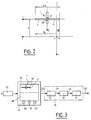
- Figure 2 is a diagram illustrating the principle of the present invention.
- Figure 3 shows the block diagram of a device according to the present invention.
- FIG. 1 two space vehicles 1 and 2 have been represented in the preparatory phase for an appointment.
- Space vehicle 1 for example a manned space station, describes an orbit 3.
- Such an orbit 3 can be circular around the Earth (not shown) and space vehicle 1 can describe orbit 3 in a way uniform, so that the spacecraft 1 is then in uniform rotation around the Earth.
- a local orbital reference frame OX, OY, OZ is linked, accompanying said spacecraft 1 in its rotational movement around the Earth.
- the origin O of said local orbital reference frame may be the center of gravity of the spacecraft 1, while the vertical axis OZ of said reference frame is constantly directed towards the center of the Earth, during the rotational movement of said spacecraft 1 in its orbit 3.
- the axis OX of said local orbital reference frame is oriented along the speed vector V1 ⁇ (with respect to the Earth) of the space vehicle 1 moving in its orbit 3.
- the axis OX is therefore tangent to said orbit 3 and included in the plane of the latter.
- the spacecraft 1 is stabilized three axes on its orbit 3. It comprises solar panels 4, the known wingspan L of which is constantly parallel to the axis OY, orthogonal to the axes OX and OZ.
- the plane OX, OY defines the horizontal plane of the spacecraft 1.
- the spacecraft 2 for example a manned space shuttle, describes an orbit 5.
- a local orbital reference frame ox, oy, oz is linked, accompanying said spacecraft 2 in its movement along its orbit 5.
- L the origin o of this last local orbital frame of reference may be the center of gravity of the spacecraft 2, while the vertical axis oz is constantly directed towards the center of the Earth, during the movement of said spacecraft 2 in its orbit 5.
- L axis ox is oriented according to the speed vector V2 ⁇ (with respect to the Earth) of the space vehicle 2 on its orbit 5.
- the axis ox is therefore tangent to orbit 5 and included in the plane of the latter.
- the oy axis is orthogonal to the ox and oz axes and the ox, oy plane is horizontal.
- FIG. 1 illustrates the case of an appointment in which the approaching space vehicle (vehicle 2) pursues the approached space vehicle (vehicle 1). It goes without saying, however, that the present invention is also applicable in the case where the approaching vehicle is overtaken by the approached space vehicle.
- the spacecraft 1 appears with an apparent wingspan LA for its solar panels 4 (with real wingspan L), in a position offset relative to the frame of reference ox, oy, oz.
- the apparent span LA is directly representative of the distance D separating the two space vehicles 1 and 2.
- Each of these three angles could, for example, be measured by the rotation of an orientable telescopic sight (not shown) moved between a reference position, for which its optical axis coincides with the ox axis, and a position of sight, for which said optical axis is directed, respectively, towards the OY axis and the ends of said solar panels 4.
- FIG. 3 describes other measurement means, bearing the reference 11.
- the value of the coordinates X, Y and Z is calculated at two instants t1 and t2 by the above method.
- Two groups of values X1, Y1, Z1 and X2, Y2, Z2 are therefore obtained, from which it is possible to determine, at time t1, the components Xp1, Yp1, Zp1 of the relative speed of the spacecraft 2 in the OX, OY, OZ repository.
- the time difference between the instants t1 and t2 is chosen so that the coordinates X1, Y1, Z1 and X2, Y2, Z2 correspond to a sufficient position variation for the spacecraft 2, so that the measurement is significant.
- X (t) X1 - 2 / ⁇ ⁇ Zp1 cos [ ⁇ (t-t1)] + 3 ⁇ Z1 - 2Xp1) cos [ ⁇ (t-
- FIG 3 there is shown an embodiment of the device according to the present invention.
- This embodiment mounted on board the spacecraft 2, comprises a camera 10 observing the spacecraft 1, a television device 11 and three calculation means 12, 13 and 14, possibly grouped in a single computer 15.
- the television device 11 comprises a screen 16 and it is of the type in which reticles 17, 18 and 19, respectively movable under the action of control members 20, 21, 22 (for example rotary knobs), can be moved on said screen 16 by indicating their position thereon.
- control members 20, 21, 22 for example rotary knobs
- the camera 10 forms on the screen 16 an apparent image of the spacecraft 1 whose size is on the scale of the apparent size which would result from a direct observation of said spacecraft 1, from the spacecraft 2.
- the control member 20 is actuated so that the reticle 17 passes through the median horizontal plane of said image, so that the television device 11 knows the site value s1.
- the control members 21 and 22 are also actuated, so that the reticles 18 and 19 are brought to the left and right end of the span of said image of the vehicle 1.
- said reticles 17, 18 and 19 are moved, so that the television device 11 now knows the measurements s2, ag2 and ad2.
- the device described with reference to FIG. 3 is only one possible embodiment of the device according to the present invention.
- the television device 11 could be replaced by an automatic image analysis device for the complete automation of the device of the invention, or else the whole of the camera 10 and the device television 11 could be replaced by a graduated collimator system or a head-up viewfinder, for the human capture of measurements s1, s2, ag1, ag2, ad1 and ad2, which would then be entered into the computer 15.
Landscapes
- Engineering & Computer Science (AREA)
- Remote Sensing (AREA)
- Physics & Mathematics (AREA)
- Aviation & Aerospace Engineering (AREA)
- Electromagnetism (AREA)
- General Physics & Mathematics (AREA)
- Radar, Positioning & Navigation (AREA)
- Navigation (AREA)
- Control Of Position, Course, Altitude, Or Attitude Of Moving Bodies (AREA)
- Position Fixing By Use Of Radio Waves (AREA)
Claims (10)
- Verfahren zur Bestimmung der relativen Position und der natürlichen relativen Flugbahn eines sich annähernden Raumfahrzeugs (2) gegenüber einem angenäherten Raumfahrzeug (1), wobei sich das annähernde und das angenäherte Raumfahrzeug auf Abschnitten ihrer entsprechenden Umlaufbahnen (5,3) befinden, auf denen ihre Geschwindigkeitsvektoren (


dadurch gekennzeichnet:- daß die Beobachtung des angenäherten Raumfahrzeugs (1) in einer Ebene (oy,oz) des sich annähernden Raumfahrzeugs erfolgt, die senkrecht zur Achse des Beobachtungsmittels und durch einen Bezugspunkt (o) des sich annähernden Raumfahrzeugs verläuft;- daß zu jedem von zwei aufeinanderfolgenden Augenblicken t1 und t2:. in dieser Ebene bezogen auf den Bezugspunkt (o) des sich annähernden Raumfahrzeugs die scheinbare Position des angenäherten Raumfahrzeugs gemessen wird;. in dieser Ebene die scheinbare Größe des angenäherten Raumfahrzeugs gemessen wird und. mit Hilfe der Messungen von scheinbarer Position und Größe sowie der tatsächlichen Größe des angenäherten Raumfahrzeugs die Position des Bezugspunkts (o) des sich annähernden Raumfahrzeugs in einem System von Bezugsachsen (OX,OY,OZ) des angenäherten Raumfahrzeugs gemessen wird;- daß aus den beiden Positionen des Bezugspunkts (o), die für die Augenblicke t1 und t2 errechnet wurden, sowie aus den bekannten Bewegungsdaten des angenäherten Raumfahrzeugs auf seiner Umlaufbahn im Bezugsachsensystem (0X,0Y,0Z) des angenäherten Raumfahrzeugs für den Augenblick t1 die Komponenten der relativen Geschwindigkeit des sich annähernden Raumfahrzeugs gegenüber dem angenäherten Raumfahrzeug berechnet werden, und- dadurch, daß aus der Position des für den Augenblick t1 berechneten Bezugspunktes und den Komponenten der relativen Geschwindigkeit, die ebenfalls für den Augenblick t1 berechnet wurden, im Bezugsachsensystem des angenäherten Raumfahrzeugs die Positionskoordinaten des Bezugspunkts des sich annähernden Raumfahrzeugs für einen beliebigen Augenblick t berechnet werden. - Verfahren nach Anspruch 1, angewendet auf den Fall, daß das angenäherte Raumfahrzeug eine bekannte große horizontale Spannweite L hat,
dadurch gekennzeichnet:- daß für jeden Augenblick t1 und t2:. der Wert s1 bzw. s2 des Höhenwinkels von Nullpunkt (0) des Bezugsachsensystems des angenäherten Raumfahrzeugs gegenüber dem Bezugspunkt (o) des sich annähernden Raumfahrzeugs gemessen wird;. die Werte ag1,ad1 bzw. ag2,ad2 der Azimutwinkel des linken und rechten Endes des angenäherten Raumfahrzeugs gegenüber dem Bezugspunkt des sich annähernden Raumfahrzeugs gemessen werden;. aus der Spannweite L und den Höhenwinkel- und Azimutmessungen s1,ag1,ad1 bzw. s2,ag2,ad2 die entsprechenden Positionskoordinaten X1,Y1,Z1 und X2,Y2,Z2 des Bezugspunkts des sich annähernden Raumfahrzeugs im Bezugsachsensystem des angenäherten Raumfahrzeugs berechnet werden;- daß aus den für die Augenblicke t1 und t2 berechneten Positionskoordinaten X1,Y1,Z1 und X2,Y2,Z2 sowie aus den bekannten Bewegungsdaten des angenäherten Raumfahrzeugs auf seiner Umlaufbahn im Bezugsachsensystem des angenäherten Raumfahrzeugs die Komponenten Xp1, Yp1 und Zp1 der relativen Geschwindigkeit des sich annähernden Raumfahrzeugs gegenüber dem angenäherten Raumfahrzeug für den Augenblick t1 berechnet werden, und- daß aus den Positionskoordinaten X1,Y1,Z1 und den Geschwindigkeitskomponenten Xp1, Yp1 und Zp1, die für den Augenblick t1 berechnet wurden, die Positionskoordinaten X(t), Y(t) und Z(t) des Bezugspunkts des sich annähernden Raumfahrzeugs für einen beliebigen Augenblick t berechnet werden. - Verfahren nach Anspruch 2,
dadurch gekennzeichnet, daß die Beobachtung des angenäherten Raumfahrzeugs mit Hilfe einer Aufnahmevorrichtung erfolgt, die eine Abbildung in einer Größe liefert, die gleich dem Maßstab der scheinbaren Größe bei einer direkten Beobachtung ist. - Verfahren nach Anspruch 3, bei dem die optische Achse der Aufnahmevorrichtung gegenüber dem Geschwindigkeitsvektor des sich annähernden Raumfahrzeugs versetzt ist,
dadurch gekennzeichnet, daß vor der Berechnung der Koordinaten X1, Y1, Z1, X2, Y2 und Z2 an den Höhenwinkel- und Azimutwerten s1, s2, ag1, ad1, ag2 und ad2 entsprechende Korrekturwerte angebracht werden. - Verfahren nach Anspruch 2, bei dem das angenäherte Raumfahrzeug gleichförmig eine Kreisbahn mit einer Kreisfrequenz ω beschreibt, dadurch gekennzeichnet, daß die Komponenten der relativen Geschwindigkeit Xp1, Yp1 und Zp1 jeweils lauten:


- Verfahren nach Anspruch 5,
dadurch gekennzeichnet, daß die Positionskoordinaten X(t), Y(t) und Z(t) jeweils lauten :
- Vorrichtung zur Bestimmung der relativen Position und der natürlichen relativen Flugbahn eines sich annähernden Raumfahrzeugs (2) gegenüber einem angenäherten Raumfahrzeug (1), wobei sich das sich annähernde und das angenäherte Raumfahrzeug auf Abschnitten ihrer entsprechenden Umlaufbahnen (5,3) befinden, auf denen ihre Geschwindigkeitsvektoren (


dadurch gekennzeichnet, daß:- die Beobachtungsmittel (10) das angenäherte Raumfahrzeug (1) in einer Ebene (oz, oy) des sich annähernden Raumfahrzeugs beobachten, die senkrecht zur Achse der Beobachtungsmittel durch einen Bezugspunkt (o) des sich annähernden Raumfahrzeugs verläuft;- die Meßmittel (11) in jedem von zwei aufeinanderfolgenden Augenblicken t1 und t2:. in dieser Ebene bezogen auf den Bezugspunkt des sich annähernden Raumfahrzeugs die scheinbare Position eines charakteristischen Punktes des angenäherten Raumfahrzeugs und. in dieser Ebene die scheinbare Größe des angenäherten Raumfahrzeugs messen;und dadurch, daß die Rechenmittel umfassen:- erste Rechenmittel (12), mit denen in jedem Augenblick t1 und t2 mit Hilfe der Messungen von scheinbarer Position und Größe sowie der tatsächlichen Größe des angenäherten Fahrzeugs die Position des Bezugspunkts des sich annähernden Raumfahrzeugs in einem Bezugsachsensystem des angenäherten Raumfahrzeugs berechnet werden;- zweite Rechenmittel (13), mit denen aus den beiden Positionen des Bezugspunktes, die für die Augenblicke t1 und t2 berechnet wurden, sowie aus den bekannten Bewegungsdaten des angenäherten Raumfahrzeugs auf seiner Umlaufbahn im Bezugsachsensystem des angenäherten Raumfahrzeugs für den Augenblick t1 die Komponenten der relativen Geschwindigkeit des sich annähernden Raumfahrzeugs gegenüber dem angenäherten Raumfahrzeug berechnet werden, und- dritte Rechenmittel (14), mit denen aus der für den Augenblick t1 berechneten Position des Bezugspunktes und den ebenfalls für den Augenblick t1 berechneten relativen Geschwindigkeitskomponenten im Bezugsachsensystem des angenäherten Raumfahrzeugs die Positionskoordinaten des Bezugspunkts des sich annähernden Raumfahrzeugs für einen beliebigen Augenblick t berechnet werden. - Vorrichtung nach Anspruch 7 für den Fall, daß das angenäherte Raumfahrzeug eine bekannte große horizontale Spannweite L hat,
dadurch gekennzeichnet,- daß die Meßmittel (11) für jeden Augenblick t1 und t2:. den Wert s1 bzw. s2 des Höhenwinkels von Nullpunkt (0) des Bezugsachsensystems des angenäherten Raumfahrzeugs gegenüber dem Bezugspunkt (o) des sich annähernden Raumfahrzeugs messen, und. die Werte ag1,ad1 bzw. ag2,ad2 der Azimute des linken und rechten Endes des angenäherten Raumfahrzeugs gegenüber dem Bezugspunkt des sich annähernden Raumfahrzeugs messen;- daß die ersten Rechenmittel (12) aus der Spannweite L und den Höhenwinkel- und Azimutmessungen s1,ag1,ad1 bzw. s2,ag2,ad2 die entsprechenden Positionskoordinaten X1,Y1,Z1 und X2,Y2,Z2 des Bezugspunkts des sich annähernden Raumfahrzeugs im Bezugsachsensystem des angenäherten Raumfahrzeugs errechnen;- daß die zweiten Rechenmittel (13) aus den für die Augenblicke t1 und t2 berechneten Positionskoordinaten X1,Y1,Z1 und X2,Y2,Z2 sowie aus den bekannten Bewegungsdaten des angenäherten Raumfahrzeugs auf seiner Umlaufbahn im Bezugsachsensystem des angenäherten Raumfahrzeugs die Komponenten Xp1, Yp1 und Zp1 der relativen Geschwindigkeit des sich annähernden Raumfahrzeugs gegenüber dem angenäherten Raumfahrzeug berechnen, und- daß die dritten Rechenmittel (14) aus den Positionskoordinaten X1,Y1,Z1 und den Geschwindigkeitskomponenten Xp1, Yp1 und Zp1, die für den Augenblick t1 berechnet wurden, die Positionskoordinaten X(t), Y(t) und Z(t) des Bezugspunktes des sich annähernden Raumfahrzeugs für einen beliebigen Augenblick t errechnen. - Vorrichtung nach Anspruch 8,
dadurch gekennzeichnet, daß die Beobachtungsmittel eine Aufnahmevorrichtung (10) haben, die eine Abbildung in einer Größe liefert, die gleich dem Maßstab der scheinbaren Größe bei einer direkten Beobachtung ist. - Vorrichtung nach einem der Ansprüche 8 oder 9,
dadurch gekennzeichnet, daß die Meßmittel (11) eine TV-Vorrichtung mit einem Bildschirm (16) haben, auf dem jeder Punkt durch die Lage eines beweglichen Fadenkreuzes (17,18,19) identifiziert werden kann, das mit Hilfe eines Steuerorgans (20,21,22) verschoben werden kann.
Applications Claiming Priority (2)
| Application Number | Priority Date | Filing Date | Title |
|---|---|---|---|
| FR9203094A FR2688613B1 (fr) | 1992-03-16 | 1992-03-16 | Procede et dispositif pour la determination de la position et de la trajectoire relatives de deux vehicules spatiaux. |
| FR9203094 | 1992-03-16 |
Publications (2)
| Publication Number | Publication Date |
|---|---|
| EP0561660A1 EP0561660A1 (de) | 1993-09-22 |
| EP0561660B1 true EP0561660B1 (de) | 1996-04-17 |
Family
ID=9427706
Family Applications (1)
| Application Number | Title | Priority Date | Filing Date |
|---|---|---|---|
| EP93400501A Expired - Lifetime EP0561660B1 (de) | 1992-03-16 | 1993-02-26 | Verfahren und Vorrichtung zum Bestimmen der relativen Lage und Trajektorie von zwei Raumfahrzeugen |
Country Status (8)
| Country | Link |
|---|---|
| US (1) | US5436841A (de) |
| EP (1) | EP0561660B1 (de) |
| JP (1) | JP3390481B2 (de) |
| CA (1) | CA2091613C (de) |
| DE (1) | DE69302207T2 (de) |
| FR (1) | FR2688613B1 (de) |
| RU (1) | RU2103202C1 (de) |
| UA (1) | UA27739C2 (de) |
Cited By (1)
| Publication number | Priority date | Publication date | Assignee | Title |
|---|---|---|---|---|
| DE10130623C1 (de) * | 2001-06-22 | 2003-02-06 | Jena Optronik Gmbh | Verfahren zur Bestimmung der Zustandsgrößen eines starren Körpers im Raum mittels eines Videometers |
Families Citing this family (17)
| Publication number | Priority date | Publication date | Assignee | Title |
|---|---|---|---|---|
| JPH0728387A (ja) * | 1993-07-14 | 1995-01-31 | Hitachi Ltd | 移動体の運動計画方法及び装置 |
| US6847336B1 (en) * | 1996-10-02 | 2005-01-25 | Jerome H. Lemelson | Selectively controllable heads-up display system |
| JPH10170302A (ja) * | 1996-12-10 | 1998-06-26 | Toshiba Corp | 方向検出装置 |
| DE10011890C2 (de) * | 2000-03-03 | 2003-04-24 | Jena Optronik Gmbh | Verfahren zur Bestimmung der Zustandsgrössen eines sich bewegenden starren Körpers im Raum |
| RU2276836C2 (ru) * | 2004-01-28 | 2006-05-20 | Открытое акционерное общество "Ракетно-космическая корпорация "Энергия" им. С.П. Королева" | Система космической оптической связи между кооперируемым объектом и объектом-корреспондентом |
| AU2004202179B2 (en) * | 2004-05-20 | 2011-04-21 | The Boeing Company | Method and apparatus for covertly determining the rate of relative motion between two objects |
| RU2275650C1 (ru) * | 2004-11-19 | 2006-04-27 | Закрытое акционерное общество "НПО Космического Приборостроения" | Способ определения местоположения космических аппаратов |
| RU2547286C2 (ru) * | 2013-08-20 | 2015-04-10 | Открытое акционерное общество "Ракетно-космическая корпорация "Энергия" имени С.П. Королева" | Система контроля скорости космических аппаратов при сближении |
| CN104229161B (zh) * | 2014-08-22 | 2016-08-24 | 北京控制工程研究所 | 一种基于制导脉冲的交会对接轨迹安全带确定方法 |
| JP6670837B2 (ja) | 2014-08-26 | 2020-03-25 | イフェクティブ・スペース・ソリューションズ・リミテッドEffective Space Solutions Ltd | 衛星のためのドッキングシステムおよびドッキング方法 |
| RU2603301C1 (ru) * | 2015-07-20 | 2016-11-27 | Михаил Викторович Яковлев | Способ синхронизации угловых скоростей движения активного космического аппарата с пассивным космическим аппаратом |
| US10625882B2 (en) | 2017-03-06 | 2020-04-21 | Effective Space Solutions Ltd. | Service satellite for providing in-orbit services using variable thruster control |
| RU2662318C1 (ru) * | 2017-05-29 | 2018-07-25 | Михаил Викторович Яковлев | Способ синхронизации угловых скоростей активного космического аппарата с пассивным космическим аппаратом |
| RU2750077C2 (ru) * | 2017-10-05 | 2021-06-21 | Российская Федерация, от имени которой выступает Государственная корпорация по космической деятельности "РОСКОСМОС" | Способ синхронизации угловой скорости вращения активного космического аппарата с пассивным космическим аппаратом при выполнении операции обслуживания |
| CN113777955B (zh) * | 2021-09-01 | 2024-05-07 | 哈尔滨工业大学 | 双航天器跟踪指向装置和方法 |
| CN114530018B (zh) * | 2022-04-24 | 2022-08-16 | 浙江华眼视觉科技有限公司 | 一种基于取件人轨迹分析的语音提示方法及装置 |
| CN117564887B (zh) * | 2023-12-07 | 2026-01-30 | 武汉永鼎光电子技术有限公司 | Wdm半成品器件返修工艺 |
Family Cites Families (7)
| Publication number | Priority date | Publication date | Assignee | Title |
|---|---|---|---|---|
| US3910533A (en) * | 1973-06-15 | 1975-10-07 | Nasa | Spacecraft docking and alignment system |
| US4591987A (en) * | 1983-07-27 | 1986-05-27 | Kollmorgen Technologies Corp. | Video rangefinder |
| US4834531A (en) * | 1985-10-31 | 1989-05-30 | Energy Optics, Incorporated | Dead reckoning optoelectronic intelligent docking system |
| JPH01305312A (ja) * | 1988-06-03 | 1989-12-08 | Nec Corp | ランデブドッキング用近接センサ |
| US4898349A (en) * | 1988-12-09 | 1990-02-06 | General Electric Company | Spacecraft approach/separation by use of angular measurement |
| JP2736122B2 (ja) * | 1989-07-14 | 1998-04-02 | 株式会社東芝 | 目標物の位置推定装置 |
| DE4019214A1 (de) * | 1990-06-15 | 1991-12-19 | Volker Prof Dr Graefe | Verfahren und vorrichtung zur abstandsmessung zwischen einem messobjekt und einer relativ zum messobjekt bewegten messeinrichtung |
-
1992
- 1992-03-16 FR FR9203094A patent/FR2688613B1/fr not_active Expired - Fee Related
-
1993
- 1993-02-26 EP EP93400501A patent/EP0561660B1/de not_active Expired - Lifetime
- 1993-02-26 DE DE69302207T patent/DE69302207T2/de not_active Expired - Fee Related
- 1993-03-10 US US08/029,416 patent/US5436841A/en not_active Expired - Lifetime
- 1993-03-15 CA CA002091613A patent/CA2091613C/fr not_active Expired - Fee Related
- 1993-03-15 JP JP05384593A patent/JP3390481B2/ja not_active Expired - Fee Related
- 1993-03-15 RU RU93004616A patent/RU2103202C1/ru not_active IP Right Cessation
- 1993-06-11 UA UA93002885A patent/UA27739C2/uk unknown
Cited By (1)
| Publication number | Priority date | Publication date | Assignee | Title |
|---|---|---|---|---|
| DE10130623C1 (de) * | 2001-06-22 | 2003-02-06 | Jena Optronik Gmbh | Verfahren zur Bestimmung der Zustandsgrößen eines starren Körpers im Raum mittels eines Videometers |
Also Published As
| Publication number | Publication date |
|---|---|
| CA2091613A1 (fr) | 1993-09-17 |
| RU2103202C1 (ru) | 1998-01-27 |
| DE69302207D1 (de) | 1996-05-23 |
| UA27739C2 (uk) | 2000-10-16 |
| US5436841A (en) | 1995-07-25 |
| JPH0616196A (ja) | 1994-01-25 |
| FR2688613A1 (fr) | 1993-09-17 |
| DE69302207T2 (de) | 1996-08-14 |
| JP3390481B2 (ja) | 2003-03-24 |
| CA2091613C (fr) | 2003-02-18 |
| FR2688613B1 (fr) | 1997-01-17 |
| EP0561660A1 (de) | 1993-09-22 |
Similar Documents
| Publication | Publication Date | Title |
|---|---|---|
| CA2091613C (fr) | Procede et dispositif pour la determination de la position et de la trajectoire relatives de deux vehicules spatiaux | |
| EP2932182B1 (de) | Verfahren zur genauen geolokalisierung eines bildsensors an bord eines flugzeugs | |
| CA2031178A1 (fr) | Systeme optoelectronique d'aide aux missions aeriennes d'attaque et de navigation | |
| FR2694638A1 (fr) | Procédé et dispositif de compensation de mouvement d'images à ouverture synthétique au moyen d'un système de référence ligne de vol/position. | |
| FR2638544A1 (fr) | Systeme pour determiner la position spatiale d'un objet en mouvement, applique notamment a l'atterrissage des avions | |
| EP1178334B1 (de) | Satellitenkonstellation zur Messung der atmosphärischen Windgeschwindigkeit mittels Doppler Lidar | |
| WO2001049565A1 (en) | Method and apparatus for autonomous solar navigation | |
| EP0778958B1 (de) | Vorrichtung zum ausrichten eines beobachtungsinstrumentes | |
| EP1828802B1 (de) | Einrichtung zur autonomen bestimmung absoluter geographischer koordinaten einer sich in bezug auf immersion ändernden mobilen einrichtung | |
| KR100571120B1 (ko) | 레이저 장치를 이용한 3차원 측위 시스템 | |
| EP0016684B1 (de) | Vorrichtung zur Bestimmung einer Visierlinie | |
| CA3100115C (fr) | Procede d'harmonisation de deux unites de mesure inertielle l'une avec l'autre et systeme de navigation mettant en oeuvre ce procede | |
| EP0321342B1 (de) | Stabilisierendes Trägheitssystem für den Neigungswinkel von orientierbaren Bauteilen und mit diesem System verbundener Teleskopspiegel | |
| EP3620852B1 (de) | Luftbildaufnahmeverfahren einer geografischen zone, 3d-kartografieverfahren einer geografischen zone und luftfahrzeug zur ausführung dieses verfahrens | |
| WO2005088379A1 (fr) | Procede d'occultation stellaire, dispositif et ensemble de mise en oeuvre du procede | |
| EP0013195B1 (de) | Luft-Boden-Entfernungsradar für ein Bordfeuerleitsystem und Verwendung eines solchen Radars bei einem Feuerleitsystem | |
| Afia | Development of GNSS/INS/SLAM Algorithms for Navigation in Constrained Environments | |
| EP0631111B1 (de) | Verfahren und Vorrichtung zum Bestimmen der Position eines Flugkörpers | |
| USH712H (en) | Method of stellar navigation using an optical correlator | |
| FR2611266A1 (fr) | Dispositif et procede de localisation de vues au sol prises d'un satellite | |
| FR3026837A1 (fr) | Dispositif et procede de positionnement d'un capteur stellaire sur la structure d'un satellite | |
| EP3851794B1 (de) | Verfahren zur geolokalisierung eines zielpunkts | |
| FR3040097A3 (fr) | Instrument de topographie d'artillerie embarque base sur une technologie de navigation inertielle, avec un bras motorise | |
| EP1635485A1 (de) | Optisches Übertragungsverfahren zwischen einem Terminal an Bord eines Raumfahrzeuges, und Raumfahrzeug für das Verfahren | |
| JPH07291199A (ja) | 人工衛星の姿勢制御方法 |
Legal Events
| Date | Code | Title | Description |
|---|---|---|---|
| PUAI | Public reference made under article 153(3) epc to a published international application that has entered the european phase |
Free format text: ORIGINAL CODE: 0009012 |
|
| AK | Designated contracting states |
Kind code of ref document: A1 Designated state(s): BE DE ES GB IT SE |
|
| 17P | Request for examination filed |
Effective date: 19931011 |
|
| 17Q | First examination report despatched |
Effective date: 19941125 |
|
| GRAA | (expected) grant |
Free format text: ORIGINAL CODE: 0009210 |
|
| AK | Designated contracting states |
Kind code of ref document: B1 Designated state(s): BE DE ES GB IT SE |
|
| PG25 | Lapsed in a contracting state [announced via postgrant information from national office to epo] |
Ref country code: ES Free format text: THE PATENT HAS BEEN ANNULLED BY A DECISION OF A NATIONAL AUTHORITY Effective date: 19960417 |
|
| REF | Corresponds to: |
Ref document number: 69302207 Country of ref document: DE Date of ref document: 19960523 |
|
| GBT | Gb: translation of ep patent filed (gb section 77(6)(a)/1977) |
Effective date: 19960528 |
|
| ITF | It: translation for a ep patent filed | ||
| PG25 | Lapsed in a contracting state [announced via postgrant information from national office to epo] |
Ref country code: SE Effective date: 19960717 |
|
| PG25 | Lapsed in a contracting state [announced via postgrant information from national office to epo] |
Ref country code: BE Effective date: 19970228 |
|
| PLBE | No opposition filed within time limit |
Free format text: ORIGINAL CODE: 0009261 |
|
| STAA | Information on the status of an ep patent application or granted ep patent |
Free format text: STATUS: NO OPPOSITION FILED WITHIN TIME LIMIT |
|
| 26N | No opposition filed | ||
| BERE | Be: lapsed |
Owner name: AEROSPATIALE SOC. NATIONALE INDUSTRIELLE Effective date: 19970228 |
|
| REG | Reference to a national code |
Ref country code: GB Ref legal event code: IF02 |
|
| PGFP | Annual fee paid to national office [announced via postgrant information from national office to epo] |
Ref country code: DE Payment date: 20070131 Year of fee payment: 15 |
|
| PGFP | Annual fee paid to national office [announced via postgrant information from national office to epo] |
Ref country code: GB Payment date: 20070221 Year of fee payment: 15 |
|
| PGFP | Annual fee paid to national office [announced via postgrant information from national office to epo] |
Ref country code: IT Payment date: 20070607 Year of fee payment: 15 |
|
| GBPC | Gb: european patent ceased through non-payment of renewal fee |
Effective date: 20080226 |
|
| PG25 | Lapsed in a contracting state [announced via postgrant information from national office to epo] |
Ref country code: DE Free format text: LAPSE BECAUSE OF NON-PAYMENT OF DUE FEES Effective date: 20080902 |
|
| PG25 | Lapsed in a contracting state [announced via postgrant information from national office to epo] |
Ref country code: GB Free format text: LAPSE BECAUSE OF NON-PAYMENT OF DUE FEES Effective date: 20080226 |
|
| PG25 | Lapsed in a contracting state [announced via postgrant information from national office to epo] |
Ref country code: IT Free format text: LAPSE BECAUSE OF NON-PAYMENT OF DUE FEES Effective date: 20080226 |