EP0321402B1 - Procédé de commande ou du réglage de l'encrage d'une presse à imprimer - Google Patents
Procédé de commande ou du réglage de l'encrage d'une presse à imprimer Download PDFInfo
- Publication number
- EP0321402B1 EP0321402B1 EP88810844A EP88810844A EP0321402B1 EP 0321402 B1 EP0321402 B1 EP 0321402B1 EP 88810844 A EP88810844 A EP 88810844A EP 88810844 A EP88810844 A EP 88810844A EP 0321402 B1 EP0321402 B1 EP 0321402B1
- Authority
- EP
- European Patent Office
- Prior art keywords
- colour
- location
- color
- correction
- space
- Prior art date
- Legal status (The legal status is an assumption and is not a legal conclusion. Google has not performed a legal analysis and makes no representation as to the accuracy of the status listed.)
- Expired - Lifetime
Links
- 238000000034 method Methods 0.000 title claims description 20
- 230000001105 regulatory effect Effects 0.000 title description 2
- 230000001276 controlling effect Effects 0.000 title 1
- 238000012937 correction Methods 0.000 claims description 52
- 239000013598 vector Substances 0.000 claims description 22
- 229910000679 solder Inorganic materials 0.000 description 15
- 239000000976 ink Substances 0.000 description 12
- 238000012545 processing Methods 0.000 description 10
- 239000003086 colorant Substances 0.000 description 9
- 238000011217 control strategy Methods 0.000 description 9
- 238000006243 chemical reaction Methods 0.000 description 8
- 239000011159 matrix material Substances 0.000 description 8
- 230000035945 sensitivity Effects 0.000 description 7
- 239000007787 solid Substances 0.000 description 7
- 230000035515 penetration Effects 0.000 description 4
- 238000000926 separation method Methods 0.000 description 4
- 230000006835 compression Effects 0.000 description 3
- 238000007906 compression Methods 0.000 description 3
- 230000000694 effects Effects 0.000 description 3
- 238000010276 construction Methods 0.000 description 2
- 238000005259 measurement Methods 0.000 description 2
- 238000001514 detection method Methods 0.000 description 1
- 238000010586 diagram Methods 0.000 description 1
- 238000001303 quality assessment method Methods 0.000 description 1
- 230000035807 sensation Effects 0.000 description 1
- 238000012360 testing method Methods 0.000 description 1
Images

Classifications
-
- B—PERFORMING OPERATIONS; TRANSPORTING
- B41—PRINTING; LINING MACHINES; TYPEWRITERS; STAMPS
- B41F—PRINTING MACHINES OR PRESSES
- B41F33/00—Indicating, counting, warning, control or safety devices
- B41F33/0036—Devices for scanning or checking the printed matter for quality control
- B41F33/0045—Devices for scanning or checking the printed matter for quality control for automatically regulating the ink supply
-
- B—PERFORMING OPERATIONS; TRANSPORTING
- B41—PRINTING; LINING MACHINES; TYPEWRITERS; STAMPS
- B41P—INDEXING SCHEME RELATING TO PRINTING, LINING MACHINES, TYPEWRITERS, AND TO STAMPS
- B41P2233/00—Arrangements for the operation of printing presses
- B41P2233/50—Marks on printed material
- B41P2233/51—Marks on printed material for colour quality control
Definitions
- the invention relates to a method for color control or color regulation of a printing press according to the preamble of claim 1.
- EP-A 228347 discloses a method of the type mentioned in the introduction in which a large number are used to optimally match the color impression be evaluated by reference fields in order to compare the color location of the respectively scanned reference field with a color location specified for this reference field and to determine a layer thickness change control vector from the color distance between the actual color location and the target color location, which adjusts the ink guide elements of the printing machine in such a way that a the smallest possible color deviation is achieved.
- EP-A 124908 describes a device and a method for determining the required raster area coverage of color separations, which can be displayed in percent, in order to reproduce the color of a given template pattern to be reproduced as accurately as possible.
- the known device has a measuring head which contains, for example, filters for the colors red, green and blue and allows color information, in particular color densities, of the respective scanned documents to be measured using these filters.
- the measuring head is connected to a data processing device, which has a keyboard used in the scanning of predetermined reference patterns for entering raster area coverage in percent.
- the data processing device furthermore has a display device for displaying raster area coverages calculated on the basis of the scanning of a template pattern.
- a conversion table for converting color information into raster area coverage levels which is stored in a memory of the data processing device.
- First a color sample card is printed.
- the colors cyan, magenta, yellow and black are used to print the color sample card, grid area covers between 0% and 100% being used in increments of 10% for all colors. This results in 14,641 combinations for the grid area coverings and the associated color information, for example recorded as color densities.
- the combination of the screen area covers used is entered via the keyboard and assigned to the color densities detected by the measuring head.
- the device When the conversion table has been created, the device allows a template sample to be reprinted to be scanned using the measuring head and, by comparing the color densities recorded using the various filters with the color densities stored in the conversion table, the row in the conversion table whose color density values match those with be determined measured color densities of the original pattern match or best match. If this line is found in the conversion table, the assigned screen coverage levels for, for example, three or four color separations are displayed on the display device or forwarded to an external device.
- the conversion table is relatively rough and inaccurate. For this reason, according to an improved method, additional intermediate values for the color information and the associated raster area covers are determined by interpolation of the values in the conversion table.
- the interpolation can be carried out in such a way that increments of 1% are provided, which results in a more precise reproduction of the template pattern to be reprinted.
- the color differences between the color information of the template pattern and the color information in the conversion table are calculated in the data processing device.
- the known method can also be designed in such a way that before the output of values for the raster area coverage, a query is made as to whether values of 0% or 100% are present. By extrapolating the screen coverage levels and the color densities, an extended color space for screen coverage between - 10% and 110% is determined due to the color density changes in the range between 0 and 10 or 90 and 100%. In this way, the known method allows an indication of the non-reproducibility of a template pattern.
- the object of the invention is to create a method which allows the highest possible print quality to be achieved even if the specified target color location lies outside the correction range limited by the specified boundary conditions.
- an optimal position in the color coordinate space can be controlled for the actual color location.
- the color location that is defined by the intersection of the color distance vector between the actual color location and the target color location with the surface of the color correction body is selected as the achievable target color location. More advantageous it is, however, to select the color location on the surface of the correction color space that has the smallest distance from the specified target color location as the achievable target color location.
- the achievable target color location with the smallest distance from the predetermined target color location can be found in that a plumb line is reached from the predetermined target color location to the surface of the correction color space by the predetermined target color location. If no solution for this is possible, a solder is erected on the nearest side edge instead of a solder on the surface. If no solution is possible for this either, the closest corner of the color correction space is the closest point.
- the attainable target color location is calculated by selecting the intersection point closest to the predetermined target color location of a parallel to the brightness coordinate axis through the predetermined target color location with the surface of the correction color space as the attainable target color location.
- FIG. 1 shows a closed control system of a printing system, which has an electronic device for processing measured values 10 in order to generate control data 11 with which a control console 20 is acted upon, which generates control signals 21 for the ink guide elements of a printing press 30 from the control data 11 which, for example is a multi-color offset press. (Only the colors cyan, magenta and yellow are relevant for the following).
- the control loop of the printing system serves to keep the color deviations on the printed sheets 40 printed by the printing press 30 as small as possible compared to predetermined target colors.
- the detection of the colors on the printed sheet 40 is carried out by measuring color measurement fields 41 with printed color measurement strips which are preferably colorimetrically and / or densitometrically automatically and continuously optically scanned with the aid of a measuring head 42.
- the color measuring device provides densitometric measured values of the single-color full-tone measuring fields and colorimetric measuring values of the single-color or multi-colored measuring fields, from which a computer in the measured value processing 10 with the aid of predefined density limit values from the measured full-tone densities determined the correction color space around the actual color location I measured on the multicolor measuring field in the L * a * b * color space (CIE 1976).
- L * a * b * color space which represents a color system with equally spaced sensations, with the same deviations in the three coordinates (delta L *, delta a * or delta b *) can be recognized equally well.
- these deviations are not equivalent for the print quality assessment, since deviations in brightness (in the direction of the L * coordinate) have a less disturbing effect than deviations of the same size in the coordinates a * and b * assigned to the color.
- the measured value processing 10 If it is determined in the measured value processing 10 that the actual color location of the area scanned by the color measuring device 42, in particular a color measuring field 41, on the printing sheet 40 does not correspond to the desired target color location S, which is caused, for example, by scanning a printing sheet which is found to be good or by direct data input is defined, the measured value processing 10 generates control data 11, which are entered via the control console 20 and cause the actuating signals 21 for the ink guiding elements of the printing press 30 in order to readjust the layer thicknesses of the printing inks on the printing sheet 40 and thus the solid densities so that when When the next printing sheet 40 is measured, the actual color locus I and the target color locus S collapse or at least approximate.
- the color distance vectors are multiplied by the computer by a sensitivity matrix by the layer thickness change control vector or to calculate the density change vector which must be taken into account the next time a print sheet 40 is printed in order to achieve the desired color locus shift.
- the sensitivity matrix with which the density differences for the color locus shift between the target color locus S and the actual color locus I are calculated, can be determined empirically and using a test series.
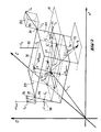
- FIG. 2 shows the L * a * b * color space with the color vector i for the actual color location I of an area scanned on the printing sheet 40, in particular a color measuring area 41, which has a gray field or another one that is particularly adapted to the image content on the printing sheet 40 Grid or solid field can be to perform an optimal correction of the color and brightness components at the same time.
- the maximum permissible density differences delta D ymax and delta D ymin are shown in FIG. 2.
- the maximum permissible density differences result from the differences between the actual density D actual and the permissible limit densities D max and D min for the printing inks involved in each case.
- the limit values for the solid ink density result, for example, from the requirements for a sufficient relative pressure contrast.
- the correction vectors c, m and y span the correction color space 50 around the current actual color location I. Although they are usually not at right angles to one another, this is shown in FIG. 2 for the sake of simplicity. It is also assumed that within a sufficiently small correction color space around the actual color location there is a linear approximation of the relationships between the color location coordinates and the densities.
- target color locations S 1 to S6 are shown in FIG. 2 to illustrate the control strategy according to the invention, each of which represents a special case and of course only one of each of the predetermined target color location S is instead of the actual color locus I should have been reached when printing the printed sheet 40.
- the target color location S 1 whose color distance from the actual color location I is illustrated by the color distance vector 51, lies within the correction color space 50, which represents a control body.
- the correction color space 50 which represents a control body.
- Control strategies are explained below for those cases in which a target color location S cannot be achieved as a result of predetermined color density limits or other restrictions.
- a replacement target color location i.e. achievable target color location S 'or S ⁇ can be controlled, which is characterized by a least disturbing color difference for the viewer.
- the target color location S lies outside the correction color space 50, it is possible to select the penetration point of the color distance vector through the affected side surface or boundary surface of the correction color space 50 as the achievable target color location S ⁇ .
- Fig. 2 it is shown how in this way at a target color location S2 an achievable target color location S ⁇ 2nd is obtained.
- the attainable target color locus S ⁇ 2nd lies on the intersection of the color distance vector 52 with the side surface 60 of the correction color space 50.
- the strategy of choosing the point of penetration of the color distance vector between the actual color location and the target color location has the advantage of a simple calculation and is an approximation.
- the recognizable in Fig. 2 distance between the target color location S2 and the achievable target color location S ⁇ 2nd represents the uncorrected or uncorrectable color difference of the. Since the target color location S2 lies in a spatial area, for the spatial points of which there is a solder on the side surface 60, there is a smaller, non-correctable color difference corresponding to the length of the solder 62 on the side surface 60 when the target color location S that can be achieved ′ 2nd the base point of the solder 62 on the side surface 60 is selected. In Fig. 2, the right angle and the plane 61 are shown, in which the solder 62 and the target color location S2 and the achievable target color location S ′ 2nd lie.
- the color distance vector between the actual color location I and the achievable target color location S is ′ 2nd not shown. If with the help of the computer by analytically determining the minimum distance from the correction color space 50, the achievable target color location S ′ 2nd has been determined, the necessary density difference vector is calculated for this with the aid of the sensitivity matrix A.
- the smallest distance between the target color location S2 and the closest boundary surface of the correction color space 50, i.e. of the side surface 60 was determined in the exemplary embodiment discussed by determining the base point of a solder 62. Depending on the position of the target color location, however, it is not possible to plumb one of the boundary surfaces of the correction color space 50. In such cases, the point with the smallest distance from the target color location S is determined in a different way.
- the target color locus shifts so far that it comes to lie outside the spatial area, for that Points each have a solder on the adjacent side surface 60, as is the case, for example, for the target color location S 3, so that an achievable target color location S is determined ′ 3rd by determining the solder 73 on the adjacent edge 70 of the correction color space 50 and as the achievable target color location S ′ 3rd the intersection of the solder 73 with the edge 70 of the correction color space 70 is selected.
- the target color locus S4 in FIG. 2 lies at a point that does not allow the construction of a solder on a side surface or on an edge of the control body or correction color space 50. For this reason, for the achievable target color locus S ′ 4th the adjacent corner 80 of the correction color space 50 is selected, since this point has the smallest distance of all points on the surface of the correction color space 50 from the desired color location S4. The distance between the target color location S that can be achieved in this way ′ 4th
- the actual target color location S4 is illustrated in FIG. 2 by the connecting line 84, with a cuboid 85 being drawn in to illustrate the spatial position of the target color location S4, the diagonal of which is formed by the connecting line 84.
- color component errors can be weighted and corrected more than the brightness errors.
- the color component errors can be completely corrected, which is illustrated by the target color location S5 in FIG. 2.
- the attainable target color location S assigned to the target color location S5 ′ 5 is obtained in such a way that a parallel to the L * axis is constructed by S5, which intersects the top surface 90 of the correction color space 50 which points essentially upward in the direction of the L * axis and thereby the achievable target color location S ′ 5 Are defined.
- the attainable target color locus S ′ 5 is shifted relative to the (not shown) penetration point of a solder from the target color location S5 on the top surface 90 in such a way that the color coordinates a * and b * of the target color location S ′ 5 agree with those of the target color locus S5, it being accepted that an additional deviation in the brightness coordinate L * occurs compared to the choice of the piercing point of the solder.
- the color distance vector 95 between the target color location S5 and the achievable target color location S. ′ 5 is longer than the solder of S5 on top surface 90, but its components for a * and b * are zero.
- the control strategy according to the invention thus proposes to preferably try to reach the correction color space 50 starting from a target color location by determining an achievable target color location by shifting the actual target color location parallel to the L * axis.
- the closest corner 97 of the correction color space 50 is selected as the achievable target color location, but rather the point S, by negotiating a larger brightness error against lower color component errors ′ 6 on the surface of the correction color space 50, which lies on a plane which extends parallel to the a * and b * coordinates at a distance from the target color location S6, which is defined by the largest permitted brightness error, and which is the smallest distance from the Parallels to the L * axis through the target color locus S6.
- the intersection of this plane with the parallel to the L * axis is provided in FIG. 2 with the reference symbol 98.
- the determination of the achievable target color locus S ′ 6 can also be done in such a way that, starting from the intersection 98, the base point of the solder on the edge 99 is determined in accordance with the strategy applied at the target color location S3.
- the person skilled in the art will recognize from the above statements that the linear compression of the L * axis is not only possible separately, but also in combination with the constructions discussed using the target color locations S2, S3 and S4.
- the calculations required for this are carried out by the computer of the measured value processing of the printing system. Which strategy is chosen depends on the one hand on the relative position of the target color locus S to the correction color space 50 and on the other hand on the type of measuring field and the objectives. It is useful if the operator of the printing system can specify the strategy to be selected in several ways.
- the achievable target color location on the surface of the correction color space 50 is determined, this is selected for the control on the minimum color distance, the density difference vector being obtained according to the following equation:
- ⁇ D c , ⁇ D m and ⁇ D y are the components of the solid tone change vector.
- the components of the color distance vector between the actual color location and the achievable target color location are designated by ⁇ L, ⁇ a and ⁇ b.
- the matrix containing the partial derivatives of the solid color densities according to the components of the color space is the sensitivity matrix A already mentioned.
- the control strategies discussed can also be used for measuring fields in which fewer than three printing inks are printed.
- the correction color space is reduced to a parallelogram and for a single-color field to a distance in Color space.
- the control strategies and calculations described above are applied analogously in such cases. All that needs to be done is to set the correction vectors of the non-existent colors to zero.
- the target color locations are practically always outside of the area or section-shaped correction area. For this reason, the strategies discussed above for finding an achievable target color location are a prerequisite for optimal color control.
Landscapes
- Engineering & Computer Science (AREA)
- Quality & Reliability (AREA)
- Facsimile Image Signal Circuits (AREA)
- Inking, Control Or Cleaning Of Printing Machines (AREA)
- Spectrometry And Color Measurement (AREA)
Claims (11)
Applications Claiming Priority (2)
| Application Number | Priority Date | Filing Date | Title |
|---|---|---|---|
| CH492287 | 1987-12-16 | ||
| CH4922/87 | 1987-12-16 |
Publications (2)
| Publication Number | Publication Date |
|---|---|
| EP0321402A1 EP0321402A1 (fr) | 1989-06-21 |
| EP0321402B1 true EP0321402B1 (fr) | 1991-10-16 |
Family
ID=4284860
Family Applications (1)
| Application Number | Title | Priority Date | Filing Date |
|---|---|---|---|
| EP88810844A Expired - Lifetime EP0321402B1 (fr) | 1987-12-16 | 1988-12-07 | Procédé de commande ou du réglage de l'encrage d'une presse à imprimer |
Country Status (4)
| Country | Link |
|---|---|
| US (1) | US4967379A (fr) |
| EP (1) | EP0321402B1 (fr) |
| JP (1) | JPH01208136A (fr) |
| DE (1) | DE3865653D1 (fr) |
Families Citing this family (41)
| Publication number | Priority date | Publication date | Assignee | Title |
|---|---|---|---|---|
| JPH0264875A (ja) * | 1988-08-31 | 1990-03-05 | Toshiba Corp | カラー画像の高速彩度変換装置 |
| DE3812099C2 (de) * | 1988-04-12 | 1995-01-26 | Heidelberger Druckmasch Ag | Verfahren zur Farbsteuerung einer Offsetdruckmaschine |
| KR900702340A (ko) * | 1988-07-14 | 1990-12-06 | 원본미기재 | 컴퓨터화된 칼라매칭방법과 장치 |
| DE3830731A1 (de) * | 1988-09-09 | 1990-03-22 | Heidelberger Druckmasch Ag | Vorrichtung zur farbmessung |
| DE3903981C2 (de) * | 1989-02-10 | 1998-04-09 | Heidelberger Druckmasch Ag | Verfahren zur Regelung der Farbfüllung bei einer Druckmaschine |
| DE59003421D1 (de) * | 1989-07-14 | 1993-12-16 | Gretag Ag | Verfahren zur Bestimmung der Farbmasszahldifferenzen zwischen zwei mit hilfe einer Druckmaschine gedruckten Rasterfeldern sowie Verfahren zur Farbsteuerung oder Farbregelung des Druckes einer Druckmaschine. |
| EP0421003B1 (fr) * | 1989-10-02 | 1994-12-07 | grapho metronic Mess- und Regeltechnik GmbH & Co. | Méthode pour contrôler l'apport d'encre dans une machine d'impression |
| DE4005558A1 (de) * | 1990-02-22 | 1991-09-19 | Roland Man Druckmasch | Verfahren zur prozessdiagnose einer rotationsdruckmaschine anhand von remissionen von vollton- und rastertonfeldern |
| DE4104537C2 (de) * | 1991-02-14 | 1999-05-12 | Roland Man Druckmasch | Verfahren zur Steuerung einer Farbführung einer Offset-Druckmaschine |
| US5540148A (en) * | 1991-09-19 | 1996-07-30 | Lintec Co., Ltd. | Printing device and die-cutting device |
| EP0736381B1 (fr) * | 1991-09-19 | 1999-01-27 | LINTEC Corporation | Dispositif de découpage à l'emporte-pièce pour un dispositif d'impression |
| US5841955A (en) * | 1991-12-02 | 1998-11-24 | Goss Graphic Systems, Inc. | Control system for a printing press |
| US5224421A (en) * | 1992-04-28 | 1993-07-06 | Heidelberg Harris, Inc. | Method for color adjustment and control in a printing press |
| DE4229267A1 (de) * | 1992-09-02 | 1994-03-03 | Roland Man Druckmasch | Verfahren zur Steuerung des Druckprozesses auf einer autotypisch arbeitenden Druckmaschine, insbesondere Bogenoffsetdruckmaschine |
| US5500921A (en) * | 1992-10-05 | 1996-03-19 | Canon Information Systems, Inc. | Method and apparatus for printing high fidelity color reproductions of colors displayed on a monitor |
| US5438649A (en) * | 1992-10-05 | 1995-08-01 | Canon Information Systems, Inc. | Color printing method and apparatus which compensates for Abney effect |
| US5299291A (en) * | 1992-10-05 | 1994-03-29 | Canon Information Systems | Color printing method and apparatus using an out-of-gamut color table |
| US5365847A (en) * | 1993-09-22 | 1994-11-22 | Rockwell International Corporation | Control system for a printing press |
| DE4402784C2 (de) * | 1994-01-31 | 2001-05-31 | Wifag Maschf | Messfeldgruppe und Verfahren zur Qualitätsdatenerfassung unter Verwendung der Messfeldgruppe |
| DE4402828C2 (de) * | 1994-01-31 | 2001-07-12 | Wifag Maschf | Messfeldgruppe und Verfahren zur Qualitätsdatenerfassung unter Verwendung der Messfeldgruppe |
| DE4415486C2 (de) * | 1994-05-03 | 1998-06-04 | Heidelberger Druckmasch Ag | Verfahren zur Bestimmung der zulässigen Toleranzen für die Steuerung oder Regelung der Farbgebung an einer Druckmaschine |
| JPH07333925A (ja) * | 1994-06-14 | 1995-12-22 | Canon Inc | 画像調整装置および画像再現装置 |
| US5812705A (en) * | 1995-02-28 | 1998-09-22 | Goss Graphic Systems, Inc. | Device for automatically aligning a production copy image with a reference copy image in a printing press control system |
| US5767980A (en) * | 1995-06-20 | 1998-06-16 | Goss Graphic Systems, Inc. | Video based color sensing device for a printing press control system |
| US5805280A (en) * | 1995-09-28 | 1998-09-08 | Goss Graphic Systems, Inc. | Control system for a printing press |
| EP0765748A3 (fr) * | 1995-09-29 | 1997-08-13 | Goss Graphics Systems Inc | Dispositif pour l'alignement d'images dans un système de contrÔle pour une machine à imprimer |
| US5903712A (en) * | 1995-10-05 | 1999-05-11 | Goss Graphic Systems, Inc. | Ink separation device for printing press ink feed control |
| US5759030A (en) * | 1996-01-02 | 1998-06-02 | Lj Laboratories, L.L.C. | Method for determing optical characteristics of teeth |
| US6254385B1 (en) | 1997-01-02 | 2001-07-03 | Lj Laboratories, Llc | Apparatus and method for measuring optical characteristics of teeth |
| US6388768B2 (en) | 1996-04-22 | 2002-05-14 | Minolta Co., Ltd. | Image forming apparatus which excels in reproducibility of colors, fine lines and gradations even in a copy made from a copied image |
| US6072901A (en) * | 1997-05-30 | 2000-06-06 | Polaroid Corporation | System and method for deriving an invertible relationship between color spaces where the intrinsic mapping is one-to-many for use in a color profile production system |
| US5967050A (en) * | 1998-10-02 | 1999-10-19 | Quad/Tech, Inc. | Markless color control in a printing press |
| US6567186B1 (en) * | 1998-10-27 | 2003-05-20 | Hewlett-Packard Company | Method for determining gray values in a printer |
| US6947175B1 (en) * | 2000-07-31 | 2005-09-20 | Xerox Corporation | Method and system for adjusting color mixing due to substrate characteristics |
| JP3943873B2 (ja) * | 2001-07-26 | 2007-07-11 | 大日本スクリーン製造株式会社 | 印刷機におけるインキおよび水の供給量制御装置、ならびにそれを備えた印刷システム |
| JP2009178883A (ja) * | 2008-01-30 | 2009-08-13 | Ryobi Ltd | カラー印刷機の印刷画像品質管理方法及び印刷画像品質管理装置 |
| US8532371B2 (en) * | 2010-10-04 | 2013-09-10 | Datacolor Holding Ag | Method and apparatus for evaluating color in an image |
| US9076068B2 (en) | 2010-10-04 | 2015-07-07 | Datacolor Holding Ag | Method and apparatus for evaluating color in an image |
| AT512440B1 (de) * | 2012-01-20 | 2014-08-15 | Ait Austrian Inst Technology | Farbtreueprüfung |
| JP5985241B2 (ja) * | 2012-04-27 | 2016-09-06 | 株式会社ミマキエンジニアリング | 印刷装置及び印刷方法 |
| DE102017202937B4 (de) * | 2017-02-23 | 2019-08-08 | Koenig & Bauer Ag | Verfahren zur Steuerung einer mit einer Druckmaschine datentechnisch verbundenen Anzeigeeinrichtung |
Family Cites Families (47)
| Publication number | Priority date | Publication date | Assignee | Title |
|---|---|---|---|---|
| US3322025A (en) * | 1962-05-17 | 1967-05-30 | William C Dauser | Color control method |
| US4151796A (en) * | 1973-04-02 | 1979-05-01 | Heidelberger Druckmaschinen Aktiengesellschaft | Device for automatically controlling deviations in liquid feed in offset presses |
| US3958509A (en) * | 1974-06-13 | 1976-05-25 | Harris Corporation | Image scan and ink control system |
| US4210078A (en) * | 1974-06-24 | 1980-07-01 | M.A.N.-Roland Druckmaschinen Aktiengesellschaft | Apparatus for use on printing presses to insure optimum color density and to assist in making corrective adjustment |
| US3995958A (en) * | 1975-07-21 | 1976-12-07 | Hallmark Cards, Incorporated | Automatic densitometer and method of color control in multi-color printing |
| US4003660A (en) * | 1975-12-03 | 1977-01-18 | Hunter Associates Laboratory, Inc. | Sensing head assembly for multi-color printing press on-line densitometer |
| US4022534A (en) * | 1976-03-23 | 1977-05-10 | Kollmorgen Corporation | Reflectometer optical system |
| US4256131A (en) * | 1976-07-14 | 1981-03-17 | Sentrol Systems Ltd. | Feedback color control system |
| DE2728738B2 (de) * | 1977-06-25 | 1979-05-10 | Roland Offsetmaschinenfabrik Faber & Schleicher Ag, 6050 Offenbach | Eulrichtung zur Kontrolle und Regelung der Farbgebung an Druckmaschinen |
| JPS6018929B2 (ja) * | 1977-10-13 | 1985-05-13 | スガ試験機株式会社 | 色表示装置 |
| DE2747527A1 (de) * | 1977-10-22 | 1979-04-26 | Agfa Gevaert Ag | Verfahren und vorrichtung zum bestimmen der kopierlichtmengen beim kopieren von farbvorlagen |
| JPS5952069B2 (ja) * | 1977-12-15 | 1984-12-18 | 凸版印刷株式会社 | 使用インキ量予測装置 |
| US4183657A (en) * | 1978-04-10 | 1980-01-15 | International Business Machines Corporation | Dynamic reference for an image quality control system |
| US4210818A (en) * | 1978-06-07 | 1980-07-01 | Harris Corporation | Apparatus for determining image areas for printing |
| US4289405A (en) * | 1978-10-13 | 1981-09-15 | Tobias Philip E | Color monitoring system for use in creating colored displays |
| DE2950606A1 (de) * | 1979-12-15 | 1981-06-19 | M.A.N.- Roland Druckmaschinen AG, 6050 Offenbach | Vorrichtung zur zonenweisen optoelektronischen messung der flaechendeckung einer druckvorlage |
| JPS5698634A (en) * | 1980-01-09 | 1981-08-08 | Dainippon Printing Co Ltd | Printed matter testing device |
| DE3007421A1 (de) * | 1980-02-27 | 1981-09-03 | Windmöller & Hölscher, 4540 Lengerich | Verfahren zur herstellung eines vorlagengetreuen farbengemisches, insbesondere einer farbe eines mehrfarbendruckes |
| IT1135365B (it) * | 1980-02-27 | 1986-08-20 | Roland Man Druckmasch | Procedimento per determinare singoli componenti cromatici in una stampa in plicromia per mezzo d'un densitometro |
| US4310248A (en) * | 1980-04-24 | 1982-01-12 | Meredith Nolan J | Color control system |
| DE3024773A1 (de) * | 1980-06-30 | 1982-01-28 | Grapho-Metronic Meß- und Regeltechnik GmbH & Co, KG, 8000 München | Verfahren und einrichtung zur kontrolle und zum steuern der farbgebung einer mehrfarben-druckmaschine |
| US4309496A (en) * | 1980-09-10 | 1982-01-05 | Miller Dennis B | Method for optimization of image reproduction processes |
| US4439038A (en) * | 1981-03-03 | 1984-03-27 | Sentrol Systems Ltd. | Method and apparatus for measuring and controlling the color of a moving web |
| US4505589A (en) * | 1981-04-03 | 1985-03-19 | Gretag Aktiengesellschaft | Process and apparatus for the colorimetric analysis of printed material |
| JPS57208422A (en) * | 1981-06-18 | 1982-12-21 | Fuji Photo Film Co Ltd | Hue judging device |
| US4512662A (en) * | 1981-07-06 | 1985-04-23 | Tobias Philip E | Plate scanner for printing plates |
| DE3127381A1 (de) * | 1981-07-10 | 1983-01-27 | Salvat Editores, S.A., Barcelona | Messorgane fuer im geschlossenen kreis arbeitende systeme zur ueberwachung und korrektur des drucks bei offset-druckmaschinen |
| GB2115145B (en) * | 1981-07-29 | 1986-05-29 | Dainippon Printing Co Ltd | Method and device for inspecting printed matter |
| JPS5848054A (ja) * | 1981-09-17 | 1983-03-19 | Kotobuki Seihan Insatsu Kk | オフセツト印刷用ps版の種類識別方式 |
| JPS5848177A (ja) * | 1981-09-18 | 1983-03-22 | Toshiba Corp | 特定色彩パタ−ンの検出装置 |
| JPS58105007A (ja) * | 1981-12-17 | 1983-06-22 | Toshiba Corp | 画像面積測定装置 |
| DE3209483A1 (de) * | 1982-03-16 | 1983-09-29 | Windmöller & Hölscher, 4540 Lengerich | Verfahren zum automatischen einstellen der von flexodruckmaschinen fuer den vierfarbendruck ausgedrucktenfarben |
| US4403866A (en) * | 1982-05-07 | 1983-09-13 | E. I. Du Pont De Nemours And Company | Process for making paints |
| DE3220360A1 (de) * | 1982-05-29 | 1983-12-01 | Heidelberger Druckmaschinen Ag, 6900 Heidelberg | Einrichtung zur beeinflussung der farbgebung an druckmaschinen |
| DE3220800C2 (de) * | 1982-06-03 | 1986-10-30 | M.A.N.- Roland Druckmaschinen AG, 6050 Offenbach | Vorrichtung zur Abtastung von Druckplatten |
| DE3314333A1 (de) * | 1983-04-20 | 1984-10-25 | Albert-Frankenthal Ag, 6710 Frankenthal | Verfahren und vorrichtung zur regelung der farbzufuhr zu den farbwerken einer mehrfarbendruckmaschine |
| JPS59206839A (ja) * | 1983-05-10 | 1984-11-22 | Toppan Printing Co Ltd | 網点面積率入力装置 |
| US4553033A (en) * | 1983-08-24 | 1985-11-12 | Xerox Corporation | Infrared reflectance densitometer |
| US4706206A (en) * | 1983-09-20 | 1987-11-10 | Kollmorgen Technologies Corporation | Color printing control using halftone control areas |
| DE3468650D1 (en) * | 1983-11-04 | 1988-02-18 | Gretag Ag | Method and device for rating the printing quality and/or controlling the ink supply in an offset printing machine, and offset printing machine with such a device |
| DE3468367D1 (en) * | 1983-11-04 | 1988-02-11 | Gretag Ag | Method and device for judging the printing quality of a printed object, preferably printed by an offset printing machine, and offset printing machine provided with such a device |
| ATE58336T1 (de) * | 1983-12-19 | 1990-11-15 | Gretag Ag | Verfahren, vorrichtung und farbmessstreifen fuer die druckqualitaetsbeurteilung. |
| EP0196431B1 (fr) * | 1985-03-21 | 1992-11-11 | Felix Brunner | Procédé, dispositif de réglage et moyens auxiliaires pour l'obtention d'un résultat d'impression uniforme au moyen d'une machine d'impression offset polychrome fonctionnant suivant le procédé de similigravure |
| US4745555A (en) * | 1985-09-06 | 1988-05-17 | Burlington Industries, Inc. | Method and apparatus for inventory control to optimize usage of colored fabric |
| DE3666554D1 (en) * | 1985-12-10 | 1989-11-30 | Heidelberger Druckmasch Ag | Process for controlling the application of colours in a printing machine, printing device equipped therewith and measuring device for such a printing device |
| US4884221A (en) * | 1986-04-14 | 1989-11-28 | Minolta Camera Kabushiki Kaisha | Color measuring apparatus |
| US4813000A (en) * | 1986-07-09 | 1989-03-14 | Jones-Blair Company | Computerized color matching |
-
1988
- 1988-12-05 US US07/279,776 patent/US4967379A/en not_active Expired - Fee Related
- 1988-12-07 EP EP88810844A patent/EP0321402B1/fr not_active Expired - Lifetime
- 1988-12-07 DE DE8888810844T patent/DE3865653D1/de not_active Expired - Fee Related
- 1988-12-16 JP JP63318343A patent/JPH01208136A/ja active Pending
Also Published As
| Publication number | Publication date |
|---|---|
| DE3865653D1 (de) | 1991-11-21 |
| US4967379A (en) | 1990-10-30 |
| EP0321402A1 (fr) | 1989-06-21 |
| JPH01208136A (ja) | 1989-08-22 |
Similar Documents
| Publication | Publication Date | Title |
|---|---|---|
| EP0321402B1 (fr) | Procédé de commande ou du réglage de l'encrage d'une presse à imprimer | |
| EP0324718B1 (fr) | Procédé et dispositif pour régler l'encre dans une machine à imprimer | |
| EP0408507B1 (fr) | Méthode de détermination des écarts de couleur entre deux surfaces tramées imprimées avec une machine d'impression ainsi que méthode de commande ou réglage de l'impression couleurs d'une machine à imprimer | |
| EP0143744B1 (fr) | Procédé et dispositif d'analyse de qualité d'impression et/ou de réglage d'encre dans une rotative offset et rotative offset équipée d'un tel dispositif | |
| EP0255586B1 (fr) | Procédé et dispositif pour influencer l'encrage d'une surface encrée dans une machine à imprimer | |
| EP0337148B1 (fr) | Procédé de commande de l'encrage d'une machine d'impression | |
| DE2814903C2 (fr) | ||
| DE4012608C2 (fr) | ||
| DE69510710T2 (de) | Farbdruck mit erweitertem Dichteumfang | |
| DE2637055C2 (de) | Farbkorrekturanordnung für Reproduktionszwecke | |
| DE4309877C2 (de) | Verfahren und Einrichtung zur Analyse von Farbstichen in Farbvorlagen | |
| EP0914945B1 (fr) | Procédé pour régler l'encrage dans une machine d'impression | |
| DE19515499C2 (de) | Verfahren zur simultanen Mehrfarbregelung beim Drucken | |
| EP0825023B1 (fr) | Procédé pour déterminer des données de reglage pour la commande d'une machine à imprimer | |
| DE10017554A1 (de) | Vorrichtung und Verfahren zum Steuern der Farbzufuhr bei Druckmaschinen | |
| EP0836941B1 (fr) | Groupe de champs de mesure et procédé pour la saisie des données de qualité dans les éditions (tirages) d'impression polychrome | |
| EP1237355A2 (fr) | Procédé de détermination d'un profil de couleurs pour l'impression au moyen de plusieurs couleurs d'impression | |
| DE4240077C2 (de) | Verfahren zur zonalen Steuerung/Regelung der Farbführung in einer Druckmaschine | |
| DE3714179C2 (fr) | ||
| EP0916491B1 (fr) | Procédé pour déterminer des gradients colorimétriques | |
| EP3918780B1 (fr) | Tête d'impression numérique | |
| DE19830487A1 (de) | Verfahren zur Ermittlung von Flächendeckungen in einem Druckbild | |
| DE19638967C2 (de) | Messfeldgruppe und Verfahren zur Erfassung von optisch drucktechnischen Größen im Mehrfarben-Auflagendruck | |
| DE19701967C2 (de) | Verfahren zur Bestimmung der farblichen Erscheinung sowie entsprechende Vorrichtung | |
| DE19639014A1 (de) | Messfeldgruppe und Verfahren zur Erfassung von Qualitätsdaten im Mehrfarben-Auflagendruck |
Legal Events
| Date | Code | Title | Description |
|---|---|---|---|
| PUAI | Public reference made under article 153(3) epc to a published international application that has entered the european phase |
Free format text: ORIGINAL CODE: 0009012 |
|
| 17P | Request for examination filed |
Effective date: 19881209 |
|
| AK | Designated contracting states |
Kind code of ref document: A1 Designated state(s): CH DE FR GB IT LI |
|
| 17Q | First examination report despatched |
Effective date: 19901115 |
|
| ITF | It: translation for a ep patent filed | ||
| GRAA | (expected) grant |
Free format text: ORIGINAL CODE: 0009210 |
|
| AK | Designated contracting states |
Kind code of ref document: B1 Designated state(s): CH DE FR GB IT LI |
|
| ET | Fr: translation filed | ||
| REF | Corresponds to: |
Ref document number: 3865653 Country of ref document: DE Date of ref document: 19911121 |
|
| GBT | Gb: translation of ep patent filed (gb section 77(6)(a)/1977) | ||
| PLBE | No opposition filed within time limit |
Free format text: ORIGINAL CODE: 0009261 |
|
| STAA | Information on the status of an ep patent application or granted ep patent |
Free format text: STATUS: NO OPPOSITION FILED WITHIN TIME LIMIT |
|
| 26N | No opposition filed | ||
| PGFP | Annual fee paid to national office [announced via postgrant information from national office to epo] |
Ref country code: GB Payment date: 20001115 Year of fee payment: 13 |
|
| PGFP | Annual fee paid to national office [announced via postgrant information from national office to epo] |
Ref country code: CH Payment date: 20001120 Year of fee payment: 13 |
|
| PGFP | Annual fee paid to national office [announced via postgrant information from national office to epo] |
Ref country code: FR Payment date: 20001204 Year of fee payment: 13 |
|
| PGFP | Annual fee paid to national office [announced via postgrant information from national office to epo] |
Ref country code: DE Payment date: 20001213 Year of fee payment: 13 |
|
| PG25 | Lapsed in a contracting state [announced via postgrant information from national office to epo] |
Ref country code: GB Free format text: LAPSE BECAUSE OF NON-PAYMENT OF DUE FEES Effective date: 20011207 |
|
| PG25 | Lapsed in a contracting state [announced via postgrant information from national office to epo] |
Ref country code: LI Free format text: LAPSE BECAUSE OF NON-PAYMENT OF DUE FEES Effective date: 20011231 Ref country code: CH Free format text: LAPSE BECAUSE OF NON-PAYMENT OF DUE FEES Effective date: 20011231 |
|
| REG | Reference to a national code |
Ref country code: GB Ref legal event code: IF02 |
|
| PG25 | Lapsed in a contracting state [announced via postgrant information from national office to epo] |
Ref country code: DE Free format text: LAPSE BECAUSE OF NON-PAYMENT OF DUE FEES Effective date: 20020702 |
|
| GBPC | Gb: european patent ceased through non-payment of renewal fee |
Effective date: 20011207 |
|
| REG | Reference to a national code |
Ref country code: CH Ref legal event code: PL |
|
| PG25 | Lapsed in a contracting state [announced via postgrant information from national office to epo] |
Ref country code: FR Free format text: LAPSE BECAUSE OF NON-PAYMENT OF DUE FEES Effective date: 20020830 |
|
| REG | Reference to a national code |
Ref country code: FR Ref legal event code: ST |
|
| PG25 | Lapsed in a contracting state [announced via postgrant information from national office to epo] |
Ref country code: IT Free format text: LAPSE BECAUSE OF NON-PAYMENT OF DUE FEES;WARNING: LAPSES OF ITALIAN PATENTS WITH EFFECTIVE DATE BEFORE 2007 MAY HAVE OCCURRED AT ANY TIME BEFORE 2007. THE CORRECT EFFECTIVE DATE MAY BE DIFFERENT FROM THE ONE RECORDED. Effective date: 20051207 |