EP0321437A2 - Procédé pour la fabrication d'un outil de découpe à simple ou à double tranchant pour les matériaux non métalliques - Google Patents
Procédé pour la fabrication d'un outil de découpe à simple ou à double tranchant pour les matériaux non métalliques Download PDFInfo
- Publication number
- EP0321437A2 EP0321437A2 EP88890286A EP88890286A EP0321437A2 EP 0321437 A2 EP0321437 A2 EP 0321437A2 EP 88890286 A EP88890286 A EP 88890286A EP 88890286 A EP88890286 A EP 88890286A EP 0321437 A2 EP0321437 A2 EP 0321437A2
- Authority
- EP
- European Patent Office
- Prior art keywords
- knife
- reinforcing plate
- groove
- punching
- plate
- Prior art date
- Legal status (The legal status is an assumption and is not a legal conclusion. Google has not performed a legal analysis and makes no representation as to the accuracy of the status listed.)
- Ceased
Links
- 238000004519 manufacturing process Methods 0.000 title claims abstract description 10
- 238000000034 method Methods 0.000 title claims description 13
- 239000000463 material Substances 0.000 title claims description 4
- 230000003014 reinforcing effect Effects 0.000 claims abstract description 29
- 238000004080 punching Methods 0.000 claims abstract description 26
- 239000007769 metal material Substances 0.000 claims abstract description 6
- 239000010985 leather Substances 0.000 claims abstract description 4
- 239000004753 textile Substances 0.000 claims abstract description 4
- 239000000123 paper Substances 0.000 claims abstract description 3
- 239000004033 plastic Substances 0.000 claims description 4
- 229920003023 plastic Polymers 0.000 claims description 4
- 238000003780 insertion Methods 0.000 claims description 3
- 230000037431 insertion Effects 0.000 claims description 3
- 238000003466 welding Methods 0.000 claims description 3
- 238000005516 engineering process Methods 0.000 claims description 2
- 238000005476 soldering Methods 0.000 claims description 2
- 238000005520 cutting process Methods 0.000 description 10
- 230000002787 reinforcement Effects 0.000 description 7
- 229910000831 Steel Inorganic materials 0.000 description 4
- 239000010959 steel Substances 0.000 description 4
- 238000009434 installation Methods 0.000 description 3
- 238000003825 pressing Methods 0.000 description 2
- 239000007787 solid Substances 0.000 description 2
- 239000004698 Polyethylene Substances 0.000 description 1
- NIXOWILDQLNWCW-UHFFFAOYSA-N acrylic acid group Chemical group C(C=C)(=O)O NIXOWILDQLNWCW-UHFFFAOYSA-N 0.000 description 1
- 238000005452 bending Methods 0.000 description 1
- 239000011111 cardboard Substances 0.000 description 1
- 238000010276 construction Methods 0.000 description 1
- 238000010924 continuous production Methods 0.000 description 1
- 238000007796 conventional method Methods 0.000 description 1
- 230000002349 favourable effect Effects 0.000 description 1
- 239000002184 metal Substances 0.000 description 1
- -1 polyethylene Polymers 0.000 description 1
- 229920000573 polyethylene Polymers 0.000 description 1
- 229920000098 polyolefin Polymers 0.000 description 1
- 239000002023 wood Substances 0.000 description 1
Images

Classifications
-
- B—PERFORMING OPERATIONS; TRANSPORTING
- B21—MECHANICAL METAL-WORKING WITHOUT ESSENTIALLY REMOVING MATERIAL; PUNCHING METAL
- B21D—WORKING OR PROCESSING OF SHEET METAL OR METAL TUBES, RODS OR PROFILES WITHOUT ESSENTIALLY REMOVING MATERIAL; PUNCHING METAL
- B21D37/00—Tools as parts of machines covered by this subclass
- B21D37/20—Making tools by operations not covered by a single other subclass
- B21D37/205—Making cutting tools
-
- B—PERFORMING OPERATIONS; TRANSPORTING
- B23—MACHINE TOOLS; METAL-WORKING NOT OTHERWISE PROVIDED FOR
- B23P—METAL-WORKING NOT OTHERWISE PROVIDED FOR; COMBINED OPERATIONS; UNIVERSAL MACHINE TOOLS
- B23P15/00—Making specific metal objects by operations not covered by a single other subclass or a group in this subclass
- B23P15/28—Making specific metal objects by operations not covered by a single other subclass or a group in this subclass cutting tools
- B23P15/40—Making specific metal objects by operations not covered by a single other subclass or a group in this subclass cutting tools shearing tools
-
- B—PERFORMING OPERATIONS; TRANSPORTING
- B26—HAND CUTTING TOOLS; CUTTING; SEVERING
- B26F—PERFORATING; PUNCHING; CUTTING-OUT; STAMPING-OUT; SEVERING BY MEANS OTHER THAN CUTTING
- B26F1/00—Perforating; Punching; Cutting-out; Stamping-out; Apparatus therefor
- B26F1/38—Cutting-out; Stamping-out
- B26F1/44—Cutters therefor; Dies therefor
- B26F1/46—Loose press knives
-
- B—PERFORMING OPERATIONS; TRANSPORTING
- B26—HAND CUTTING TOOLS; CUTTING; SEVERING
- B26F—PERFORATING; PUNCHING; CUTTING-OUT; STAMPING-OUT; SEVERING BY MEANS OTHER THAN CUTTING
- B26F1/00—Perforating; Punching; Cutting-out; Stamping-out; Apparatus therefor
- B26F1/38—Cutting-out; Stamping-out
- B26F1/40—Cutting-out; Stamping-out using a press, e.g. of the ram type
-
- B—PERFORMING OPERATIONS; TRANSPORTING
- B26—HAND CUTTING TOOLS; CUTTING; SEVERING
- B26F—PERFORATING; PUNCHING; CUTTING-OUT; STAMPING-OUT; SEVERING BY MEANS OTHER THAN CUTTING
- B26F1/00—Perforating; Punching; Cutting-out; Stamping-out; Apparatus therefor
- B26F1/38—Cutting-out; Stamping-out
- B26F1/44—Cutters therefor; Dies therefor
- B26F2001/4463—Methods and devices for rule setting, fixation, preparing cutting dies
-
- Y—GENERAL TAGGING OF NEW TECHNOLOGICAL DEVELOPMENTS; GENERAL TAGGING OF CROSS-SECTIONAL TECHNOLOGIES SPANNING OVER SEVERAL SECTIONS OF THE IPC; TECHNICAL SUBJECTS COVERED BY FORMER USPC CROSS-REFERENCE ART COLLECTIONS [XRACs] AND DIGESTS
- Y10—TECHNICAL SUBJECTS COVERED BY FORMER USPC
- Y10T—TECHNICAL SUBJECTS COVERED BY FORMER US CLASSIFICATION
- Y10T83/00—Cutting
- Y10T83/929—Tool or tool with support
- Y10T83/9295—Work supported tool [e.g., clicker die]
Definitions
- the invention relates to a method for producing a one- or two-sided punching knife for non-metallic materials, such as leather, textiles, paper etc. with an internal groove and a reinforcing plate engaging in the groove, and a steel strip for carrying out the method.
- Punch knives of the type to be manufactured are known from DE-OS 1 511 073 and US Pat. No. 2,298,041. For example, they are bent from steel strip, possibly around the finished reinforcement plate.
- the reinforcement plates made of wood, cardboard, plastic or metal are manufactured in a suitable manner, for example by sawing, then inserted into the knife - or the knife is bent around them - and connected to it.
- Punching knives are also known which have no reinforcing plates but instead have rod-shaped stiffening elements in the interior of the knife.
- the attachment of the reinforcing bars, usually by welding, is at least as complex and time-consuming as the insertion of a reinforcing plate.
- the latter has the advantage of stiffening and supporting the punch knife evenly over the entire circumference.
- the invention has set itself the task of specifying a manufacturing method for a punching knife of the type mentioned at the outset which is simple and inexpensive to carry out. It should also be possible to use various fittings such as perforated pipes, inner knives, seam sign lines and marking mandrels without a large area easy and permanent to arrange work effort in the reinforcement plate.
- the reinforcing plate is made of non-metallic material, preferably plastic, its thickness at least approximately equal to the width of the groove, and in which it is punched out by the knife which it is intended to reinforce.
- the ends of the knife are connected (welded) to one another and the knife is connected to the reinforcing plate, for example by screwing, soldering or welding.
- customary internals such as perforated pipes, inner knives, seam sign lines and marking pins, are punched into the reinforcing plate, advantageously after it has been pressed into the knife, optionally after predrilling.
- punching knife obtained according to the invention that the installation of such internals is possible easily and inexpensively by means of a punching process.
- the idea of punching in accordance with the invention is used, while for installations without cutting edges, the reinforcement is generally predrilled kungsplatte is necessary.
- Internals are used which have a groove on the side facing the reinforcing plate, which advantageously corresponds to the groove of the knife.
- the method according to the invention for producing a punching knife is carried out in such a way that the finished bent knife, which is possibly closed at its ends, is placed on a solid base, that a plate made of the material from which the reinforcing plate is to be arranged is arranged above the knife and by means of is punched into the knife in the conventional punching technology, the reinforcing plate coming to rest in the groove.
- Steel strip is preferably used for the knife, which can easily be brought into the desired shape using conventional methods. It is advantageous to use a steel strip which already has the cutting edge (s) and the groove before bending.
- Plastic plates for example made of polyolefin, polyethylene or acrylic, are preferably used as reinforcing plates.
- Such plates have a Shore hardness D of 75, which, when using a 19 mm high and 2.3 mm thick punching knife, a plate thickness of 4 mm and a plate size of approximately 100 x 50 mm, is press-fit force of 45 kN.
- the press-in force depends primarily on the length, but also on the area and shape of the knife.
- FIG. 1 shows a punch knife according to the invention before punching the reinforcing plate
- FIG. 2 shows a punch knife after punching the reinforcing plate
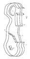
- FIG. 3 shows a finished punch knife with internals, partly in section.
- a plate 3 ' from which the reinforcing plate 3 is to be punched, lies above the knife 1. This plate is pressed against the knife 1 by devices customary in the stamping industry and finally reaches the position shown in FIG. 2.
- the reinforcing plate 3 sits with its punched-out edges in the groove 4 and is held by it.
- the punch knife is thus completed in one operation, but can be further stiffened by connecting the knife to the reinforcing plate. It is necessary to connect the knife ends to one another before punching the reinforcing plate, preferably to weld.
- Fig. 3 is a punch knife according to the invention with some internals, some. in section.
- the internals are two perforated pipes 6 and a series of marking mandrels 5 which form a seam sign line.
- An inner knife 8 is shown in section, whereby its groove is visible in the area of the reinforcing plate 3.
- an opening 7 is further provided in the reinforcing plate 3 through which the weight of the punch knife is reduced and its handling is facilitated. This opening also facilitates the removal of the punched-out material from the knife.
- the method according to the invention can be modified in various ways. It is therefore not necessary for the plate to be pressed in from above, and the reinforcement plate can also have been provided with the internals before the punching, if desired. Especially when using stronger reinforcement plates, it is possible to press against the knife with a pressure device, which is also provided with a cutting edge (opposite the knife edge or offset to the knife edge) in order to facilitate the cutting process.
- the invention also relates to punch knives which have been produced by the method according to the invention.
Landscapes
- Engineering & Computer Science (AREA)
- Mechanical Engineering (AREA)
- Life Sciences & Earth Sciences (AREA)
- Forests & Forestry (AREA)
- Perforating, Stamping-Out Or Severing By Means Other Than Cutting (AREA)
Applications Claiming Priority (2)
| Application Number | Priority Date | Filing Date | Title |
|---|---|---|---|
| AT3354/87 | 1987-12-18 | ||
| AT0335487A AT391292B (de) | 1987-12-18 | 1987-12-18 | Verfahren zur herstellung eines ein- oder zweiseitigen stanzmessers fuer nichtmetallische werkstoffe |
Publications (2)
| Publication Number | Publication Date |
|---|---|
| EP0321437A2 true EP0321437A2 (fr) | 1989-06-21 |
| EP0321437A3 EP0321437A3 (fr) | 1991-06-05 |
Family
ID=3549258
Family Applications (1)
| Application Number | Title | Priority Date | Filing Date |
|---|---|---|---|
| EP19880890286 Ceased EP0321437A3 (fr) | 1987-12-18 | 1988-11-14 | Procédé pour la fabrication d'un outil de découpe à simple ou à double tranchant pour les matériaux non métalliques |
Country Status (5)
| Country | Link |
|---|---|
| US (1) | US4938105A (fr) |
| EP (1) | EP0321437A3 (fr) |
| JP (1) | JPH01193197A (fr) |
| AT (1) | AT391292B (fr) |
| ZA (1) | ZA887324B (fr) |
Cited By (2)
| Publication number | Priority date | Publication date | Assignee | Title |
|---|---|---|---|---|
| FR2705918A1 (fr) * | 1993-06-04 | 1994-12-09 | Hexagone | Kit de marquage par perforations. |
| WO2003066292A1 (fr) * | 2002-02-07 | 2003-08-14 | Peach Office Products Ltd. | Couteau de machine a decouper |
Families Citing this family (6)
| Publication number | Priority date | Publication date | Assignee | Title |
|---|---|---|---|---|
| DE19535598A1 (de) * | 1995-09-25 | 1997-03-27 | Drahtcord Saar Gmbh & Co Kg | Verfahren zur Herstellung eines Stahlcords |
| US7047858B2 (en) * | 1999-12-10 | 2006-05-23 | Rohrer Ag | Chamfer device for cutting packaging materials |
| US7954407B1 (en) * | 2000-05-30 | 2011-06-07 | Jenkins Henry H | Steel rule die and steel rule |
| US20110026856A1 (en) * | 2009-07-29 | 2011-02-03 | Erick Erardo Lopez-Araiza | Bag, Bag Pack, and Methods and Compositions for Making and Dispensing Thereof |
| JP2016174658A (ja) * | 2015-03-19 | 2016-10-06 | エトワール株式会社 | スリッパ甲部材の作製方法及び金型 |
| CN112296618A (zh) * | 2020-09-16 | 2021-02-02 | 南通西土瓦工贸有限公司 | 一种刀模制作工艺 |
Family Cites Families (8)
| Publication number | Priority date | Publication date | Assignee | Title |
|---|---|---|---|---|
| US2167880A (en) * | 1936-05-28 | 1939-08-01 | Progressive Service Company | Method of making dies |
| US2129448A (en) * | 1937-09-18 | 1938-09-06 | Endicott Johnson Corp | Cutting die |
| US2298041A (en) * | 1941-01-28 | 1942-10-06 | Francis J Dedrick | Method of making dies |
| US2853134A (en) * | 1955-07-05 | 1958-09-23 | Progressive Service Company | Manufacture of steel rule dies |
| GB1126613A (en) * | 1965-08-31 | 1968-09-11 | Stafford Tool And Die Company | Improved die for cutting sheet materials |
| CH493313A (de) * | 1968-02-03 | 1970-07-15 | Roeder & Spengler Ohg | Stanzform |
| GB2115735A (en) * | 1982-03-04 | 1983-09-14 | Pa Management Consult | Press knife |
| AT389480B (de) * | 1988-01-22 | 1989-12-11 | Wieser Ludwig Dipl Ing | Verfahren zur herstellung eines stanzwerkzeuges |
-
1987
- 1987-12-18 AT AT0335487A patent/AT391292B/de not_active IP Right Cessation
-
1988
- 1988-09-29 ZA ZA887324A patent/ZA887324B/xx unknown
- 1988-11-14 EP EP19880890286 patent/EP0321437A3/fr not_active Ceased
- 1988-12-15 US US07/285,094 patent/US4938105A/en not_active Expired - Fee Related
- 1988-12-16 JP JP63316606A patent/JPH01193197A/ja active Pending
Cited By (2)
| Publication number | Priority date | Publication date | Assignee | Title |
|---|---|---|---|---|
| FR2705918A1 (fr) * | 1993-06-04 | 1994-12-09 | Hexagone | Kit de marquage par perforations. |
| WO2003066292A1 (fr) * | 2002-02-07 | 2003-08-14 | Peach Office Products Ltd. | Couteau de machine a decouper |
Also Published As
| Publication number | Publication date |
|---|---|
| JPH01193197A (ja) | 1989-08-03 |
| AT391292B (de) | 1990-09-10 |
| ZA887324B (en) | 1989-06-28 |
| US4938105A (en) | 1990-07-03 |
| ATA335487A (de) | 1990-03-15 |
| EP0321437A3 (fr) | 1991-06-05 |
Similar Documents
| Publication | Publication Date | Title |
|---|---|---|
| EP0155619B1 (fr) | Procédé pour réaliser des liaisons de tôles | |
| DE4333052C2 (de) | Selbststanzende Befestigungsvorrichtung | |
| DE2628550A1 (de) | Verfahren zum blindnieten | |
| DE102013217633A1 (de) | Stanzniet und Verfahren zur Befestigung einzelner Bauteile aneinander, von denen mindestens ein Bauteil durch ein Werkstück aus Verbundmaterial gebildet ist | |
| DE2720924A1 (de) | Lappenverbindung zum festen gegenseitigen verbinden von plattenstuecken und verfahren zur herstellung einer solchen lappenverbindung | |
| DE19810367C1 (de) | Verfahren zum Herstellen eines Durchzugs | |
| DE2648637A1 (de) | Verfahren zur befestigung einer mutter an einer stuetzplatte | |
| DE69711696T2 (de) | Verfahren zum quereinpressen eines zylindrischen teils in ein rohrförmiges teil und entsprechende einheit aus zwei teilen | |
| DE69617614T2 (de) | Ein werkzeug zur herstellung von verbindungsstellen zwischen plattenförmigen teilen | |
| AT391292B (de) | Verfahren zur herstellung eines ein- oder zweiseitigen stanzmessers fuer nichtmetallische werkstoffe | |
| EP2456296B1 (fr) | Piquet de vigne | |
| DE102019113560A1 (de) | Selbststanzendes Nietelement, Zusammenbauteil bestehend aus dem Nietelement und einem Bauteil, Verfahren zur Herstellung des Zusammenbauteils und Matrize | |
| DE2163763A1 (de) | Vorrichtung zum verbinden zweier tafeln aus blech | |
| DE3201717A1 (de) | Verfahren zum verbinden von duennwandigen werkstuecken und nach dem verfahren hergestelltes erzeugnis | |
| DE3229246C2 (fr) | ||
| EP1775042B1 (fr) | Procédé et dispositif de poinçonnage d'une tôle | |
| EP3575618B1 (fr) | Élément rivet autoperforant, composant d'assemblage composé de l'élément rivet et d'un composant, procédé de fabrication du composant d'assemblage et matrice | |
| DE3133270A1 (de) | Verfahren und vorrichtung zum herstellen einer platte oder tafel mit durch pressschweissen verbundener mutter | |
| DE2432192C3 (de) | Krampe, und damit hergestelltes zusammengesetztes Erzeugnis | |
| EP4327422B1 (fr) | Composant de chemin de câbles constitué de métal, plus particulièrement chemin de câbles ou couvercle de chemin de câbles | |
| DE3210647C2 (de) | Verfahren zum Kaltpressen aufeinanderliegender Metallblechscheiben | |
| DE2066024C3 (de) | Biegewerkzeug zum Herstellen von Plattengliedern für Plattenbandförderer | |
| DE29707669U1 (de) | Stanzniet | |
| DE19643076C2 (de) | Vorrichtung zum in einem Arbeitsgang erfolgenden Stanzen und Fügen mindestens zweier Blechteile | |
| DE562614C (de) | Zahnrad aus Pressmasse |
Legal Events
| Date | Code | Title | Description |
|---|---|---|---|
| PUAI | Public reference made under article 153(3) epc to a published international application that has entered the european phase |
Free format text: ORIGINAL CODE: 0009012 |
|
| AK | Designated contracting states |
Kind code of ref document: A2 Designated state(s): AT BE CH DE ES FR GB GR IT LI LU NL SE |
|
| PUAL | Search report despatched |
Free format text: ORIGINAL CODE: 0009013 |
|
| AK | Designated contracting states |
Kind code of ref document: A3 Designated state(s): AT BE CH DE ES FR GB GR IT LI LU NL SE |
|
| 17P | Request for examination filed |
Effective date: 19910627 |
|
| 17Q | First examination report despatched |
Effective date: 19911223 |
|
| RAP1 | Party data changed (applicant data changed or rights of an application transferred) |
Owner name: MARTIN MILLER AKTIENGESELLSCHAFT |
|
| STAA | Information on the status of an ep patent application or granted ep patent |
Free format text: STATUS: THE APPLICATION HAS BEEN REFUSED |
|
| 18R | Application refused |
Effective date: 19930204 |