EP0321591A1 - Moule pour la production d'articles en plastiques multicomposants - Google Patents
Moule pour la production d'articles en plastiques multicomposants Download PDFInfo
- Publication number
- EP0321591A1 EP0321591A1 EP87118612A EP87118612A EP0321591A1 EP 0321591 A1 EP0321591 A1 EP 0321591A1 EP 87118612 A EP87118612 A EP 87118612A EP 87118612 A EP87118612 A EP 87118612A EP 0321591 A1 EP0321591 A1 EP 0321591A1
- Authority
- EP
- European Patent Office
- Prior art keywords
- frame
- tool carrier
- shafts
- tool
- tool according
- Prior art date
- Legal status (The legal status is an assumption and is not a legal conclusion. Google has not performed a legal analysis and makes no representation as to the accuracy of the status listed.)
- Granted
Links
Images
Classifications
-
- B—PERFORMING OPERATIONS; TRANSPORTING
- B29—WORKING OF PLASTICS; WORKING OF SUBSTANCES IN A PLASTIC STATE IN GENERAL
- B29C—SHAPING OR JOINING OF PLASTICS; SHAPING OF MATERIAL IN A PLASTIC STATE, NOT OTHERWISE PROVIDED FOR; AFTER-TREATMENT OF THE SHAPED PRODUCTS, e.g. REPAIRING
- B29C33/00—Moulds or cores; Details thereof or accessories therefor
- B29C33/20—Opening, closing or clamping
- B29C33/22—Opening, closing or clamping by rectilinear movement
-
- Y—GENERAL TAGGING OF NEW TECHNOLOGICAL DEVELOPMENTS; GENERAL TAGGING OF CROSS-SECTIONAL TECHNOLOGIES SPANNING OVER SEVERAL SECTIONS OF THE IPC; TECHNICAL SUBJECTS COVERED BY FORMER USPC CROSS-REFERENCE ART COLLECTIONS [XRACs] AND DIGESTS
- Y10—TECHNICAL SUBJECTS COVERED BY FORMER USPC
- Y10S—TECHNICAL SUBJECTS COVERED BY FORMER USPC CROSS-REFERENCE ART COLLECTIONS [XRACs] AND DIGESTS
- Y10S425/00—Plastic article or earthenware shaping or treating: apparatus
- Y10S425/221—Injection mold closing and locking clamp, wedge or retention means
Definitions
- the invention has for its object to develop a mold of the type mentioned in such a way that there is a significant reduction in the weight of moving in the intended use of the mold masses.
- the support elements are designed as a pivot lever, that the pivot levers are fixed to continuous waves and and transverse to their direction extending end faces with the support surfaces are engageable that the waves are stored in the frame on the side facing away from the part tools side of the movable tool carrier.
- the common drive is thereby simplified.
- the pivot levers may be of columnar shape and have in this case, with a low weight on a particularly large load capacity in the direction of their extension.
- the waves are mounted in the plane of movement of the support surfaces in the frame with the tool carrier blocked in the direction of the closing movement, i.e. in the direction of the introduced forces: whereby an optimal utilization of the load capacity is ensured.
- the pivot lever can be made very easy and are therefore easily movable. Your drive does not interfere with the frame. Nevertheless, there is a mutual superposition of the bending stiffness of the shaft with that of the tool carrier, which allows the latter to be very easy to build and in this way to achieve a significant reduction in the inertial masses moved during the normal working cycle. In addition, lateral forces are avoided, which makes it possible to reduce the cost of the guides between the frame and the relatively movable tool carrier and still obtain a high-precision mutual assignment in each assignment position. Also, the wear in the area mentioned is clearly reduced.
- the effect described above is particularly evident when the pivot levers are distributed over the entire length of the movable tool carrier and fixed in a constant small mutual distance to the waves.
- the bending stress of the movable tool carrier in the direction of its longitudinal axis is accordingly low and allows easy design, which can already be achieved by using relatively low driving forces large accelerations during opening and closing of the mold.
- the cycle times are correspondingly low and facilitate the use of the mold in mass production.
- the pivot levers are fixed to pairwise adjacent oppositely rotatable Welllen and can be stored substantially transversely to the direction of the closing movement in the frame.
- the pivot levers of each shaft pair are assigned to each other gap and thus can be stored in interlocking, there is the possibility to increase the length of the pivot lever and thus the length of the lifting movement of the movable tool carrier accordingly.
- the support surfaces are arranged on the side facing away from the part tools side of the movable tool carrier. This can be formed by a rectangular plate, with an arrangement in the region of the longitudinal edges is recommended.
- the length of the pivot lever can be sized accordingly large, which improves the accessibility of the open mold.
- the device transporting the movable tool carrier to a first position is not exposed to the action of the closing forces generated by the lifting device due to the mechanical locking of the tool carrier in the first position.
- a sufficient only the transport of the tool carrier design of the device is therefore sufficient and achievable with easy to install, small-scale facilities.
- Corresponding devices are available at low cost and it makes sense, if necessary, to attack a larger number of the same effect on a large number of load application points and thus to allow easy training of the tool carrier and thereby reduce its weight in terms of improved mobility.
- the tool carrier of the relatively movable unit with its support surfaces is static ru stored and supported on the pivot levers, which usually does not result in uneven wear in the area of the contacting surfaces. Even after long-term use, a precise mutual association of the two sub-tools in the first position is always ensured in the mold according to the invention.
- the relatively movable tool carrier is supported by a plurality of support surfaces on the pivot levers. This also results in several force introduction points, which makes it possible to make the tool carrier as a function of the number and the mutual Zuornung the same light and thus easy to move without a deterioration of the stiffness would have to be accepted. With regard to the design of the associated movement device that is of considerable advantage.
- the Malawi- and the lower tool part still have a small mutual distance.
- the further mutual approach of the two sub-tools and their subsequent compression are effected in the mold according to the invention exclusively by the lifting device. This has only a very small stroke and is not significantly burdened by management tasks. A very sensitive approach and compression of Malawiober- and the lower tool part is possible.
- the mobility of the tool carrier is determined depending on the desired accessibility of the mold. It is insofar readily possible to store both tool carrier or only the upper or only the lower tool carrier movable. However, under certain technical and economic aspects, the last-mentioned embodiment is usually given preference in the context of the present invention. It also facilitates the feeding of the reaction mixture in the closed mold.
- both tool carriers are moved on rectilinear tracks in the closed position. Pivoting movements of at least one of the two tool carriers are rather also possible and have proven particularly for the upper tool carrier, because this results in the possibility to make the space above the lower tool part and bring the upper part of the tool in a likewise freely accessible from above position. Both tool parts can be easily changed by means of a crane.
- the two tool carriers consist of rigid plates, which are arranged in a frame.
- the latter is expedient designed like a frame and gives the Gesmtkonstrutation a great robustness.
- the lifting device executes a small stroke, which also allows the use of sealless, pressurized lifting elements with the considerations to include.
- Lifting elements of this type usually have a pillow-like shape. They can consist of a flexible film material and are connected by an inlet / outlet valve with a pressure medium source.
- Corresponding lifting elements can be formed by fabric-reinforced hoses, as used for example in the fire department. They are characterized by a particularly high mechanical resistance with good flexibility, resulting in a nearly linear dependence between the generated closing force and the internal pressure of the hose. A sensitive application of the two parts of the mold is thereby promoted. Corresponding hoses are preferably arranged in the region of the longitudinal sides of the tools in the case of elongate tools.
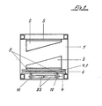
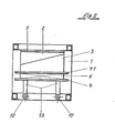
- the reproduced in the drawing mold comprises a frame 1, which is datagestzt from frame-like welded steel profiles of large cross-section.
- the frame is accordingly of great capacity and stiffness and allows the immediate lashing of all necessary for normal operation auxiliary and auxiliary equipment and thus the production of the operational readiness of the mold at a separate location from the later site.
- the time required for a tool change times of business interruption at the site can be reduced to a minimum, and it is cognitive detox to the ready unit during transport by the unit enclosing the outside, frame-like frame 1 are largely excluded. A change of the complete unit is therefore usually difficult.
- the frame-like frame 1 consists of the upper and the lower frame, which are arranged one above the other in a matching, rectangular plan and rigidly connected at the vertices by columns, not shown.
- the movable tool carrier 4 rests with the mold open on the upper side of the lower frame. He is additionally supported by a lifting device, not shown, which allows lifting in the direction of the upper frame. In order to prevent lateral migration of the tool carrier 4, it is provided with guides, not shown, which enclose in the vertical direction réelleckende guide rails of the columns like a clip.
- the lifting device is used only for lifting the lower tool carrier 4 in the first position. It may comprise, for example, motor-operated rack or spindle drives which connect the movable tool carrier 4 and the frame 1 in the region of the columns.
- the stroke of the lifting device is expedient slightly larger than required for reaching the first position, to promote the trouble-free Einrükken of the pivot lever 9.3 comprehensive Blokkier wisdom.
- the blocking device is then actuated, which can be done for example by a stepper, and the lower tool holder 4 then stored to relieve the lifting device with its support surfaces 8 on the pivoting levers 9.3.
- the lower tool carrier 4 is thus in the first position. Also, the subsequent steps can be controlled automatically by the stepper.
- the pivot lever 9.3 are pivotally mounted in the subframe of the frame.
- the pivoting is effected by two motor-driven shafts 10, at which the pivot lever 9.3 are fixed at equal intervals.
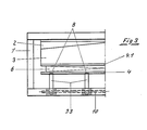
- a lifting device 6 is arranged only on the lower tool carrier 4.
- This consists of a lifting element in the form of a pressurizable air cushion, which engages under the subcarrier 4.1 with the size of the tool corresponding pneumatic action surface.
- the in the first position still a small distance from the upper tool part 2 having the lower tool part 3 can thereby be applied sensitively to the tool upper part 3 with the supply of compressed air and evenly pressed with the same. This is a considerable advantage for the protection of the tool and the production of high quality molded parts.
- the mold is opened again, including in the first step emptied the air cushion and thereby the subcarrier 4.1 is placed on the lower, movable tool carrier 4 for filing.
- the movable tool carrier 4 is then raised slightly to relieve the pivot lever and can disengage. It can then be returned from the position shown in Figure 2 in the position shown in Figure 1.
- the finished molded part is thus removable and the open mold to prepare for the next molding process veyoggbar.
- the pivot levers are operated by a common drive, and from this point of view, it has proven to be constructive in terms of making them uniform in their entirety.
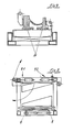
- FIG. 4 shows a cross-section of a tool lower part, in which the lifting device is formed by two mutually parallel, elongated air cushion. These are formed by fabric-reinforced fire hoses, which are arranged in a series connection below the longitudinal sides of the elongated molding tool. They have at negligible elongation excellent flexibility, resulting in a linear dependence between the internal pressure and the radial expansion of the diameter when feeding a flowable medium.
- the stroke and the closing force can thereby be controlled sensitively, it being of significant importance that any deformations of the tool holder and / or the tools are automatically compensated. Even if corresponding deformations are present, therefore, a closing movement of the molding tool which is completed in all subregions is ensured, which simplifies the sealing thereof. Unwanted transverse displacements of the lower mold part are prevented by the guides shown.
- Figure 5 shows a mold similar to Figure 1, in which the space above the mold base can be made free to allow replacement of the tool base by means of a crane.
- both the upper frame of the frame and the upper tool carrier are pivotally mounted in the manner shown. A replacement of the upper tool mit.Hilfe a crane is also possible.
- the pivoting of the upper frame and the upper tool carrier is effected by piston-i-cylinder units, not shown.
- Other piston / cylinder units are used for the mechanical blocking of the upper frame or upper tool carrier in the position shown. They cooperate with a latch closure 9.1 or a hook closure 9.2.
Landscapes
- Engineering & Computer Science (AREA)
- Mechanical Engineering (AREA)
- Moulds For Moulding Plastics Or The Like (AREA)
- Details Of Garments (AREA)
Priority Applications (6)
| Application Number | Priority Date | Filing Date | Title |
|---|---|---|---|
| DE19863620371 DE3620371A1 (de) | 1986-06-18 | 1986-06-18 | Formwerkzeug |
| EP87118612A EP0321591B1 (fr) | 1987-12-15 | 1987-12-15 | Moule pour la production d'articles en plastiques multicomposants |
| AT87118612T ATE54602T1 (de) | 1987-12-15 | 1987-12-15 | Formwerkzeug zur herstellung eines formteiles aus mehrkomponentenkunststoff. |
| DE8787118612T DE3763847D1 (de) | 1987-12-15 | 1987-12-15 | Formwerkzeug zur herstellung eines formteiles aus mehrkomponentenkunststoff. |
| ES87118612T ES2016328B3 (es) | 1987-12-15 | 1987-12-15 | Herramienta de forma para la fabricacion de una pieza de forma de material sintetico de componentes multiples |
| US07/275,742 US4900243A (en) | 1987-12-15 | 1988-11-21 | Molding apparatus |
Applications Claiming Priority (1)
| Application Number | Priority Date | Filing Date | Title |
|---|---|---|---|
| EP87118612A EP0321591B1 (fr) | 1987-12-15 | 1987-12-15 | Moule pour la production d'articles en plastiques multicomposants |
Publications (2)
| Publication Number | Publication Date |
|---|---|
| EP0321591A1 true EP0321591A1 (fr) | 1989-06-28 |
| EP0321591B1 EP0321591B1 (fr) | 1990-07-18 |
Family
ID=8197518
Family Applications (1)
| Application Number | Title | Priority Date | Filing Date |
|---|---|---|---|
| EP87118612A Expired - Lifetime EP0321591B1 (fr) | 1986-06-18 | 1987-12-15 | Moule pour la production d'articles en plastiques multicomposants |
Country Status (5)
| Country | Link |
|---|---|
| US (1) | US4900243A (fr) |
| EP (1) | EP0321591B1 (fr) |
| AT (1) | ATE54602T1 (fr) |
| DE (1) | DE3763847D1 (fr) |
| ES (1) | ES2016328B3 (fr) |
Cited By (1)
| Publication number | Priority date | Publication date | Assignee | Title |
|---|---|---|---|---|
| EP1857249A2 (fr) | 2006-05-15 | 2007-11-21 | FRIMO Group GmbH | Dispositif de fabrication de pièces en mousse moulées |
Citations (7)
| Publication number | Priority date | Publication date | Assignee | Title |
|---|---|---|---|---|
| FR1543009A (fr) * | 1900-01-01 | Dispositif de verrouillage sur les presses à injecter | ||
| CH377094A (de) * | 1959-06-06 | 1964-04-30 | Krauss Maffei Ag | Formschliessvorrichtung, insbesondere für thermoplastische Kunststoffe verarbeitende Spritzgussmaschinen |
| GB1032477A (en) * | 1963-09-17 | 1966-06-08 | Eizo Aoki | A hydraulically actuated clamping mechanism for the mold in an injection molding apparatus |
| US3862596A (en) * | 1973-08-22 | 1975-01-28 | Ladislao Wladyslaw Putkowski | Press with adjustable platen latching mechanism |
| GB2005186A (en) * | 1977-06-17 | 1979-04-19 | Micro & Precision Mouldings Lt | Mould closing, clamping and opening means |
| GB2031787A (en) * | 1978-10-18 | 1980-04-30 | Hull Corp | Platen type moulding press |
| US4461456A (en) * | 1983-05-26 | 1984-07-24 | Munna Rocco M | Hydraulic leveler ramp |
Family Cites Families (5)
| Publication number | Priority date | Publication date | Assignee | Title |
|---|---|---|---|---|
| US2335807A (en) * | 1942-05-19 | 1943-11-30 | Aluminum Co Of America | Mold locking mechanism |
| US3816044A (en) * | 1973-02-07 | 1974-06-11 | Foldcraft Co | Automatic press |
| SE435602B (sv) * | 1983-04-19 | 1984-10-08 | Cold Isostatic Press Syst Kb | Isostatisk press |
| JPS60132708A (ja) * | 1983-12-21 | 1985-07-15 | Nissei Plastics Ind Co | 成形機の型締装置 |
| CA1250781A (fr) * | 1985-11-12 | 1989-03-07 | Hepburn (John T.) Limited | Presse hydraulique |
-
1987
- 1987-12-15 ES ES87118612T patent/ES2016328B3/es not_active Expired - Lifetime
- 1987-12-15 EP EP87118612A patent/EP0321591B1/fr not_active Expired - Lifetime
- 1987-12-15 AT AT87118612T patent/ATE54602T1/de not_active IP Right Cessation
- 1987-12-15 DE DE8787118612T patent/DE3763847D1/de not_active Expired - Lifetime
-
1988
- 1988-11-21 US US07/275,742 patent/US4900243A/en not_active Expired - Fee Related
Patent Citations (7)
| Publication number | Priority date | Publication date | Assignee | Title |
|---|---|---|---|---|
| FR1543009A (fr) * | 1900-01-01 | Dispositif de verrouillage sur les presses à injecter | ||
| CH377094A (de) * | 1959-06-06 | 1964-04-30 | Krauss Maffei Ag | Formschliessvorrichtung, insbesondere für thermoplastische Kunststoffe verarbeitende Spritzgussmaschinen |
| GB1032477A (en) * | 1963-09-17 | 1966-06-08 | Eizo Aoki | A hydraulically actuated clamping mechanism for the mold in an injection molding apparatus |
| US3862596A (en) * | 1973-08-22 | 1975-01-28 | Ladislao Wladyslaw Putkowski | Press with adjustable platen latching mechanism |
| GB2005186A (en) * | 1977-06-17 | 1979-04-19 | Micro & Precision Mouldings Lt | Mould closing, clamping and opening means |
| GB2031787A (en) * | 1978-10-18 | 1980-04-30 | Hull Corp | Platen type moulding press |
| US4461456A (en) * | 1983-05-26 | 1984-07-24 | Munna Rocco M | Hydraulic leveler ramp |
Cited By (2)
| Publication number | Priority date | Publication date | Assignee | Title |
|---|---|---|---|---|
| EP1857249A2 (fr) | 2006-05-15 | 2007-11-21 | FRIMO Group GmbH | Dispositif de fabrication de pièces en mousse moulées |
| DE102006022546B4 (de) * | 2006-05-15 | 2011-05-26 | Frimo Group Gmbh | Vorrichtung zur Herstellung von Schaumformteilen |
Also Published As
| Publication number | Publication date |
|---|---|
| EP0321591B1 (fr) | 1990-07-18 |
| ATE54602T1 (de) | 1990-08-15 |
| US4900243A (en) | 1990-02-13 |
| DE3763847D1 (de) | 1990-08-23 |
| ES2016328B3 (es) | 1990-11-01 |
Similar Documents
| Publication | Publication Date | Title |
|---|---|---|
| DE164062T1 (de) | Vorrichtung zum wechseln einer form in einer presse, insbesondere in einer spritzgiessmaschine. | |
| DE69309312T2 (de) | Verfahren und vorrichtung zum wechseln von formen in warmformpressen | |
| DE2932698C2 (de) | Vorrichtung zum Zusammenlegen von Trägermatten und Metallfolienbahnabschnitten im Zuge der Herstellung von Laminatplatten | |
| DE4010024A1 (de) | Fertigungsanlage mit parallel- und nebenfoerderwegen | |
| DE2717768B2 (de) | Wechseleinrichtung für die Batterien eines Elektrofahrzeuge | |
| DE2810789B2 (de) | Vorrichtung zur Herstellung von Formkörpern aus schäumbarem Kunststoff | |
| DE2456840C3 (de) | Behältnis zur Lagerung, Führung und UmschnUruflg eines nicht stabilen Stapels aus waagrecht liegenden, blattartigem Material | |
| DE68903063T2 (de) | Maschine zum kontinuierlichen verpacken von produkten, insbesondere von nahrungsmitteln oder pharmazeutischen produkten, in kunststoffbehaeltern. | |
| DE1177058B (de) | Anlage zum Herstellen von Bauelementen od. dgl. Gegenstaenden aus Zellenbeton | |
| DE3513136C1 (de) | Kontinuierlich arbeitende Presse fuer die Herstellung von Laminaten | |
| DE4311154C2 (de) | Einrichtung zur Endbearbeitung eines in einer Tuschierpresse tuschierten Werkzeuges | |
| DE2411300B1 (de) | Einrichtung zum Zusammenlegen einer unteren Decklage, einer Mittellage und einer oberen Decklage zu einem Stapel im Zuge der Herstellung von vergüteten Trägerplatten und dgl | |
| DE2246190B2 (de) | Flurförderzeug zum Auswechseln von Modellplattenpaare einer Gießerei-Formanlage | |
| EP0321591B1 (fr) | Moule pour la production d'articles en plastiques multicomposants | |
| DE2316860C3 (de) | Verfahren zum Herstellen von dreidimensional verstärkten Isolationsblöcken | |
| DE2844565B2 (de) | Einrichtung zur Herstellung von Gießereiformen mit einer Modelleinrichtung | |
| DE3620371C2 (fr) | ||
| DE3047650C2 (de) | Vorrichtung zum Herstellen von Betonplatten | |
| DE3529775A1 (de) | Vorrichtung zur herstellung von formteilen | |
| DE2452509A1 (de) | Foerderer | |
| DE3108337A1 (de) | Strangpressmaschine und verfahren zum betrieb einer strangpressmaschine | |
| DE3201447C1 (de) | Vorrichtung zum Wechseln von Modellplatten in Formmaschinen | |
| DE1941186B2 (de) | Rollenwechsler für Rollenrichtmaschinen | |
| DE2921157C2 (de) | Vorrichtung zur Verformung von geschäumten Platten oder dergl. aus Kunststoffen | |
| DE1938254C3 (de) | Einrichtung zum Vulkanisieren von Fördergurten und ähnlichen bandförmigen Gegenständen |
Legal Events
| Date | Code | Title | Description |
|---|---|---|---|
| PUAI | Public reference made under article 153(3) epc to a published international application that has entered the european phase |
Free format text: ORIGINAL CODE: 0009012 |
|
| 17P | Request for examination filed |
Effective date: 19890321 |
|
| AK | Designated contracting states |
Kind code of ref document: A1 Designated state(s): AT BE DE ES FR GB IT NL SE |
|
| 17Q | First examination report despatched |
Effective date: 19891030 |
|
| ITF | It: translation for a ep patent filed | ||
| GRAA | (expected) grant |
Free format text: ORIGINAL CODE: 0009210 |
|
| AK | Designated contracting states |
Kind code of ref document: B1 Designated state(s): AT BE DE ES FR GB IT NL SE |
|
| REF | Corresponds to: |
Ref document number: 54602 Country of ref document: AT Date of ref document: 19900815 Kind code of ref document: T |
|
| REF | Corresponds to: |
Ref document number: 3763847 Country of ref document: DE Date of ref document: 19900823 |
|
| ET | Fr: translation filed | ||
| GBT | Gb: translation of ep patent filed (gb section 77(6)(a)/1977) | ||
| PLBE | No opposition filed within time limit |
Free format text: ORIGINAL CODE: 0009261 |
|
| STAA | Information on the status of an ep patent application or granted ep patent |
Free format text: STATUS: NO OPPOSITION FILED WITHIN TIME LIMIT |
|
| 26N | No opposition filed | ||
| ITTA | It: last paid annual fee | ||
| EAL | Se: european patent in force in sweden |
Ref document number: 87118612.8 |
|
| PGFP | Annual fee paid to national office [announced via postgrant information from national office to epo] |
Ref country code: GB Payment date: 20001127 Year of fee payment: 14 |
|
| PGFP | Annual fee paid to national office [announced via postgrant information from national office to epo] |
Ref country code: ES Payment date: 20001214 Year of fee payment: 14 |
|
| PGFP | Annual fee paid to national office [announced via postgrant information from national office to epo] |
Ref country code: FR Payment date: 20001219 Year of fee payment: 14 |
|
| PGFP | Annual fee paid to national office [announced via postgrant information from national office to epo] |
Ref country code: NL Payment date: 20001221 Year of fee payment: 14 |
|
| PGFP | Annual fee paid to national office [announced via postgrant information from national office to epo] |
Ref country code: BE Payment date: 20001222 Year of fee payment: 14 Ref country code: AT Payment date: 20001222 Year of fee payment: 14 |
|
| PGFP | Annual fee paid to national office [announced via postgrant information from national office to epo] |
Ref country code: SE Payment date: 20001228 Year of fee payment: 14 |
|
| PG25 | Lapsed in a contracting state [announced via postgrant information from national office to epo] |
Ref country code: GB Free format text: LAPSE BECAUSE OF NON-PAYMENT OF DUE FEES Effective date: 20011215 Ref country code: AT Free format text: LAPSE BECAUSE OF NON-PAYMENT OF DUE FEES Effective date: 20011215 |
|
| PG25 | Lapsed in a contracting state [announced via postgrant information from national office to epo] |
Ref country code: SE Free format text: LAPSE BECAUSE OF NON-PAYMENT OF DUE FEES Effective date: 20011216 |
|
| PG25 | Lapsed in a contracting state [announced via postgrant information from national office to epo] |
Ref country code: BE Free format text: LAPSE BECAUSE OF NON-PAYMENT OF DUE FEES Effective date: 20011231 |
|
| REG | Reference to a national code |
Ref country code: GB Ref legal event code: IF02 |
|
| BERE | Be: lapsed |
Owner name: FRITSCHE-MOLLMANN G.M.B.H. & CO. K.G. Effective date: 20011231 |
|
| PG25 | Lapsed in a contracting state [announced via postgrant information from national office to epo] |
Ref country code: NL Free format text: LAPSE BECAUSE OF NON-PAYMENT OF DUE FEES Effective date: 20020701 |
|
| EUG | Se: european patent has lapsed |
Ref document number: 87118612.8 |
|
| GBPC | Gb: european patent ceased through non-payment of renewal fee |
Effective date: 20011215 |
|
| PG25 | Lapsed in a contracting state [announced via postgrant information from national office to epo] |
Ref country code: FR Free format text: LAPSE BECAUSE OF NON-PAYMENT OF DUE FEES Effective date: 20020830 |
|
| NLV4 | Nl: lapsed or anulled due to non-payment of the annual fee |
Effective date: 20020701 |
|
| REG | Reference to a national code |
Ref country code: FR Ref legal event code: ST |
|
| PG25 | Lapsed in a contracting state [announced via postgrant information from national office to epo] |
Ref country code: ES Free format text: LAPSE BECAUSE OF NON-PAYMENT OF DUE FEES Effective date: 20021216 |
|
| PGFP | Annual fee paid to national office [announced via postgrant information from national office to epo] |
Ref country code: DE Payment date: 20021219 Year of fee payment: 16 |
|
| REG | Reference to a national code |
Ref country code: ES Ref legal event code: FD2A Effective date: 20030113 |
|
| PG25 | Lapsed in a contracting state [announced via postgrant information from national office to epo] |
Ref country code: DE Free format text: LAPSE BECAUSE OF NON-PAYMENT OF DUE FEES Effective date: 20040701 |
|
| PG25 | Lapsed in a contracting state [announced via postgrant information from national office to epo] |
Ref country code: IT Free format text: LAPSE BECAUSE OF NON-PAYMENT OF DUE FEES;WARNING: LAPSES OF ITALIAN PATENTS WITH EFFECTIVE DATE BEFORE 2007 MAY HAVE OCCURRED AT ANY TIME BEFORE 2007. THE CORRECT EFFECTIVE DATE MAY BE DIFFERENT FROM THE ONE RECORDED. Effective date: 20051215 |