EP1857249A2 - Dispositif de fabrication de pièces en mousse moulées - Google Patents
Dispositif de fabrication de pièces en mousse moulées Download PDFInfo
- Publication number
- EP1857249A2 EP1857249A2 EP07009571A EP07009571A EP1857249A2 EP 1857249 A2 EP1857249 A2 EP 1857249A2 EP 07009571 A EP07009571 A EP 07009571A EP 07009571 A EP07009571 A EP 07009571A EP 1857249 A2 EP1857249 A2 EP 1857249A2
- Authority
- EP
- European Patent Office
- Prior art keywords
- machine stand
- central drive
- tool table
- wheels
- guides
- Prior art date
- Legal status (The legal status is an assumption and is not a legal conclusion. Google has not performed a legal analysis and makes no representation as to the accuracy of the status listed.)
- Granted
Links
- 238000004519 manufacturing process Methods 0.000 title claims description 7
- 239000006260 foam Substances 0.000 title description 2
- 230000008878 coupling Effects 0.000 claims abstract description 11
- 238000010168 coupling process Methods 0.000 claims abstract description 11
- 238000005859 coupling reaction Methods 0.000 claims abstract description 11
- 238000010097 foam moulding Methods 0.000 claims description 6
- 230000004075 alteration Effects 0.000 abstract 1
- 230000001360 synchronised effect Effects 0.000 description 4
- 229910000831 Steel Inorganic materials 0.000 description 3
- 239000010959 steel Substances 0.000 description 3
- 230000006378 damage Effects 0.000 description 2
- 238000005187 foaming Methods 0.000 description 2
- 238000000034 method Methods 0.000 description 2
- 238000010276 construction Methods 0.000 description 1
- 230000001419 dependent effect Effects 0.000 description 1
- 238000006073 displacement reaction Methods 0.000 description 1
- 230000000694 effects Effects 0.000 description 1
- 239000004744 fabric Substances 0.000 description 1
- 238000000465 moulding Methods 0.000 description 1
- 238000005096 rolling process Methods 0.000 description 1
Images


Classifications
-
- B—PERFORMING OPERATIONS; TRANSPORTING
- B29—WORKING OF PLASTICS; WORKING OF SUBSTANCES IN A PLASTIC STATE IN GENERAL
- B29C—SHAPING OR JOINING OF PLASTICS; SHAPING OF MATERIAL IN A PLASTIC STATE, NOT OTHERWISE PROVIDED FOR; AFTER-TREATMENT OF THE SHAPED PRODUCTS, e.g. REPAIRING
- B29C44/00—Shaping by internal pressure generated in the material, e.g. swelling or foaming ; Producing porous or cellular expanded plastics articles
- B29C44/34—Auxiliary operations
- B29C44/36—Feeding the material to be shaped
- B29C44/38—Feeding the material to be shaped into a closed space, i.e. to make articles of definite length
- B29C44/42—Feeding the material to be shaped into a closed space, i.e. to make articles of definite length using pressure difference, e.g. by injection or by vacuum
- B29C44/428—Mould constructions; Mould supporting equipment
-
- B—PERFORMING OPERATIONS; TRANSPORTING
- B29—WORKING OF PLASTICS; WORKING OF SUBSTANCES IN A PLASTIC STATE IN GENERAL
- B29C—SHAPING OR JOINING OF PLASTICS; SHAPING OF MATERIAL IN A PLASTIC STATE, NOT OTHERWISE PROVIDED FOR; AFTER-TREATMENT OF THE SHAPED PRODUCTS, e.g. REPAIRING
- B29C33/00—Moulds or cores; Details thereof or accessories therefor
- B29C33/20—Opening, closing or clamping
- B29C33/26—Opening, closing or clamping by pivotal movement
Definitions
- the invention relates to a device for the production of foam moldings, comprising a machine stand and two superimposed arranged therein, variable-length tool tables.
- Such a device is from the EP 0321 591 A1 known.
- the lower tool table can be raised in the direction of the upper tool table in order to bring the tools arranged during the intended use on the two tool tables for the purpose of producing foam mold parts into engagement with one another.
- the known device is very difficult to build and difficult to change.
- the invention is based on the object to further develop such a device so that it is more convenient to use and easier to convert and manufacture.
- the inventive device for the production of foam moldings comprises a machine stand and two superimposed arranged therein, variable-displacement tool tables, of which the upper tool table slidably guided in two opposing slide guides of the machine stand, connected by connecting rods with the ends of pivot levers of a central drive and is displaceable by the pivot lever ,
- the link guides are arranged on the two opposite longitudinal sides of the machine stand and hinder the accessibility of the open tool in any way. It is important to emphasize that the upper tool table always moves synchronously by using a central drive at both ends.
- the mutual slide guides are formed by two vertically spaced scenes of the upper tool table, which are guided by mutually parallel recesses, such as grooves, or projections of the machine stand, for example, ribs. she can even be formed by a sliding body adapted to the slide guides shape and size and optionally be supported by rolling bodies therein or on.
- the scenes on the longest, T - shaped downwardly projecting projections of the upper tool table are set to achieve the best possible guidance of the upper tool table in the machine frame. Accordingly, the arcuate portion of the slide guide must extend to the rear by a correspondingly large amount, so that both scenes are retractable at the same time.
- the arcuate portions may extend parallel to the imaginary paths on which the ends of the pivot levers move, at which the Connecting rods are fixed. This makes it possible to move the upper table with a correspondingly large length of the slotted guides even in an overhead position and to make it particularly easy to load.
- the two pivot levers can be fixed to drive wheels, which are connected by drive chains or timing belt with output gears of the central drive.
- Such a construction is particularly easy to manufacture, very robust and lightweight.
- the output gears can be connected by a coupling shaft of the central drive non-rotatably. This ensures a particularly synchronous movement of the two ends of the upper tool table.
- the coupling shaft is arranged on the back of the machine stand, where it does not affect the accessibility of the tools.
- the coupling shaft can be rotated by at least one electric motor.
- two electric motors in particular electric synchronous motors, present and assigned to the output wheels.
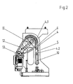
- the device shown in the drawing is used to produce foam moldings, e.g. arrive at the equipment of the interior of motor vehicles to the application. It comprises a machine frame 1 and two superimposed, spaced variable tool tables 2, 3.
- the machine frame consists essentially of two transversely connected, flat steel plates 1.1 which are arranged parallel to each other and pivotally connected to the front with a base 1.2.
- the connecting joint 1.3 is attached to the front end of the machine stand.
- the upper tool table 3 is guided displaceably in two opposing slide guides 4 of the machine stand 1, connected by connecting rods 5 with the ends of pivot levers 6 of a central drive 7 and slidable by the pivot lever 6 in the slide guides 4.
- the length of the connecting rods 5 is dimensioned and matched with the length of the slotted guides 4 and the pivot lever 6 that results in a nearly stretched assignment of the pivot lever 6 to the connecting rods 5, when the upper tool table 3 is in the lowest position.
- the lower end of the slotted guides 4 is not touched by the lower link 4.2, with the result that the upper tool carried by the upper tool table 3 is pressed firmly and tightly against the lower tool table 2 carried by the lower tool. If the pivot lever 6 and the connecting rods 5 are in the range of a straight line, the imaginary extension at the same time cuts through the center of the drive wheels 11, then it is often not necessary to provide besondnere auxiliary equipment for the locking of the tool.
- the mutual slide guides 4 are formed by two vertically spaced scenes 4.1, 4.2 of the upper tool table 3, which are guided by mutually parallel recesses 8 of the machine stand 1.
- the recesses are formed by perforations of the steel plates 1.1. They can also be formed by grooves or ribs.
- the slotted guides 4 are in the manner of an inverted J at the upper end 9 in the steel plates 1.1. arcuately formed swinging back and formed while avoiding sudden changes in direction at the lower end 10 vertically in the direction of the lower tool table 2 extending.
- the arcuately foundedschwingende portion of the slotted guides 4 is dimensioned so that both vertically spaced scenes 4.1, 4.2 at the same time are retractable therein to transfer the upper tool table in a tipped backwards position, as shown in Fig. 3.
- the underside of the upper tool table thus experiences improved accessibility.
- the two pivot levers 6 are fixed to drive wheels 11 which are connected by drive chains 12 or timing belt with output gears 13 of the central drive 7, wherein the diameter ratio of the drive wheels 11 and the output gears 13 is four to one.
- the resulting translation makes it possible to transfer the upper tool table 3 using conventional geared motors 15 quickly and at the same time avoiding disturbing vibrations in the various positions.
- the driven wheels 11 are connected by a coupling shaft 14 of the central drive 7, Fig. 6, non-rotatably. This ensures that the two ends of the upper tool table 3 completely synchronous and tilt-safe in the be transferred to different positions.
- the use of synchronous electric drives in the geared motors underlines this effect and helps to relieve the slide guides 4.
- the coupling shaft 14 is arranged on the back of the machine stand 1, Fig. 6, and thereby not hinder the operation of the device.
- the coupling shaft 14 is basically rotatable by only one electric motor 15.
- a design is used, in which two geared motors are used, which are arranged at the ends of the coupling shaft 14.
- the electric motors 15 are also connected to the drive shafts of the driven wheels 13.
- the machine stand is again in the vertical position according to FIG. 1, which favors the foaming process and prevents injuries of the operating personnel through device components projecting into the working space.
- the upper tool table 3 is reproduced in a view from the side. It consists of a tool holder 3.1, to which the upper tool used can be fixed and two laterally attached thereto, vertically projecting columns 3.2, where the scenes 4.1. and 4.2 of the slotted guide 5 are fixed. They consist in the embodiment shown of roles and have a distance A from each other, which is at least 06 times, preferably 0.8 times, as large as the depth B of the tool table.
- the slotted guide is dimensioned so deep in the curved towards the rear, upper section that the two scenes 4.1 and 4.2 can be accommodated therein simultaneously, as shown in Fig. 3.
- the upper tool table 3 is located in the position shown in Fig. 3, tilted backwards position.
- the distance C between the upper link 4.1 and the tool holder is 0.2 to 0.8 of the distance A in order to obtain a sufficiently large space for the loading of the opened tool.
Landscapes
- Engineering & Computer Science (AREA)
- Mechanical Engineering (AREA)
- Casting Or Compression Moulding Of Plastics Or The Like (AREA)
- Moulds For Moulding Plastics Or The Like (AREA)
- Manufacture Of Porous Articles, And Recovery And Treatment Of Waste Products (AREA)
Applications Claiming Priority (1)
| Application Number | Priority Date | Filing Date | Title |
|---|---|---|---|
| DE102006022546A DE102006022546B4 (de) | 2006-05-15 | 2006-05-15 | Vorrichtung zur Herstellung von Schaumformteilen |
Publications (3)
| Publication Number | Publication Date |
|---|---|
| EP1857249A2 true EP1857249A2 (fr) | 2007-11-21 |
| EP1857249A3 EP1857249A3 (fr) | 2008-05-28 |
| EP1857249B1 EP1857249B1 (fr) | 2010-02-10 |
Family
ID=38353039
Family Applications (1)
| Application Number | Title | Priority Date | Filing Date |
|---|---|---|---|
| EP07009571A Not-in-force EP1857249B1 (fr) | 2006-05-15 | 2007-05-12 | Dispositif de fabrication de pièces en mousse moulées |
Country Status (3)
| Country | Link |
|---|---|
| EP (1) | EP1857249B1 (fr) |
| AT (1) | ATE457220T1 (fr) |
| DE (2) | DE102006022546B4 (fr) |
Cited By (4)
| Publication number | Priority date | Publication date | Assignee | Title |
|---|---|---|---|---|
| CN102133786A (zh) * | 2011-01-27 | 2011-07-27 | 滁州市博精模具设备制造有限公司 | 冰箱箱体发泡模具的涨缩机构 |
| CN104944072A (zh) * | 2015-05-19 | 2015-09-30 | 汪和富 | 一种冰箱发泡自动生产线辅助装置 |
| CN105711025A (zh) * | 2016-03-24 | 2016-06-29 | 安徽信盟机电装备制造有限公司 | 一种伺服电机驱动的汽车天窗电动发泡模架 |
| CN109366845A (zh) * | 2018-12-14 | 2019-02-22 | 吕谨慎 | Eva双色发泡成型机及其中模平移装置 |
Families Citing this family (1)
| Publication number | Priority date | Publication date | Assignee | Title |
|---|---|---|---|---|
| EP2110220A3 (fr) | 2008-04-14 | 2010-08-04 | Fill Gesellschaft m.b.H. | Dispositif de fabrication d'éléments de formage, notamment d'éléments de formage en mousse |
Citations (3)
| Publication number | Priority date | Publication date | Assignee | Title |
|---|---|---|---|---|
| EP0321591A1 (fr) | 1987-12-15 | 1989-06-28 | Fritsche-Möllmann GmbH & Co. KG | Moule pour la production d'articles en plastiques multicomposants |
| DE19723621A1 (de) | 1996-06-06 | 1997-12-11 | Kobe Steel Ltd | Reifenpresse |
| DE20213687U1 (de) | 2002-09-05 | 2003-01-02 | Erlenbach GmbH, 56355 Lautert | Formteilautomat mit schwenkbarer Formhälfte |
Family Cites Families (3)
| Publication number | Priority date | Publication date | Assignee | Title |
|---|---|---|---|---|
| GB1283972A (en) * | 1969-06-25 | 1972-08-02 | Antony Harry Croucher | Improvements in or relating to conveyors |
| GB1374461A (en) * | 1971-06-18 | 1974-11-20 | Precision Eng Worcester Ltd | Split moulds and carriers therefor |
| DE10152392C1 (de) * | 2001-10-24 | 2003-04-24 | Krauss Maffei Kunststofftech | Schließeinheit für eine Kunststoffformmaschine |
-
2006
- 2006-05-15 DE DE102006022546A patent/DE102006022546B4/de not_active Expired - Fee Related
-
2007
- 2007-05-12 EP EP07009571A patent/EP1857249B1/fr not_active Not-in-force
- 2007-05-12 AT AT07009571T patent/ATE457220T1/de active
- 2007-05-12 DE DE502007002794T patent/DE502007002794D1/de active Active
Patent Citations (3)
| Publication number | Priority date | Publication date | Assignee | Title |
|---|---|---|---|---|
| EP0321591A1 (fr) | 1987-12-15 | 1989-06-28 | Fritsche-Möllmann GmbH & Co. KG | Moule pour la production d'articles en plastiques multicomposants |
| DE19723621A1 (de) | 1996-06-06 | 1997-12-11 | Kobe Steel Ltd | Reifenpresse |
| DE20213687U1 (de) | 2002-09-05 | 2003-01-02 | Erlenbach GmbH, 56355 Lautert | Formteilautomat mit schwenkbarer Formhälfte |
Cited By (4)
| Publication number | Priority date | Publication date | Assignee | Title |
|---|---|---|---|---|
| CN102133786A (zh) * | 2011-01-27 | 2011-07-27 | 滁州市博精模具设备制造有限公司 | 冰箱箱体发泡模具的涨缩机构 |
| CN104944072A (zh) * | 2015-05-19 | 2015-09-30 | 汪和富 | 一种冰箱发泡自动生产线辅助装置 |
| CN105711025A (zh) * | 2016-03-24 | 2016-06-29 | 安徽信盟机电装备制造有限公司 | 一种伺服电机驱动的汽车天窗电动发泡模架 |
| CN109366845A (zh) * | 2018-12-14 | 2019-02-22 | 吕谨慎 | Eva双色发泡成型机及其中模平移装置 |
Also Published As
| Publication number | Publication date |
|---|---|
| DE502007002794D1 (de) | 2010-03-25 |
| DE102006022546B4 (de) | 2011-05-26 |
| EP1857249B1 (fr) | 2010-02-10 |
| ATE457220T1 (de) | 2010-02-15 |
| DE102006022546A1 (de) | 2007-11-22 |
| EP1857249A3 (fr) | 2008-05-28 |
Similar Documents
| Publication | Publication Date | Title |
|---|---|---|
| DE202004012468U1 (de) | Tischkreissäge | |
| EP2851496A1 (fr) | Dispositif de montage réglable pour un élément coulissant et dispositif coulissant | |
| EP1882580A1 (fr) | Conteneur interchangeable | |
| EP1857249B1 (fr) | Dispositif de fabrication de pièces en mousse moulées | |
| EP2923852B1 (fr) | Dispositif de formage de couvertures de livre | |
| DE102014116087A1 (de) | Gekoppelte Blasformvorrichtung einer drehbaren Blasmaschine und Verfahren zum Betreiben derselben | |
| EP1660252B1 (fr) | Outil de commande a coins comprenant des elements mobiles l'un par rapport a l'autre pour former sans decoupe une piece de tole dans une presse | |
| DE3216332C2 (de) | Vorrichtung zum Herstellen eines dreidimensional geformten Schichtkörpers aus einer kompakten Kunststoffschicht und einer angeschäumten Schaumstoffschicht | |
| EP3045410A1 (fr) | Dispositif et procede de retournement et de transport de marchandises au detail | |
| DE19545570A1 (de) | Transfereinrichtung für Mehrstationenpressen | |
| DE102010013857A1 (de) | Kopfstütze und Fahrzeugsitz | |
| EP1802441B1 (fr) | Unite de fermeture destinee a une machine de moulage par injection comportant un moule a etages | |
| DE2553814A1 (de) | Maschine zum zusammensetzen und verpressen von wandungen zu einem moebelkorpus | |
| DE19919956C1 (de) | Federwindeeinrichtung, insbesondere für Federwindemaschinen | |
| EP0395628A2 (fr) | Dispositif d'usinage pour l'usinage de la surface intérieure d'un conduit souterrain, en particulier de section non-circulaire | |
| DE2363938A1 (de) | Maschine zur durchbrechung von drainageroehren | |
| DE102010032237B4 (de) | Handhabungsvorrichtung zum Be- und Entladen eines Werkzeugs einer Tiefziehmaschine | |
| EP1878552B1 (fr) | Outil de formage | |
| DE862831C (de) | Maschine zur Herstellung von Knoepfen aus plattenfoermigem Werkstoff | |
| DE1627202A1 (de) | Stanze oder Presse | |
| DE102007049790A1 (de) | Vorrichtung zum Trennen eines längs eines Förder-Durchgangs bewegbaren plastischen Stranges, mit einem Kerbantrieb | |
| DE102007022988A1 (de) | Transportvorrichtung für eine Keilverzinkungsanlage | |
| AT410913B (de) | Auflagetisch für eine trennsäge mit einem maschinentisch | |
| DE19840940C1 (de) | Formstation einer Vorrichtung zum Tiefziehen einer erwärmten Platte aus thermoplastischem Kunststoff | |
| EP1848577A1 (fr) | Machine de moulage par injection pour l'usinage de matieres plastiques |
Legal Events
| Date | Code | Title | Description |
|---|---|---|---|
| PUAI | Public reference made under article 153(3) epc to a published international application that has entered the european phase |
Free format text: ORIGINAL CODE: 0009012 |
|
| AK | Designated contracting states |
Kind code of ref document: A2 Designated state(s): AT BE BG CH CY CZ DE DK EE ES FI FR GB GR HU IE IS IT LI LT LU LV MC MT NL PL PT RO SE SI SK TR |
|
| AX | Request for extension of the european patent |
Extension state: AL BA HR MK YU |
|
| PUAL | Search report despatched |
Free format text: ORIGINAL CODE: 0009013 |
|
| AK | Designated contracting states |
Kind code of ref document: A3 Designated state(s): AT BE BG CH CY CZ DE DK EE ES FI FR GB GR HU IE IS IT LI LT LU LV MC MT NL PL PT RO SE SI SK TR |
|
| AX | Request for extension of the european patent |
Extension state: AL BA HR MK RS |
|
| 17P | Request for examination filed |
Effective date: 20080611 |
|
| AKX | Designation fees paid |
Designated state(s): AT BE BG CH CY CZ DE DK EE ES FI FR GB GR HU IE IS IT LI LT LU LV MC MT NL PL PT RO SE SI SK TR |
|
| GRAP | Despatch of communication of intention to grant a patent |
Free format text: ORIGINAL CODE: EPIDOSNIGR1 |
|
| GRAS | Grant fee paid |
Free format text: ORIGINAL CODE: EPIDOSNIGR3 |
|
| GRAA | (expected) grant |
Free format text: ORIGINAL CODE: 0009210 |
|
| AK | Designated contracting states |
Kind code of ref document: B1 Designated state(s): AT BE BG CH CY CZ DE DK EE ES FI FR GB GR HU IE IS IT LI LT LU LV MC MT NL PL PT RO SE SI SK TR |
|
| REG | Reference to a national code |
Ref country code: GB Ref legal event code: FG4D Free format text: NOT ENGLISH |
|
| REG | Reference to a national code |
Ref country code: CH Ref legal event code: EP |
|
| REG | Reference to a national code |
Ref country code: IE Ref legal event code: FG4D |
|
| REF | Corresponds to: |
Ref document number: 502007002794 Country of ref document: DE Date of ref document: 20100325 Kind code of ref document: P |
|
| REG | Reference to a national code |
Ref country code: NL Ref legal event code: VDEP Effective date: 20100210 |
|
| LTIE | Lt: invalidation of european patent or patent extension |
Effective date: 20100210 |
|
| PG25 | Lapsed in a contracting state [announced via postgrant information from national office to epo] |
Ref country code: ES Free format text: LAPSE BECAUSE OF FAILURE TO SUBMIT A TRANSLATION OF THE DESCRIPTION OR TO PAY THE FEE WITHIN THE PRESCRIBED TIME-LIMIT Effective date: 20100521 Ref country code: PT Free format text: LAPSE BECAUSE OF FAILURE TO SUBMIT A TRANSLATION OF THE DESCRIPTION OR TO PAY THE FEE WITHIN THE PRESCRIBED TIME-LIMIT Effective date: 20100611 Ref country code: IS Free format text: LAPSE BECAUSE OF FAILURE TO SUBMIT A TRANSLATION OF THE DESCRIPTION OR TO PAY THE FEE WITHIN THE PRESCRIBED TIME-LIMIT Effective date: 20100610 Ref country code: LT Free format text: LAPSE BECAUSE OF FAILURE TO SUBMIT A TRANSLATION OF THE DESCRIPTION OR TO PAY THE FEE WITHIN THE PRESCRIBED TIME-LIMIT Effective date: 20100210 |
|
| PG25 | Lapsed in a contracting state [announced via postgrant information from national office to epo] |
Ref country code: PL Free format text: LAPSE BECAUSE OF FAILURE TO SUBMIT A TRANSLATION OF THE DESCRIPTION OR TO PAY THE FEE WITHIN THE PRESCRIBED TIME-LIMIT Effective date: 20100210 Ref country code: SI Free format text: LAPSE BECAUSE OF FAILURE TO SUBMIT A TRANSLATION OF THE DESCRIPTION OR TO PAY THE FEE WITHIN THE PRESCRIBED TIME-LIMIT Effective date: 20100210 Ref country code: FI Free format text: LAPSE BECAUSE OF FAILURE TO SUBMIT A TRANSLATION OF THE DESCRIPTION OR TO PAY THE FEE WITHIN THE PRESCRIBED TIME-LIMIT Effective date: 20100210 Ref country code: LV Free format text: LAPSE BECAUSE OF FAILURE TO SUBMIT A TRANSLATION OF THE DESCRIPTION OR TO PAY THE FEE WITHIN THE PRESCRIBED TIME-LIMIT Effective date: 20100210 |
|
| REG | Reference to a national code |
Ref country code: IE Ref legal event code: FD4D |
|
| PG25 | Lapsed in a contracting state [announced via postgrant information from national office to epo] |
Ref country code: GR Free format text: LAPSE BECAUSE OF FAILURE TO SUBMIT A TRANSLATION OF THE DESCRIPTION OR TO PAY THE FEE WITHIN THE PRESCRIBED TIME-LIMIT Effective date: 20100511 Ref country code: IE Free format text: LAPSE BECAUSE OF FAILURE TO SUBMIT A TRANSLATION OF THE DESCRIPTION OR TO PAY THE FEE WITHIN THE PRESCRIBED TIME-LIMIT Effective date: 20100210 Ref country code: CY Free format text: LAPSE BECAUSE OF FAILURE TO SUBMIT A TRANSLATION OF THE DESCRIPTION OR TO PAY THE FEE WITHIN THE PRESCRIBED TIME-LIMIT Effective date: 20100210 Ref country code: NL Free format text: LAPSE BECAUSE OF FAILURE TO SUBMIT A TRANSLATION OF THE DESCRIPTION OR TO PAY THE FEE WITHIN THE PRESCRIBED TIME-LIMIT Effective date: 20100210 Ref country code: RO Free format text: LAPSE BECAUSE OF FAILURE TO SUBMIT A TRANSLATION OF THE DESCRIPTION OR TO PAY THE FEE WITHIN THE PRESCRIBED TIME-LIMIT Effective date: 20100210 Ref country code: SE Free format text: LAPSE BECAUSE OF FAILURE TO SUBMIT A TRANSLATION OF THE DESCRIPTION OR TO PAY THE FEE WITHIN THE PRESCRIBED TIME-LIMIT Effective date: 20100210 Ref country code: EE Free format text: LAPSE BECAUSE OF FAILURE TO SUBMIT A TRANSLATION OF THE DESCRIPTION OR TO PAY THE FEE WITHIN THE PRESCRIBED TIME-LIMIT Effective date: 20100210 |
|
| BERE | Be: lapsed |
Owner name: FRIMO GROUP G.M.B.H. Effective date: 20100531 |
|
| PG25 | Lapsed in a contracting state [announced via postgrant information from national office to epo] |
Ref country code: SK Free format text: LAPSE BECAUSE OF FAILURE TO SUBMIT A TRANSLATION OF THE DESCRIPTION OR TO PAY THE FEE WITHIN THE PRESCRIBED TIME-LIMIT Effective date: 20100210 Ref country code: BG Free format text: LAPSE BECAUSE OF FAILURE TO SUBMIT A TRANSLATION OF THE DESCRIPTION OR TO PAY THE FEE WITHIN THE PRESCRIBED TIME-LIMIT Effective date: 20100510 Ref country code: CZ Free format text: LAPSE BECAUSE OF FAILURE TO SUBMIT A TRANSLATION OF THE DESCRIPTION OR TO PAY THE FEE WITHIN THE PRESCRIBED TIME-LIMIT Effective date: 20100210 |
|
| PLBE | No opposition filed within time limit |
Free format text: ORIGINAL CODE: 0009261 |
|
| STAA | Information on the status of an ep patent application or granted ep patent |
Free format text: STATUS: NO OPPOSITION FILED WITHIN TIME LIMIT |
|
| PG25 | Lapsed in a contracting state [announced via postgrant information from national office to epo] |
Ref country code: MC Free format text: LAPSE BECAUSE OF NON-PAYMENT OF DUE FEES Effective date: 20100531 |
|
| 26N | No opposition filed |
Effective date: 20101111 |
|
| PG25 | Lapsed in a contracting state [announced via postgrant information from national office to epo] |
Ref country code: DK Free format text: LAPSE BECAUSE OF FAILURE TO SUBMIT A TRANSLATION OF THE DESCRIPTION OR TO PAY THE FEE WITHIN THE PRESCRIBED TIME-LIMIT Effective date: 20100210 |
|
| PG25 | Lapsed in a contracting state [announced via postgrant information from national office to epo] |
Ref country code: BE Free format text: LAPSE BECAUSE OF NON-PAYMENT OF DUE FEES Effective date: 20100531 Ref country code: IT Free format text: LAPSE BECAUSE OF FAILURE TO SUBMIT A TRANSLATION OF THE DESCRIPTION OR TO PAY THE FEE WITHIN THE PRESCRIBED TIME-LIMIT Effective date: 20100210 |
|
| PG25 | Lapsed in a contracting state [announced via postgrant information from national office to epo] |
Ref country code: MT Free format text: LAPSE BECAUSE OF FAILURE TO SUBMIT A TRANSLATION OF THE DESCRIPTION OR TO PAY THE FEE WITHIN THE PRESCRIBED TIME-LIMIT Effective date: 20100210 |
|
| REG | Reference to a national code |
Ref country code: CH Ref legal event code: PL |
|
| PG25 | Lapsed in a contracting state [announced via postgrant information from national office to epo] |
Ref country code: CH Free format text: LAPSE BECAUSE OF NON-PAYMENT OF DUE FEES Effective date: 20110531 Ref country code: LI Free format text: LAPSE BECAUSE OF NON-PAYMENT OF DUE FEES Effective date: 20110531 |
|
| PG25 | Lapsed in a contracting state [announced via postgrant information from national office to epo] |
Ref country code: HU Free format text: LAPSE BECAUSE OF FAILURE TO SUBMIT A TRANSLATION OF THE DESCRIPTION OR TO PAY THE FEE WITHIN THE PRESCRIBED TIME-LIMIT Effective date: 20100811 Ref country code: LU Free format text: LAPSE BECAUSE OF NON-PAYMENT OF DUE FEES Effective date: 20100512 |
|
| PG25 | Lapsed in a contracting state [announced via postgrant information from national office to epo] |
Ref country code: TR Free format text: LAPSE BECAUSE OF FAILURE TO SUBMIT A TRANSLATION OF THE DESCRIPTION OR TO PAY THE FEE WITHIN THE PRESCRIBED TIME-LIMIT Effective date: 20100210 |
|
| REG | Reference to a national code |
Ref country code: FR Ref legal event code: PLFP Year of fee payment: 10 |
|
| REG | Reference to a national code |
Ref country code: FR Ref legal event code: PLFP Year of fee payment: 11 |
|
| REG | Reference to a national code |
Ref country code: FR Ref legal event code: PLFP Year of fee payment: 12 |
|
| PGFP | Annual fee paid to national office [announced via postgrant information from national office to epo] |
Ref country code: DE Payment date: 20180518 Year of fee payment: 12 |
|
| PGFP | Annual fee paid to national office [announced via postgrant information from national office to epo] |
Ref country code: AT Payment date: 20180424 Year of fee payment: 12 Ref country code: FR Payment date: 20180524 Year of fee payment: 12 |
|
| PGFP | Annual fee paid to national office [announced via postgrant information from national office to epo] |
Ref country code: GB Payment date: 20180518 Year of fee payment: 12 |
|
| REG | Reference to a national code |
Ref country code: DE Ref legal event code: R119 Ref document number: 502007002794 Country of ref document: DE |
|
| REG | Reference to a national code |
Ref country code: AT Ref legal event code: MM01 Ref document number: 457220 Country of ref document: AT Kind code of ref document: T Effective date: 20190512 |
|
| GBPC | Gb: european patent ceased through non-payment of renewal fee |
Effective date: 20190512 |
|
| PG25 | Lapsed in a contracting state [announced via postgrant information from national office to epo] |
Ref country code: AT Free format text: LAPSE BECAUSE OF NON-PAYMENT OF DUE FEES Effective date: 20190512 |
|
| PG25 | Lapsed in a contracting state [announced via postgrant information from national office to epo] |
Ref country code: DE Free format text: LAPSE BECAUSE OF NON-PAYMENT OF DUE FEES Effective date: 20191203 Ref country code: GB Free format text: LAPSE BECAUSE OF NON-PAYMENT OF DUE FEES Effective date: 20190512 |
|
| PG25 | Lapsed in a contracting state [announced via postgrant information from national office to epo] |
Ref country code: FR Free format text: LAPSE BECAUSE OF NON-PAYMENT OF DUE FEES Effective date: 20190531 |