EP0321652B1 - Dispositif de freinage - Google Patents
Dispositif de freinage Download PDFInfo
- Publication number
- EP0321652B1 EP0321652B1 EP88113650A EP88113650A EP0321652B1 EP 0321652 B1 EP0321652 B1 EP 0321652B1 EP 88113650 A EP88113650 A EP 88113650A EP 88113650 A EP88113650 A EP 88113650A EP 0321652 B1 EP0321652 B1 EP 0321652B1
- Authority
- EP
- European Patent Office
- Prior art keywords
- intermediate layer
- brake
- disc brake
- face
- brake according
- Prior art date
- Legal status (The legal status is an assumption and is not a legal conclusion. Google has not performed a legal analysis and makes no representation as to the accuracy of the status listed.)
- Expired - Lifetime
Links
Images

Classifications
-
- F—MECHANICAL ENGINEERING; LIGHTING; HEATING; WEAPONS; BLASTING
- F16—ENGINEERING ELEMENTS AND UNITS; GENERAL MEASURES FOR PRODUCING AND MAINTAINING EFFECTIVE FUNCTIONING OF MACHINES OR INSTALLATIONS; THERMAL INSULATION IN GENERAL
- F16D—COUPLINGS FOR TRANSMITTING ROTATION; CLUTCHES; BRAKES
- F16D65/00—Parts or details
- F16D65/02—Braking members; Mounting thereof
- F16D65/04—Bands, shoes or pads; Pivots or supporting members therefor
- F16D65/092—Bands, shoes or pads; Pivots or supporting members therefor for axially-engaging brakes, e.g. disc brakes
- F16D65/095—Pivots or supporting members therefor
- F16D65/097—Resilient means interposed between pads and supporting members or other brake parts
- F16D65/0971—Resilient means interposed between pads and supporting members or other brake parts transmitting brake actuation force, e.g. elements interposed between brake piston and pad
-
- F—MECHANICAL ENGINEERING; LIGHTING; HEATING; WEAPONS; BLASTING
- F16—ENGINEERING ELEMENTS AND UNITS; GENERAL MEASURES FOR PRODUCING AND MAINTAINING EFFECTIVE FUNCTIONING OF MACHINES OR INSTALLATIONS; THERMAL INSULATION IN GENERAL
- F16D—COUPLINGS FOR TRANSMITTING ROTATION; CLUTCHES; BRAKES
- F16D65/00—Parts or details
- F16D65/0006—Noise or vibration control
- F16D65/0018—Dynamic vibration dampers, e.g. mass-spring systems
-
- F—MECHANICAL ENGINEERING; LIGHTING; HEATING; WEAPONS; BLASTING
- F16—ENGINEERING ELEMENTS AND UNITS; GENERAL MEASURES FOR PRODUCING AND MAINTAINING EFFECTIVE FUNCTIONING OF MACHINES OR INSTALLATIONS; THERMAL INSULATION IN GENERAL
- F16D—COUPLINGS FOR TRANSMITTING ROTATION; CLUTCHES; BRAKES
- F16D55/00—Brakes with substantially-radial braking surfaces pressed together in axial direction, e.g. disc brakes
- F16D2055/0075—Constructional features of axially engaged brakes
- F16D2055/0091—Plural actuators arranged side by side on the same side of the rotor
-
- F—MECHANICAL ENGINEERING; LIGHTING; HEATING; WEAPONS; BLASTING
- F16—ENGINEERING ELEMENTS AND UNITS; GENERAL MEASURES FOR PRODUCING AND MAINTAINING EFFECTIVE FUNCTIONING OF MACHINES OR INSTALLATIONS; THERMAL INSULATION IN GENERAL
- F16D—COUPLINGS FOR TRANSMITTING ROTATION; CLUTCHES; BRAKES
- F16D2125/00—Components of actuators
- F16D2125/02—Fluid-pressure mechanisms
- F16D2125/06—Pistons
Definitions
- Disc brakes can tend to squeak during braking, which is essentially caused by an oscillating movement of the brake caliper and the brake shoes. These movements can cause vibrations on the braking device, which emit a sound that is perceptible to the human ear as a so-called "squeak".
- the invention has for its object to suppress brake squeal when actuated.
- DE-A-37 38 764 already describes an embodiment in which a metallic, mass-bearing insert part is held in the hollow actuating piston with play via a flange element on the end face of the actuating piston.
- a structurally simple part is achieved which can be inserted into a bore in the actuating piston and prevents brake squeal by reducing vibration and damping. This damping occurs essentially through a frictional connection between the flange of the insert part and the piston and the flange of the insert part and the rear surface of the brake shoe.
- the coatings consisting of a rubber material contribute to this, whereby a targeted damping of the circumferential frictional vibrations of the brake shoe is achieved and the brake shoe noise can be suppressed.
- a rubber-like layer or a lacquer layer is arranged on the surface facing the brake shoe to increase the friction between the intermediate layer and the brake shoe.
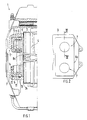
- Fig. 1 shows a brake device 1 of a vehicle wheel, which comprises a brake caliper 2 with guided brake shoes 3, between which a brake disc 4 is arranged. Via hydraulically actuated actuating pistons 5, these are pressed against the brake disk 4 during the braking process.
- each actuating piston 5 there is a concentric bore 6 facing the brake shoe 3, in which a cylindrical insert 7 is arranged.
- a cylindrical insert 7 At its front end facing the brake shoe 3, it comprises an element covering the piston end face 9 in the form of a plate-shaped intermediate layer 8a which is directly opposite the rear brake shoe surface 24.
- the insert 7 is with a radial clearance 11 to the inner peripheral surface 13 and with an axial clearance 12 to the bottom surface 14 in the Bore 6 held, wherein it is supported on the plate-shaped intermediate layer 8a to the piston end face 9.
- the intermediate layer 8a is connected to the two insert parts 7, e.g. by riveting, screwing, gluing or similar connection processes or by a positive connection.
- the intermediate layer 8a is made of a metallic material and has thin friction-increasing layers on both sides, e.g. Rubber layers 22 and 23 or paint layers covered.
- the size of the intermediate layer 8a corresponds approximately to the rear surface 24 of the brake shoe 3, so that a targeted damping of circumferential frictional vibrations of the brake shoe 3 is achieved.
- connection of the plate-shaped intermediate layer 8a can also take place via a positive connection between the insert part and the intermediate layer 8a.
- the intermediate layer 8a has a sleeve-shaped expression 20, which clampingly engages over a front cylindrical region 21 of the insert part 7, as shown in FIG. 4.
- the end face 9 of the actuating piston 5 can also be provided with teeth 25 to increase the friction, which is shown in more detail in FIG. 3.
- the insert part 7 can be covered with a material with increased friction in accordance with the plate-shaped intermediate layer 8.
Landscapes
- Engineering & Computer Science (AREA)
- General Engineering & Computer Science (AREA)
- Mechanical Engineering (AREA)
- Braking Arrangements (AREA)
Claims (7)
- Frein à disque (1) pour véhicule automobile comportant des mâchoires de frein (3) guidées dans un étrier de frein (2), des deux côtés d'un disque de frein (4), lesquelles mâchoires sont reliées à des pistons d'actionnement (5) à commande hydraulique, chaque piston d'actionnement présentant un alésage (6) dirigé vers la mâchoire de frein, alésage dans lequel est placé un insert cylindrique (7) qui comporte un élément recouvrant la face frontale de piston et qui est maintenu avec un certain jeu par rapport à la surface périphérique intérieure et à la surface de fond de l'alésage, caractérisé en ce que l'élément est constitué par un intercalaire (8a) en forme de plaque qui est solidaire des deux inserts cylindriques (7).
- Frein à disque selon la revendication 1, caractérisé en ce que l'intercalaire (8a) est en métal et est pourvu d'une couche (22) augmentant la friction sur au moins la surface tournée vers la face arrière (24) de la mâchoire de frein (3).
- Frein à disque selon la revendication 1 ou 2, caractérisé en ce que des couches augmentant la friction (22 et 23) sont prévues sur les deux faces de l'intercalaire (8a) et sont réalisées dans un matériau caoutchouteux.
- Frein à disque selon la revendication 1 ou 2, caractérisé en ce que les couches augmentant la friction sont réalisées dans une couche de laque.
- Frein à disque selon une ou plusieurs des revendications précédentes, caractérisé en ce que l'intercalaire (8a) est solidaire des inserts (7) et présente des dimensions correspondant à peu près à celles de la face arrière (24) de la mâchoire de frein (3).
- Frein à disque selon une ou plusieurs des revendications précédentes, caractérisé en ce que l'intercalaire (8a) en forme de plaque est relié par concordance de forme avec un moins un insert (7), de manière qu'une partie comprimée (20) en forme de douille de l'intercalaire (8a) passe sur une zone cylindrique (21) avant, étagée, de l'insert (7), en le serrant.
- Frein à disque selon une ou plusieurs des revendications précédentes, caractérisé en ce que la face frontale de piston (9) est pourvue d'une denture (25).
Applications Claiming Priority (2)
| Application Number | Priority Date | Filing Date | Title |
|---|---|---|---|
| DE3743290 | 1987-12-19 | ||
| DE3743290 | 1987-12-19 |
Publications (2)
| Publication Number | Publication Date |
|---|---|
| EP0321652A1 EP0321652A1 (fr) | 1989-06-28 |
| EP0321652B1 true EP0321652B1 (fr) | 1991-11-06 |
Family
ID=6343109
Family Applications (1)
| Application Number | Title | Priority Date | Filing Date |
|---|---|---|---|
| EP88113650A Expired - Lifetime EP0321652B1 (fr) | 1987-12-19 | 1988-08-23 | Dispositif de freinage |
Country Status (4)
| Country | Link |
|---|---|
| US (1) | US4886147A (fr) |
| EP (1) | EP0321652B1 (fr) |
| JP (1) | JPH023715A (fr) |
| DE (2) | DE8717512U1 (fr) |
Families Citing this family (8)
| Publication number | Priority date | Publication date | Assignee | Title |
|---|---|---|---|---|
| DE3927015A1 (de) * | 1989-08-16 | 1991-02-21 | Teves Gmbh Alfred | Teilbelag-scheibenbremse mit geraeuschgedaempften bremsbacken |
| DE9002441U1 (de) * | 1990-03-02 | 1990-05-03 | Dr.Ing.H.C. F. Porsche Ag, 7000 Stuttgart | Befestigungsvorrichtung für einen Massentilger |
| JPH05187464A (ja) * | 1992-01-13 | 1993-07-27 | Sumitomo Electric Ind Ltd | ディスクブレーキ |
| AU6864000A (en) * | 2000-08-07 | 2002-02-18 | Freni Brembo Spa | Brake pad for disk brake |
| DE10106177B4 (de) * | 2001-02-10 | 2013-02-21 | Dr. Ing. H.C. F. Porsche Aktiengesellschaft | Scheibenbremse für Fahrzeuge, insbesondere Kraftfahrzeuge |
| JP4714642B2 (ja) * | 2005-08-31 | 2011-06-29 | 曙ブレーキ工業株式会社 | ディスクブレーキパッド |
| US20080060474A1 (en) * | 2006-09-07 | 2008-03-13 | Katsumoto Mizukawa | Gearless Differential in an Integrated Hydrostatic Transmission |
| IT1394563B1 (it) * | 2009-06-23 | 2012-07-05 | Freni Brembo Spa | Dispositivo per smorzare le vibrazioni in una pastiglia di un freno a disco |
Family Cites Families (15)
| Publication number | Priority date | Publication date | Assignee | Title |
|---|---|---|---|---|
| US3684061A (en) * | 1969-05-08 | 1972-08-15 | Toyota Motor Sales Co Ltd | Disc brake |
| JPS548820B1 (fr) * | 1969-09-29 | 1979-04-19 | ||
| US3885651A (en) * | 1973-04-30 | 1975-05-27 | Ferodo Sa | Brake assembly |
| US3918555A (en) * | 1974-01-22 | 1975-11-11 | Girling Ltd | Apparatus for locating a friction pad assembly to a support member |
| DE2427040B2 (de) * | 1974-06-05 | 1979-01-11 | Abex Pagid Reibbelag Gmbh, 4300 Essen | Bremskörper für Scheibenbremsen |
| DE2508720A1 (de) * | 1975-02-28 | 1976-09-09 | Prodak Kg I G Guenther Hoffman | Verfahren zur oberflaechenbehandlung der rueckseiten von bremstraegerplatten bei kfz- oder sonstigen scheibenbremsbelaegen durch kunststoffbeschichtung zum erzielen besonderer wirkungen, d.h. zur beseitigung von quietschgeraeuschen |
| US4098951A (en) * | 1976-09-20 | 1978-07-04 | Interpolymer Corporation | Process for eliminating squeal in disc brakes |
| DE2722194A1 (de) * | 1977-05-17 | 1978-11-30 | Textar Gmbh | Scheibenbremse, insbesondere teilbelagscheibenbremse |
| GB1589118A (en) * | 1977-08-05 | 1981-05-07 | Girling Ltd | Disc brakes |
| DE2854247A1 (de) * | 1978-12-15 | 1980-06-26 | Knorr Bremse Gmbh | Vorrichtung zur waermeisolierung an der betaetigungseinrichtung einer scheibenbremse, insbesondere am hydraulisch beaufschlagbaren kolben einer teilbelagscheibenbremse |
| US4373615A (en) * | 1981-01-26 | 1983-02-15 | General Motors Corporation | Laminated disc brake pad assembly |
| DE3339809A1 (de) * | 1982-11-03 | 1984-05-03 | Ferodo Ltd., Manchester | Beilagenausbildung fuer scheibenbremsbelege |
| DE3411233A1 (de) * | 1984-03-27 | 1985-10-10 | Alfred Teves Gmbh, 6000 Frankfurt | Kolben fuer eine scheibenbremse |
| JPS6181021U (fr) * | 1984-10-31 | 1986-05-29 | ||
| DE8700102U1 (de) * | 1986-01-10 | 1987-05-14 | Textar Gmbh, 5090 Leverkusen | Teilbelagscheibenbremse mit Dämpfungselement |
-
1987
- 1987-12-19 DE DE8717512U patent/DE8717512U1/de not_active Expired
-
1988
- 1988-08-23 DE DE8888113650T patent/DE3866090D1/de not_active Expired - Lifetime
- 1988-08-23 EP EP88113650A patent/EP0321652B1/fr not_active Expired - Lifetime
- 1988-12-16 JP JP63316608A patent/JPH023715A/ja active Pending
- 1988-12-19 US US07/286,165 patent/US4886147A/en not_active Expired - Fee Related
Also Published As
| Publication number | Publication date |
|---|---|
| DE8717512U1 (de) | 1989-01-05 |
| US4886147A (en) | 1989-12-12 |
| DE3866090D1 (de) | 1991-12-12 |
| JPH023715A (ja) | 1990-01-09 |
| EP0321652A1 (fr) | 1989-06-28 |
Similar Documents
| Publication | Publication Date | Title |
|---|---|---|
| EP2118512B1 (fr) | Frein à disque, notamment pour un véhicule utilitaire | |
| EP0849488B1 (fr) | Patin de frein | |
| DE2502459B2 (de) | Dämpfungselement mit mindestens einer weichelastischen Dämpfungsschicht für Teilbelagscheibenbremsen | |
| DE2713377A1 (de) | Scheibenbremse fuer fahrzeuge | |
| DE3333670A1 (de) | Schwimmsattelbremse fuer kraftfahrzeuge | |
| DE19810593A1 (de) | Radbremse mit kombinierter elektrisch betätigbarer Feststellbremse und hydraulisch betätigbarer Betriebsbremse | |
| EP0321652B1 (fr) | Dispositif de freinage | |
| DE3744341A1 (de) | Scheibenbremsenanordnung | |
| DE4307954C2 (de) | Scheibenbremse und Bremsbelagklammer | |
| DE3044393A1 (de) | Teilbelag-scheibenbremse | |
| DE1289692B (de) | Druckmittelbetaetigte Teilbelagscheibenbremse, insbesondere fuer Kraftfahrzeuge | |
| DE4418955B4 (de) | Festsattel-Teilbelagsscheibenbremse für Kraftfahrzeuge | |
| EP0322530B1 (fr) | Dispositif de freinage | |
| EP0316521B1 (fr) | Dispositif de freinage | |
| DE3247593A1 (de) | Scheibenbremse | |
| DE19707715C2 (de) | Scheibenbremse an einem Kraftfahrzeug | |
| DE4203173B4 (de) | Innenbacken-Trommelbremse für Kraftfahrzeuge | |
| DE10031808A1 (de) | Teilbelagscheibenbremse mit einer Haltevorrichtung für einen Bremsbelag | |
| EP0872660B1 (fr) | Dispositif d'amortissement des vibrations d'un patin de frein à disque | |
| EP1691101B1 (fr) | Frein multi-disques pour véhicules, en particulier frein à deux disques pour véhicules automobiles | |
| DE19602888C1 (de) | Bremsbacke, insbesondere für Nutzfahrzeug-Scheibenbremsen | |
| DE10031904C1 (de) | Kolbeneinsatz zur Dämpfung von Bremsgeräuschen | |
| DE6805501U (de) | Scheibenbremse, insbesondere teilbelagscheibenbremse | |
| DE1804115A1 (de) | Bremsbelagrueckenplatte fuer Scheibenbremsen | |
| DE60010621T2 (de) | Bremseinheit für ein Schienenfahrzeug und Drehgestell eines Schienenfahrzeuges mit dieser Vorrichtung |
Legal Events
| Date | Code | Title | Description |
|---|---|---|---|
| PUAI | Public reference made under article 153(3) epc to a published international application that has entered the european phase |
Free format text: ORIGINAL CODE: 0009012 |
|
| AK | Designated contracting states |
Kind code of ref document: A1 Designated state(s): DE FR GB IT SE |
|
| 17P | Request for examination filed |
Effective date: 19891027 |
|
| 17Q | First examination report despatched |
Effective date: 19901217 |
|
| GRAA | (expected) grant |
Free format text: ORIGINAL CODE: 0009210 |
|
| AK | Designated contracting states |
Kind code of ref document: B1 Designated state(s): DE FR GB IT SE |
|
| REF | Corresponds to: |
Ref document number: 3866090 Country of ref document: DE Date of ref document: 19911212 |
|
| ITF | It: translation for a ep patent filed | ||
| GBT | Gb: translation of ep patent filed (gb section 77(6)(a)/1977) | ||
| ET | Fr: translation filed | ||
| PGFP | Annual fee paid to national office [announced via postgrant information from national office to epo] |
Ref country code: SE Payment date: 19920724 Year of fee payment: 5 |
|
| PGFP | Annual fee paid to national office [announced via postgrant information from national office to epo] |
Ref country code: FR Payment date: 19920729 Year of fee payment: 5 |
|
| PGFP | Annual fee paid to national office [announced via postgrant information from national office to epo] |
Ref country code: DE Payment date: 19920805 Year of fee payment: 5 |
|
| PGFP | Annual fee paid to national office [announced via postgrant information from national office to epo] |
Ref country code: GB Payment date: 19920812 Year of fee payment: 5 |
|
| PLBE | No opposition filed within time limit |
Free format text: ORIGINAL CODE: 0009261 |
|
| STAA | Information on the status of an ep patent application or granted ep patent |
Free format text: STATUS: NO OPPOSITION FILED WITHIN TIME LIMIT |
|
| 26N | No opposition filed | ||
| PG25 | Lapsed in a contracting state [announced via postgrant information from national office to epo] |
Ref country code: GB Effective date: 19930823 |
|
| PG25 | Lapsed in a contracting state [announced via postgrant information from national office to epo] |
Ref country code: SE Effective date: 19930824 |
|
| GBPC | Gb: european patent ceased through non-payment of renewal fee |
Effective date: 19930823 |
|
| PG25 | Lapsed in a contracting state [announced via postgrant information from national office to epo] |
Ref country code: FR Effective date: 19940429 |
|
| PG25 | Lapsed in a contracting state [announced via postgrant information from national office to epo] |
Ref country code: DE Effective date: 19940503 |
|
| REG | Reference to a national code |
Ref country code: FR Ref legal event code: ST |
|
| EUG | Se: european patent has lapsed |
Ref document number: 88113650.1 Effective date: 19940310 |
|
| PG25 | Lapsed in a contracting state [announced via postgrant information from national office to epo] |
Ref country code: IT Free format text: LAPSE BECAUSE OF NON-PAYMENT OF DUE FEES;WARNING: LAPSES OF ITALIAN PATENTS WITH EFFECTIVE DATE BEFORE 2007 MAY HAVE OCCURRED AT ANY TIME BEFORE 2007. THE CORRECT EFFECTIVE DATE MAY BE DIFFERENT FROM THE ONE RECORDED. Effective date: 20050823 |