EP0321677A1 - Bestandteile für Tintenzuführkreis für einen Tintenstrahldruckkopf - Google Patents
Bestandteile für Tintenzuführkreis für einen Tintenstrahldruckkopf Download PDFInfo
- Publication number
- EP0321677A1 EP0321677A1 EP88117797A EP88117797A EP0321677A1 EP 0321677 A1 EP0321677 A1 EP 0321677A1 EP 88117797 A EP88117797 A EP 88117797A EP 88117797 A EP88117797 A EP 88117797A EP 0321677 A1 EP0321677 A1 EP 0321677A1
- Authority
- EP
- European Patent Office
- Prior art keywords
- ink
- valves
- variable volume
- piston
- intended
- Prior art date
- Legal status (The legal status is an assumption and is not a legal conclusion. Google has not performed a legal analysis and makes no representation as to the accuracy of the status listed.)
- Granted
Links
- 239000012528 membrane Substances 0.000 claims abstract description 12
- 239000007787 solid Substances 0.000 claims abstract description 4
- 238000007641 inkjet printing Methods 0.000 claims abstract description 3
- 239000002904 solvent Substances 0.000 claims description 8
- 238000011084 recovery Methods 0.000 claims description 6
- 239000000463 material Substances 0.000 claims description 5
- 239000000126 substance Substances 0.000 claims description 4
- 238000004891 communication Methods 0.000 claims description 2
- 239000012530 fluid Substances 0.000 description 10
- 238000005259 measurement Methods 0.000 description 9
- 238000007789 sealing Methods 0.000 description 4
- 238000009434 installation Methods 0.000 description 3
- 230000003068 static effect Effects 0.000 description 3
- 239000004734 Polyphenylene sulfide Substances 0.000 description 2
- 238000009530 blood pressure measurement Methods 0.000 description 2
- 238000010586 diagram Methods 0.000 description 2
- 238000000034 method Methods 0.000 description 2
- 229920000069 polyphenylene sulfide Polymers 0.000 description 2
- 238000005086 pumping Methods 0.000 description 2
- 241001080024 Telles Species 0.000 description 1
- 239000006096 absorbing agent Substances 0.000 description 1
- 230000000903 blocking effect Effects 0.000 description 1
- 238000004140 cleaning Methods 0.000 description 1
- 230000006835 compression Effects 0.000 description 1
- 238000007906 compression Methods 0.000 description 1
- 230000007423 decrease Effects 0.000 description 1
- 238000006073 displacement reaction Methods 0.000 description 1
- 239000012777 electrically insulating material Substances 0.000 description 1
- 230000008020 evaporation Effects 0.000 description 1
- 238000001704 evaporation Methods 0.000 description 1
- 230000012447 hatching Effects 0.000 description 1
- 239000011810 insulating material Substances 0.000 description 1
- 210000000056 organ Anatomy 0.000 description 1
- 230000035515 penetration Effects 0.000 description 1
- 238000004064 recycling Methods 0.000 description 1
- 230000008929 regeneration Effects 0.000 description 1
- 238000011069 regeneration method Methods 0.000 description 1
- 230000002441 reversible effect Effects 0.000 description 1
- 230000035939 shock Effects 0.000 description 1
Images



Classifications
-
- B—PERFORMING OPERATIONS; TRANSPORTING
- B41—PRINTING; LINING MACHINES; TYPEWRITERS; STAMPS
- B41J—TYPEWRITERS; SELECTIVE PRINTING MECHANISMS, i.e. MECHANISMS PRINTING OTHERWISE THAN FROM A FORME; CORRECTION OF TYPOGRAPHICAL ERRORS
- B41J2/00—Typewriters or selective printing mechanisms characterised by the printing or marking process for which they are designed
- B41J2/005—Typewriters or selective printing mechanisms characterised by the printing or marking process for which they are designed characterised by bringing liquid or particles selectively into contact with a printing material
-
- B—PERFORMING OPERATIONS; TRANSPORTING
- B41—PRINTING; LINING MACHINES; TYPEWRITERS; STAMPS
- B41J—TYPEWRITERS; SELECTIVE PRINTING MECHANISMS, i.e. MECHANISMS PRINTING OTHERWISE THAN FROM A FORME; CORRECTION OF TYPOGRAPHICAL ERRORS
- B41J2/00—Typewriters or selective printing mechanisms characterised by the printing or marking process for which they are designed
- B41J2/005—Typewriters or selective printing mechanisms characterised by the printing or marking process for which they are designed characterised by bringing liquid or particles selectively into contact with a printing material
- B41J2/01—Ink jet
- B41J2/17—Ink jet characterised by ink handling
- B41J2/175—Ink supply systems ; Circuit parts therefor
-
- B—PERFORMING OPERATIONS; TRANSPORTING
- B41—PRINTING; LINING MACHINES; TYPEWRITERS; STAMPS
- B41J—TYPEWRITERS; SELECTIVE PRINTING MECHANISMS, i.e. MECHANISMS PRINTING OTHERWISE THAN FROM A FORME; CORRECTION OF TYPOGRAPHICAL ERRORS
- B41J2/00—Typewriters or selective printing mechanisms characterised by the printing or marking process for which they are designed
- B41J2/005—Typewriters or selective printing mechanisms characterised by the printing or marking process for which they are designed characterised by bringing liquid or particles selectively into contact with a printing material
- B41J2/01—Ink jet
- B41J2/015—Ink jet characterised by the jet generation process
- B41J2/04—Ink jet characterised by the jet generation process generating single droplets or particles on demand
- B41J2/045—Ink jet characterised by the jet generation process generating single droplets or particles on demand by pressure, e.g. electromechanical transducers
- B41J2/05—Ink jet characterised by the jet generation process generating single droplets or particles on demand by pressure, e.g. electromechanical transducers produced by the application of heat
Definitions
- the invention relates to a device intended to receive a combination of two variable volume chambers and a plurality of valves for constituting an ink supply circuit of an ink jet print head.
- the present invention aims to solve this problem and relates to an arrangement of all the means used in a structure easy to produce, simple and leading to an extremely compact final device.
- the invention relates more precisely to a device intended to receive two variable volume chambers and a pressure sensor, cooperating with a plurality of valves and valve-restriction pairs to ensure the functions inherent in the proper functioning of a supply circuit in ink from an inkjet print head and ink recovery not used at the recovery gutter; device characterized in that it consists of a solid monobloc piece of material resistant to chemical attack, in which are made: - on the one hand, a central cylindrical housing comprising two zones of diameter ⁇ 1 and ⁇ 2 in which a piston (P) can move, constituted by the stacking of two pieces of diameter ⁇ 1 and ⁇ 2 delimiting within these two zones, thanks to two waterproof membranes, the two variable volume chambers; - on the other hand, a plurality of cavities intended to receive the valves; - finally, a housing intended to receive the pressure sensor.
- a solid monobloc piece of material resistant to chemical attack in which are made: - on the one hand, a central cylindrical housing comprising two zones of diameter ⁇
- a cell as described in the two cited patent applications is illustrated by means of Figures 1a and 1b. It essentially consists of a chamber (1) with variable volume as a function of the displacement of a piston (P). The latter is mechanically connected by means (2) to an eccentric (3) driven by a stepping motor (4).
- This variable volume (1) is connected on the one hand to a pressure sensor (5), and on the other hand by a pipe (6) to one, two or more valves electrically controlled by coils (b). Only two valves (7) and (9) are represented in FIGS. 1a and 1b, but this number is not restrictive and the application described below will moreover clearly show the use of a plurality of valves associated with a single room.
- valves accept both directions of fluid flow and are normally closed in the absence of an electrical signal.
- the position of the drawer (t) shows for example that the valve (7) is in the blocking position in Figure 1b and in the open position in the figure 1a, and vice versa for the valve (9).
- These restrictions are designed so as to create a pressure difference at their ends when a flow of fluid of non-zero viscosity passes through them, which can be expressed in terms of pressure drop. They are capable in particular of demonstrating in the form of a pressure difference (..P), the viscosity of the fluid during a pulse of fluid flow.
- restrictions may for example consist of a tube integrated in series in the hydraulic circuit, this tube having a length significantly greater than the diameter of said tube.
- the length is approximately 15 times the diameter of the tube through which the fluid passes.
- the arrows (F3) and (F4) symbolize the flow.
- the generation of a fluid flow is done in two half-cycles.
- the first ( Figure 1a) consists in controlling the opening of the valve (7) during the half-turn of the motor rotor from a 0 ° position to a 180 ° position, i.e. the time when the volume of the chamber (1) increases; the fluid is sucked in (arrow (F3).
- the second half-cycle ( Figure 1b) consists in controlling the opening of the valve (9) during the next half-turn of the motor rotor from 180 ° to 360 °, i.e. time the volume of the chamber decreases; the fluid is discharged (arrow F4).
- the configuration of a circuit implementing such a cell allows the direct measurement of a pressure by means of the sensor (5) by direct connection of the chamber (1) with the member whose pressure.
- the valve which controls this organ located downstream is then maintained in the open position, the engine is stopped and the pressure sensor (5) is then directly in communication, via the chamber, with the said member.
- FIG. 2 An alternative embodiment of such a circuit is illustrated by means of FIG. 2 in a static configuration, all the valves being in the closed position.
- This circuit includes four tanks, two of which are removable.
- the reservoir (15) is a cartridge containing ink (30) in reserve, not yet used.
- the reservoir (15) is removable.
- the reservoir (16) is a cartridge containing the pure solvent (31) of the ink used.
- This reserve solvent (31) makes it possible to top up the solvent necessary to maintain the viscosity of the ink used and recycled in the system. Maintaining the viscosity of the ink of the jet, is linked to an evaporation of the solvent during recycling of the ink.
- This reservoir (16) is also removable.
- the reservoir (18) containing the ink (34) functionally fulfills the role of a pressure accumulator which is used in order to transform the pulsed flow rate of the cell when it is used in the pumping cell, into a constant flow rate at fixed pressure, and directly intended for forming the jet (21).
- This reservoir contains a pocket of air (180) under pressure which acts as a shock absorber. This air pocket (180) is renewed each time the printer is started.
- the role of the reservoir (17) is to receive the recovery ink (33) and the air returning from the gutter (22), and to separate them.
- the ink necessary to maintain the pressure in the accumulator (18) is taken from this reservoir.
- Each of these four reservoirs (15, 16, 17, 18) is connected, by a general pipe (66), to a first variable-volume chamber (1) by means of a valve-restriction pair (9-10 ) for the reservoir (18); (7-8) for the reservoir (17); (11-12) for the tank (16); and (13-14) for the reservoir (15).
- This set the heart of which is the chamber (1), bears the general reference (A).
- a second variable volume chamber (23) also cooperates with a plurality of valves. This combination is referenced (B).
- This second chamber (23) is combined with a set of two valves (24,25).
- This chamber being mechanically coupled to the eccentric (3) common to the first chamber (1), the synchronism of the valves which are attached to it, results from the synchronism of the chamber (1).
- a pipe (220) connects the tank (17), called the buffer tank, directly to the recovery gutter (22). This reservoir (17) can be placed under vacuum.
- a valve (26) is connected on one side to the pipe (66), and on the other to a condenser (300) comprising a receptacle for the condensate (301) and an evacuation (303) of volatile products.
- the pressure sensor (5) is connected to this first chamber (1) and allows a whole set of controls and measurements.
- this supply circuit has only one sensor, the pressure sensor (5), and that this single sensor (5) allows all the measures necessary for the proper functioning of the assembly, namely the pressure measurement of the ink supplying the jet, the viscosity measurement of the ink, the level control of the reservoir (18) during the regeneration of the air pocket, measurement of empty tank level (17), measurement of low level and empty level of solvent tank (16), measurement of ink viscosity of tank (15) linked parameter in particular at temperature, the measurement of the low level and of the empty level of the ink tank (15), the synchronism of operation of the valves with the position of the motor rotor (4).
- this single pressure sensor (5) alone replaces all the sensors that are necessarily encountered in supply circuits of currently known types.
- valves (19) and (28) are directly linked to the operation of the jet (21) emitted by the print head (T) and are part of the known art, in particular by French patent application 8316440 filed by the Applicant and published under the number 2.553.341. For this, this combination is fictitiously isolated from the rest of the circuit by means of a rectangle (150) in broken lines.
- the valve (19) is respectively connected to the pressure tank (18) on the one hand, and to the head (T) which generates the ink jet (21) on the other hand, and the valve (28 ) is connected to this head (T) and to the reservoir (17) via the pipe (170).
- the motor (4) rotates at constant speed cyclically, so that the two variable volume chambers (1) and (23) which are mechanically coupled, each generate their volume cyclically.
- This rotation cycle presents at each turn, a stop during the time necessary to the measurement of a static pressure, pressure measurement not influenced by the differential pressures induced by flow rates in restrictions (8), (10), (12) and (14).
- This allocated time allows the measurement of the static pressures, of the ink of the cartridge (30), of the solvent of the cartridge (31), and of the ink under pressure (34) of the reservoir (18).
- the present invention relates to a device intended to receive all the elements of the ink circuit previously described and directly intended to cooperate with the two chambers (1) and (23) belonging respectively to the element (A) said pressure pump , and to element (B) said vacuum pump.
- this device (100) consists of a single piece of parallelepipedal shape made of an electrically insulating material and resistant to chemical attack such as for example Polyphenylene Sulfide said PPS.
- the device (100) according to the invention is illustrated firstly by means of FIGS. 3, 4 and 5 which, by drawing artifices, make it possible to see the housings and cavities produced inside the one-piece part by removal of material which, in reality, surrounds these dwellings. This representation is made for the sake of clarity and for a better understanding of the invention, without having to resort to too high a number of sections and sections which would weigh down and confuse the description.
- the housing or the cavity shown bears the reference of the element which occupies it in reality: this is the case, for example, of the piston (P ) and its housing (202).
- This part (100) therefore comprises, produced in its mass, a plurality of housings and cavities distributed as follows: - a central cylindrical housing (202) comprising two zones of diameter ( ⁇ 1) and ( ⁇ 2), in which the piston (P) can move, allows the delimitation, in combination with two membranes visible in FIG.
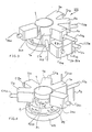
- Figure 3 shows the device (100) in one piece oriented so that the eye of the observer sees the upper plane of the housing intended to receive the pressure sensor (5) and, in the foreground, all of the cavities radial star (11a, 13a, 9a, 7a, 26a) and the double cavity (24-25) a , the central housing (202) thus being partially hidden by all of these cavities.
- FIG. 4 shows this monobloc device (100) oriented differently so that the eye of the observer sees, this time, in the background, all of the radial cavities and, in the foreground, the housing receiving the pressure sensor (5) and the base (600) carrying the piston (P) in fact constituted by the stacking of two parts (P1) and (P2) (see Figure 10).
- the function of the holes (t1, t2 ... t n ) illustrated in particular in FIG. 4 will also be defined later.
- the pipes are also made in the mass of the one-piece device (100). Their outings, which lead in variable volume chambers, bear the index (b) ( Figures 8 and 9); their opposite outputs bear the indices (a) such as (C 26a , C 11a , C 13a , C 9a , C 25a , C 24a , C 7a ).
- indices (a) such as (C 26a , C 11a , C 13a , C 9a , C 25a , C 24a , C 7a ).
- FIG. 5 illustrates the one-piece device (100) already described by means of the two figures 3 and 4, but this time the observer sees it in an opposite position, the radial cavities are seen below.
- the two additional cavities (28a) and (28b) which have been, for reasons of clarity, deliberately omitted in Figures 3 and 4.
- valves (13, 11, 7, 9, 19, 28, 24, 25, 26) are embedded in their respective cavities, for example and without this being limiting in the manner illustrated by the two figures 6 and 7.
- the hatching (M) here symbolizes the material being absent in FIGS. 3, 4 and 5, as has been said previously.
- Two O-rings (j1) and (j2) provide sealing.
- a holding system (140a) pushes on the valve concerned, the valve (13) for example, of diameter (d) to keep it in its housing.
- This system (140a) can be integral with the flange (140) which holds the sensor (5) in place ( Figure 10) and thus hold all the referenced valves (11, 9, 7 and 26).
- Figure 6 is a longitudinal section and Figure 7 is a section transverse. This method of fixing the valves is not limiting. As has just been said, they are therefore in-line electromagnetic valves with reversible operation.
- FIG. 8 illustrates a sectional view of this device (100), made at the level of the variable volume chamber (1) (element A).
- This section takes into account the presence of the material (M) absent in the preceding figures 3 to 5.
- the section of the device (100) is square.
- FIG. 9 illustrates a sectional view of the device (100) produced at the level of the variable volume chamber (23) (element B) where the double cavity (24,25) a is represented with its two outputs (C 24a ; C 24b ) and (C 25a ; C 25b ) as well as the two cavities (28a) and (19a). All the valves and the pipes of the device (100) are connected to each other and to the various reservoirs as well as to the print head, in an exemplary embodiment that is in no way limitative, according to the diagram illustrated by means of FIG. 2.
- such a device (100), as shown in Figure 10 which is a sectional view, is intended to cooperate with a reservoir block (300) as is now described.
- the device (100) therefore consists of a solid monolithic block in which we find all the cavities previously described.
- a pipe (Cp) connects the pressure sensor (5) with the variable volume chamber (1).
- a flange (140) holds this sensor (5) in place and includes profiles (140 a ) serving as supports for the valves such as (26) intended to be embedded in the cavity (C26 a ).
- the piston (P), as has been said previously, is constituted by the stacking of a base (600) and two parts (P2) of diameter ( ⁇ 2) and (P1) of diameter ( ⁇ 1).
- the first part (P1) delimits thanks to the installation of a first sealing membrane (m1) and a flange (bd1), the variable volume chamber (1).
- the second part (P2) thanks to the installation of a second sealing membrane (m2) and a second flange (bd2), delimits the variable volume chamber (23).
- a set of screws passing through the holes (t1) to (t n ) already mentioned maintains the two flanges (bd1) and (bd2) which pinch the two membranes (m1) and (m2) respectively.
- the piston (P) is connected via the base (600) to a connecting rod (500) connected via an eccentric (3) supported by a bearing (181) to a motor (4) carried by an engine support (171).
- the one-piece reservoir block (300) is made, like the device (100), of insulating material and resistant to chemical attack, and is secured to this device (100) by any known means.
- the block (300) is disposed between the engine block (170) and the device (100) and comprises two compartments which perform the function of the tanks (17) and (18), and a passage (167) through which the connecting rod (500 ).
- the reservoir block (300) is positioned between the engine block (170) and the device (100).
- This arrangement makes it possible to obtain a maximum length of the connecting rod (500).
- the greater this length the smaller the angle that this rod will guide at one of these ends by the eccentric (3) and at the other by the part (P1) of the piston (P), and the more precise the guidance of this piston (P), all of which is now in an area of isostatic mechanics with very remarkable compactness qualities.
- the cartridge holders (157) On the sides of the device (100) are arranged the cartridge holders (157) (only one is visible in this figure), the second being disposed in front of the section in FIG. 10. These are the cartridge holders receiving the ink (15) and solvent (16) cartridges. According to a characteristic of the invention, these cartridges are removable and the ink is taken at a trocar (90) whose function is to penetrate a membrane provided for this purpose in the cartridge, pre-perforated EPT membrane using a very fine needle. Under these conditions, the penetration of the trocar (90) having been made without tearing, the sealing of the cartridge is automatically found when the user removes the latter.
- valves are arranged in a star, as has been seen previously, at the periphery of the variable volume chambers (1) and (23). Under these conditions, we obtain a dead volume of the chamber (1) as low as possible, which leads to a high compression ratio: if there is a little air in the chamber, we can still go up pressure.
- a device (100) according to the invention is extremely compact and comprises in its mass all the cavities and housings necessary for the installation of all the valves and of the piston delimiting the two variable volume chambers as well as the pressure sensor. It also includes in its mass the maximum number of pipes leading to these rooms and to the outside.
- such a cell according to the invention allows access to multiple functions although its structure is extremely compact and its operation very simple. It finds its applications in particular in the field of inkjet printing, not only in the context of industrial marking, but also in that of office automation.
Landscapes
- Ink Jet (AREA)
- Particle Formation And Scattering Control In Inkjet Printers (AREA)
- Coating Apparatus (AREA)
- Inking, Control Or Cleaning Of Printing Machines (AREA)
Priority Applications (1)
| Application Number | Priority Date | Filing Date | Title |
|---|---|---|---|
| AT88117797T ATE102872T1 (de) | 1987-12-21 | 1988-10-26 | Bestandteile fuer tintenzufuehrkreis fuer einen tintenstrahldruckkopf. |
Applications Claiming Priority (2)
| Application Number | Priority Date | Filing Date | Title |
|---|---|---|---|
| FR8718127 | 1987-12-21 | ||
| FR8718127A FR2624795B1 (fr) | 1987-12-21 | 1987-12-21 | Dispositif destine a recevoir une combinaison de deux chambres a volume variable et d'une pluralite de valves pour circuit d'alimentation d'une tete d'impression a jet d'encre |
Publications (2)
| Publication Number | Publication Date |
|---|---|
| EP0321677A1 true EP0321677A1 (de) | 1989-06-28 |
| EP0321677B1 EP0321677B1 (de) | 1994-03-16 |
Family
ID=9358281
Family Applications (1)
| Application Number | Title | Priority Date | Filing Date |
|---|---|---|---|
| EP88117797A Expired - Lifetime EP0321677B1 (de) | 1987-12-21 | 1988-10-26 | Bestandteile für Tintenzuführkreis für einen Tintenstrahldruckkopf |
Country Status (13)
| Country | Link |
|---|---|
| US (1) | US5055857A (de) |
| EP (1) | EP0321677B1 (de) |
| JP (1) | JP2514086B2 (de) |
| KR (1) | KR920007215B1 (de) |
| CN (2) | CN1010202B (de) |
| AT (1) | ATE102872T1 (de) |
| AU (1) | AU602802B2 (de) |
| CA (1) | CA1288279C (de) |
| DE (1) | DE3888490T2 (de) |
| ES (1) | ES2058210T3 (de) |
| FR (1) | FR2624795B1 (de) |
| RU (1) | RU2075395C1 (de) |
| WO (1) | WO1989005728A1 (de) |
Cited By (1)
| Publication number | Priority date | Publication date | Assignee | Title |
|---|---|---|---|---|
| US5459497A (en) * | 1990-05-03 | 1995-10-17 | Domino Printing Sciences Plc | Ink supply system for continuous ink jet printer |
Families Citing this family (13)
| Publication number | Priority date | Publication date | Assignee | Title |
|---|---|---|---|---|
| DE69119179T2 (de) * | 1990-10-03 | 1996-10-17 | Canon Kk | Tintenstrahlaufzeichnungsgerät |
| JPH05197321A (ja) * | 1991-07-31 | 1993-08-06 | Canon Inc | 感光体及びこれを備える電子写真装置及びこの装置に着脱可能なプロセスカートリッジ |
| FR2698665B1 (fr) * | 1992-11-27 | 1995-02-17 | Imaje | Pompe étanche à piston. |
| FR2780336B1 (fr) * | 1998-06-29 | 2000-08-11 | Imaje Sa | Circuit d'encre, machine a jet d'encre, et machine de conditionnememnt, ou convoyeur, mettant en oeuvre un tel circuit |
| GB9822875D0 (en) * | 1998-10-21 | 1998-12-16 | Xaar Technology Ltd | Droplet deposition apparatus |
| EP1083053A1 (de) * | 1999-09-09 | 2001-03-14 | De La Rue Giori S.A. | Tintenstrahldruckvorrichtung für Tinten mit hoher Pigmentkonzentration und diese Vorrichtung gebrauchendes Tintenstrahldruckverfahren |
| JP2002264362A (ja) * | 2001-03-08 | 2002-09-18 | Seiko Instruments Inc | インクジェット式記録装置 |
| RU2212633C1 (ru) * | 2002-05-27 | 2003-09-20 | ЗАО "Институт электрокаплеструйных технологий" | Гидросистема электрокаплеструйного принтера и ее элементы |
| US7543920B2 (en) * | 2004-01-09 | 2009-06-09 | Videojet Technologies Inc. | System and method for connecting an ink bottle to an ink reservoir of an ink jet printing system |
| US7401907B2 (en) * | 2005-01-21 | 2008-07-22 | Hewlett-Packard Development Company, L.P. | Imaging device including a passive valve |
| JP6266358B2 (ja) * | 2014-01-24 | 2018-01-24 | 株式会社キーエンス | インクジェット記録装置及び長期休止のための準備方法 |
| WO2021211129A1 (en) | 2020-04-16 | 2021-10-21 | Hewlett-Packard Development Company, L.P. | Conductive connections |
| WO2021236099A1 (en) * | 2020-05-22 | 2021-11-25 | Hewlett-Packard Development Company, L.P. | Fluid channels of different types |
Citations (2)
| Publication number | Priority date | Publication date | Assignee | Title |
|---|---|---|---|---|
| DE3029089A1 (de) * | 1979-08-03 | 1981-02-05 | Sharp Kk | Kolbenpumpe, insbesondere fuer das tintenzufuehrsystem eines tintenstrahldruckers |
| US4357617A (en) * | 1978-06-29 | 1982-11-02 | Sharp Kabushiki Kaisha | Ink recirculating device of ink jet printer |
Family Cites Families (4)
| Publication number | Priority date | Publication date | Assignee | Title |
|---|---|---|---|---|
| JPS56120361A (en) * | 1980-02-28 | 1981-09-21 | Oki Electric Ind Co Ltd | Ink-circulating device |
| JPS6055322B2 (ja) * | 1981-08-17 | 1985-12-04 | 日産自動車株式会社 | 自動車のウインドモ−ル取付構造 |
| SE447222B (sv) * | 1984-12-21 | 1986-11-03 | Swedot System Ab | Elektromagnetiskt manovrerbar ventilanordning, serskilt for alstring av droppar i en vetskestralskrivare |
| FR2619753B2 (fr) * | 1986-12-10 | 1990-08-31 | Imaje Sa | Circuit d'alimentation fluide d'une tete d'impression equipee d'une cellule multifonctions comportant une chambre a volume variable |
-
1987
- 1987-12-21 FR FR8718127A patent/FR2624795B1/fr not_active Expired - Lifetime
-
1988
- 1988-10-25 WO PCT/FR1988/000522 patent/WO1989005728A1/fr not_active Ceased
- 1988-10-25 US US07/372,368 patent/US5055857A/en not_active Expired - Lifetime
- 1988-10-25 KR KR1019890701064A patent/KR920007215B1/ko not_active Expired
- 1988-10-25 JP JP63509055A patent/JP2514086B2/ja not_active Expired - Fee Related
- 1988-10-25 AU AU26291/88A patent/AU602802B2/en not_active Ceased
- 1988-10-25 RU SU884614806A patent/RU2075395C1/ru active
- 1988-10-26 DE DE3888490T patent/DE3888490T2/de not_active Expired - Fee Related
- 1988-10-26 AT AT88117797T patent/ATE102872T1/de active
- 1988-10-26 EP EP88117797A patent/EP0321677B1/de not_active Expired - Lifetime
- 1988-10-26 ES ES88117797T patent/ES2058210T3/es not_active Expired - Lifetime
- 1988-11-21 CA CA000583623A patent/CA1288279C/fr not_active Expired - Lifetime
- 1988-12-21 CN CN88108786A patent/CN1010202B/zh not_active Expired
- 1988-12-21 CN CN90102584A patent/CN1018811B/zh not_active Expired
Patent Citations (2)
| Publication number | Priority date | Publication date | Assignee | Title |
|---|---|---|---|---|
| US4357617A (en) * | 1978-06-29 | 1982-11-02 | Sharp Kabushiki Kaisha | Ink recirculating device of ink jet printer |
| DE3029089A1 (de) * | 1979-08-03 | 1981-02-05 | Sharp Kk | Kolbenpumpe, insbesondere fuer das tintenzufuehrsystem eines tintenstrahldruckers |
Non-Patent Citations (1)
| Title |
|---|
| PATENT ABSTRACTS OF JAPAN, vol. 5, no. 203 (M-103)[875], 23 décembre 1981; & JP-A-56 120 361 (OKI DENKI KOGYO K.K.) 21-09-1981 * |
Cited By (1)
| Publication number | Priority date | Publication date | Assignee | Title |
|---|---|---|---|---|
| US5459497A (en) * | 1990-05-03 | 1995-10-17 | Domino Printing Sciences Plc | Ink supply system for continuous ink jet printer |
Also Published As
| Publication number | Publication date |
|---|---|
| CN1035983A (zh) | 1989-10-04 |
| EP0321677B1 (de) | 1994-03-16 |
| CA1288279C (fr) | 1991-09-03 |
| US5055857A (en) | 1991-10-08 |
| CN1010202B (zh) | 1990-10-31 |
| KR900700295A (ko) | 1990-08-13 |
| AU2629188A (en) | 1989-07-19 |
| ES2058210T3 (es) | 1994-11-01 |
| CN1018811B (zh) | 1992-10-28 |
| CN1048817A (zh) | 1991-01-30 |
| ATE102872T1 (de) | 1994-04-15 |
| JP2514086B2 (ja) | 1996-07-10 |
| WO1989005728A1 (fr) | 1989-06-29 |
| FR2624795B1 (fr) | 1990-04-13 |
| RU2075395C1 (ru) | 1997-03-20 |
| KR920007215B1 (ko) | 1992-08-28 |
| DE3888490D1 (de) | 1994-04-21 |
| AU602802B2 (en) | 1990-10-25 |
| DE3888490T2 (de) | 1994-09-08 |
| FR2624795A1 (fr) | 1989-06-23 |
| JPH02501818A (ja) | 1990-06-21 |
Similar Documents
| Publication | Publication Date | Title |
|---|---|---|
| EP0321677B1 (de) | Bestandteile für Tintenzuführkreis für einen Tintenstrahldruckkopf | |
| EP0277453B1 (de) | Mehrzweckzelle mit einem veränderlichen Rauminhalt und damit versehene Flüssigkeitszufuhrschaltung eines Tintenstrahlschreibkopfes | |
| EP0062549B1 (de) | Vorrichtung zum Filtern von Fluiden und in dieser Vorrichtung durchgeführtes Verfahren | |
| EP0787032B1 (de) | Vorrichtung zum behandlung von flüssigkeit mittels filtration und zentrifugation | |
| EP1306560B1 (de) | Elektrohydraulischer Stellantrieb | |
| EP0447521B1 (de) | Tintenschaltung zur druckbeaufschlagung einer pigmenttinte für tintenstrahldrucker | |
| FR2744924A1 (fr) | Dispositif generateur/regulateur de pression pour pompe d'assistance cardiaque implantable du type a ballonnet de contrepression | |
| FR2879961A1 (fr) | Nettoyage d'une tete d'impression | |
| CA1250486A (fr) | Circuit d'alimentation en encre d'une tete d'impression a jet d'encre | |
| WO2009000860A1 (fr) | Pipette permettant un prelevement de liquide par mouvement de va-et-vient du piston | |
| EP0121105A1 (de) | Vorrichtung zur Filterung von Flüssigkeiten | |
| EP1030052A1 (de) | Hochdruck-Kraftstoffeinspritzsystem einer direkteinspritzenden Brennkraftmaschine | |
| FR2617286A1 (fr) | Dispositif de prelevement comportant une tete de prelevement sterilisable en position montee sur un bioreacteur | |
| EP0779876B1 (de) | Vorrichtung zur entsorgung von kraftstoffdämpfen mit verbesserter laufstabilität | |
| FR2484839A1 (fr) | Procede et dispositif pour faire circuler et pomper des liquides organo-biologiques, notamment du sang | |
| EP0942103A1 (de) | Ventileinrichtung für einen hydraulischen Motor zum Antreiben einer Masse grossens Trägheitsvermögens | |
| WO2001081909A1 (fr) | Dispositif perfectionne d'analyse d'echantillons par electrophorese multicapillaire a thermo-regulation solide/solide | |
| FR2608225A1 (fr) | Cellule a multiples fonctions comportant une chambre a volume variable, et circuit d'alimentation fluide d'une tete d'impression a jet d'encre qui en est equipe | |
| EP0617272B1 (de) | norrichtung zur Porositätsmessung eines Filterelementes | |
| FR2472945A1 (fr) | Procede et dispositif pour filtrer en continu un fluide aspire par une pompe | |
| FR2498573A1 (fr) | Appareil de stockage et de destockage automatique de numeraire | |
| EP0042774A1 (de) | Einrichtung zum Erzeugen von Hydraulikflussmengen hintereinander abgestufter Werte | |
| FR2513536A1 (fr) | Dispositif de filtration d'un liquide | |
| EP0149931A1 (de) | Filter mit mehreren Aufnahmekammern für das Filtrat und für eine andere Flüssigkeit welche durch den Rückstand den Hauptfiltrierung gebildet ist | |
| WO1987004586A1 (fr) | Dispositif pour l'injection d'un fluide dans un reseau |
Legal Events
| Date | Code | Title | Description |
|---|---|---|---|
| PUAI | Public reference made under article 153(3) epc to a published international application that has entered the european phase |
Free format text: ORIGINAL CODE: 0009012 |
|
| AK | Designated contracting states |
Kind code of ref document: A1 Designated state(s): AT BE DE ES FR GB IT NL SE |
|
| 17P | Request for examination filed |
Effective date: 19891004 |
|
| 17Q | First examination report despatched |
Effective date: 19910619 |
|
| GRAA | (expected) grant |
Free format text: ORIGINAL CODE: 0009210 |
|
| AK | Designated contracting states |
Kind code of ref document: B1 Designated state(s): AT BE DE ES FR GB IT NL SE |
|
| REF | Corresponds to: |
Ref document number: 102872 Country of ref document: AT Date of ref document: 19940415 Kind code of ref document: T |
|
| ITF | It: translation for a ep patent filed | ||
| GBT | Gb: translation of ep patent filed (gb section 77(6)(a)/1977) |
Effective date: 19940314 |
|
| REF | Corresponds to: |
Ref document number: 3888490 Country of ref document: DE Date of ref document: 19940421 |
|
| PG25 | Lapsed in a contracting state [announced via postgrant information from national office to epo] |
Ref country code: AT Effective date: 19941026 |
|
| REG | Reference to a national code |
Ref country code: ES Ref legal event code: FG2A Ref document number: 2058210 Country of ref document: ES Kind code of ref document: T3 |
|
| PLBE | No opposition filed within time limit |
Free format text: ORIGINAL CODE: 0009261 |
|
| STAA | Information on the status of an ep patent application or granted ep patent |
Free format text: STATUS: NO OPPOSITION FILED WITHIN TIME LIMIT |
|
| EAL | Se: european patent in force in sweden |
Ref document number: 88117797.6 |
|
| 26N | No opposition filed | ||
| PGFP | Annual fee paid to national office [announced via postgrant information from national office to epo] |
Ref country code: BE Payment date: 19960923 Year of fee payment: 9 |
|
| PG25 | Lapsed in a contracting state [announced via postgrant information from national office to epo] |
Ref country code: BE Free format text: LAPSE BECAUSE OF NON-PAYMENT OF DUE FEES Effective date: 19971031 |
|
| BERE | Be: lapsed |
Owner name: S.A. IMAJE Effective date: 19971031 |
|
| PGFP | Annual fee paid to national office [announced via postgrant information from national office to epo] |
Ref country code: SE Payment date: 19991011 Year of fee payment: 12 |
|
| PGFP | Annual fee paid to national office [announced via postgrant information from national office to epo] |
Ref country code: NL Payment date: 19991029 Year of fee payment: 12 |
|
| PG25 | Lapsed in a contracting state [announced via postgrant information from national office to epo] |
Ref country code: SE Free format text: THE PATENT HAS BEEN ANNULLED BY A DECISION OF A NATIONAL AUTHORITY Effective date: 20001030 |
|
| PG25 | Lapsed in a contracting state [announced via postgrant information from national office to epo] |
Ref country code: NL Free format text: LAPSE BECAUSE OF NON-PAYMENT OF DUE FEES Effective date: 20010501 |
|
| EUG | Se: european patent has lapsed |
Ref document number: 88117797.6 |
|
| NLV4 | Nl: lapsed or anulled due to non-payment of the annual fee |
Effective date: 20010501 |
|
| REG | Reference to a national code |
Ref country code: GB Ref legal event code: IF02 |
|
| PGFP | Annual fee paid to national office [announced via postgrant information from national office to epo] |
Ref country code: ES Payment date: 20040924 Year of fee payment: 17 |
|
| PGFP | Annual fee paid to national office [announced via postgrant information from national office to epo] |
Ref country code: GB Payment date: 20041020 Year of fee payment: 17 |
|
| PG25 | Lapsed in a contracting state [announced via postgrant information from national office to epo] |
Ref country code: GB Free format text: LAPSE BECAUSE OF NON-PAYMENT OF DUE FEES Effective date: 20051026 Ref country code: IT Free format text: LAPSE BECAUSE OF NON-PAYMENT OF DUE FEES;WARNING: LAPSES OF ITALIAN PATENTS WITH EFFECTIVE DATE BEFORE 2007 MAY HAVE OCCURRED AT ANY TIME BEFORE 2007. THE CORRECT EFFECTIVE DATE MAY BE DIFFERENT FROM THE ONE RECORDED. Effective date: 20051026 |
|
| PGFP | Annual fee paid to national office [announced via postgrant information from national office to epo] |
Ref country code: DE Payment date: 20051026 Year of fee payment: 18 |
|
| PG25 | Lapsed in a contracting state [announced via postgrant information from national office to epo] |
Ref country code: ES Free format text: LAPSE BECAUSE OF NON-PAYMENT OF DUE FEES Effective date: 20051027 |
|
| GBPC | Gb: european patent ceased through non-payment of renewal fee |
Effective date: 20051026 |
|
| REG | Reference to a national code |
Ref country code: ES Ref legal event code: FD2A Effective date: 20051027 |
|
| PG25 | Lapsed in a contracting state [announced via postgrant information from national office to epo] |
Ref country code: DE Free format text: LAPSE BECAUSE OF NON-PAYMENT OF DUE FEES Effective date: 20070501 |
|
| PGFP | Annual fee paid to national office [announced via postgrant information from national office to epo] |
Ref country code: FR Payment date: 20071026 Year of fee payment: 20 |