EP0321745B1 - Détecteur de photo-ionisation pour chromatographie en phase gazeuse - Google Patents
Détecteur de photo-ionisation pour chromatographie en phase gazeuse Download PDFInfo
- Publication number
- EP0321745B1 EP0321745B1 EP88119926A EP88119926A EP0321745B1 EP 0321745 B1 EP0321745 B1 EP 0321745B1 EP 88119926 A EP88119926 A EP 88119926A EP 88119926 A EP88119926 A EP 88119926A EP 0321745 B1 EP0321745 B1 EP 0321745B1
- Authority
- EP
- European Patent Office
- Prior art keywords
- detector
- photoionization
- lamp
- pid
- chamber
- Prior art date
- Legal status (The legal status is an assumption and is not a legal conclusion. Google has not performed a legal analysis and makes no representation as to the accuracy of the status listed.)
- Expired - Lifetime
Links
Images

Classifications
-
- G—PHYSICS
- G01—MEASURING; TESTING
- G01N—INVESTIGATING OR ANALYSING MATERIALS BY DETERMINING THEIR CHEMICAL OR PHYSICAL PROPERTIES
- G01N30/00—Investigating or analysing materials by separation into components using adsorption, absorption or similar phenomena or using ion-exchange, e.g. chromatography or field flow fractionation
- G01N30/02—Column chromatography
- G01N30/62—Detectors specially adapted therefor
- G01N30/64—Electrical detectors
-
- G—PHYSICS
- G01—MEASURING; TESTING
- G01N—INVESTIGATING OR ANALYSING MATERIALS BY DETERMINING THEIR CHEMICAL OR PHYSICAL PROPERTIES
- G01N27/00—Investigating or analysing materials by the use of electric, electrochemical, or magnetic means
- G01N27/62—Investigating or analysing materials by the use of electric, electrochemical, or magnetic means by investigating the ionisation of gases, e.g. aerosols; by investigating electric discharges, e.g. emission of cathode
- G01N27/64—Investigating or analysing materials by the use of electric, electrochemical, or magnetic means by investigating the ionisation of gases, e.g. aerosols; by investigating electric discharges, e.g. emission of cathode using wave or particle radiation to ionise a gas, e.g. in an ionisation chamber
- G01N27/66—Investigating or analysing materials by the use of electric, electrochemical, or magnetic means by investigating the ionisation of gases, e.g. aerosols; by investigating electric discharges, e.g. emission of cathode using wave or particle radiation to ionise a gas, e.g. in an ionisation chamber and measuring current or voltage
-
- G—PHYSICS
- G01—MEASURING; TESTING
- G01N—INVESTIGATING OR ANALYSING MATERIALS BY DETERMINING THEIR CHEMICAL OR PHYSICAL PROPERTIES
- G01N30/00—Investigating or analysing materials by separation into components using adsorption, absorption or similar phenomena or using ion-exchange, e.g. chromatography or field flow fractionation
- G01N30/02—Column chromatography
- G01N30/62—Detectors specially adapted therefor
- G01N30/64—Electrical detectors
- G01N2030/642—Electrical detectors photoionisation detectors
Definitions
- a special electrode arrangement for ion detection within a PID is the subject of U.S. Patent US-A-4,013,913, awarded to Driscoll and Spaziani.
- An electrode arrangement is disclosed in this patent where an anode and cathode are positioned, with respect to the ionizing radiation, such that an annular configuration is defined with the anode directly exposed to the radiant energy and the cathode shielded from the energy source by either a metallic or an organic plastic material.
- Such an arrangement is said to produce low noise by minimizing the creation of unwanted photoelectrons from UV radiation striking the cathode.
- a PID usually includes a radiant energy source (usually high energy UV light of approximately 10 electron volts), an ionization chamber containing ion accelerator and collecting electrodes, and electronic circuitry for driving the photon source, amplifying the ion current and driving an output device.
- the sample to be detected is passed as a gas through the ionization chamber where it is exposed to the radiant energy and ionized.
- the ions formed are accelerated and collected by the electrode structures within the ionization chamber.
- the UV lamp window is in contact with the sample stream. Although this is desirable to minimize any unswept volume (dead volume), it allows the window to become fogged by nonvolatile components in the sample stream and by polymer products formed when certain GC eluates such as glycols are irradiated by the UV light. Such window coatings reduce the amount of light reaching the sample and cause a corresponding decrease in detector sensitivity. Detector performance will eventually deteriorate below that which is acceptable and then the lamp, which is quite expensive, must be replaced or the window cleaned if possible.
- DD-A-248 880 discloses a photoionization detector comprising a UV-lamp, a lamp window, an ionization chamber having electrodes and a ceramic plate, a collector electrode and a polarizing electrode being formed as coaxial segments of a cylinder, a sweep gas inlet and a gas exit.
- An additional embodiment of the present invention provides an automatic electronic control to the ionizing lamp which regulates power to the lamp for the purpose of extending lamp life.
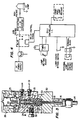
- FIGURE 1 is a schematic diagram of a system for gas chromatography utilizing the features of the present invention.
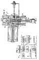
- FIGURE 2 is a cross-sectional view of the photoionization detector of the present invention.
- FIGURE 3 is a cross-sectional view, taken through lines 3-3 of FIGURE 2, of the photoionization detector of the present invention.
- FIGURE 4 is a schematic diagram of the lamp voltage control embodiment of the present invention.
- FIGURES 5(a) and 5(b) are representations of detector performance, wherein the features of the present invention are utilized.
- FIGURE 1 A block diagram of the photoionization detector of the present invention is shown in FIGURE 1.
- the PID 10 consists of three main assemblies - the lamp power supply 11, an electrometer 12 and the detector proper (hereafter referred to as detector 13).
- detector 13 the detector proper
- this invention uses the electrometer supplied in the gas chromatograph, normally installed for operating a flame ionization detector, which is a very common detector available from all major chromatograph manufacturers.
- the novel features of this invention relate to the unique design elements of the detector.
- An additional embodiment comprises the use of a "lamp saver" circuit located in the lamp power supply module.
- FIGURES 2 and 3 show cross sectional view of the detector.
- the detector 13 is interfaced to the gas chromatograph column at 14.
- the sample stream is directed from the detector inlet through the glass-lined stainless steel transfer tube 15 and transfer port into the photoionization chamber 16 defined by the polarizing electrode 17, electrode spacer 18, collector electrode 19, ceramic insert 20, electrode biscuit 21, and lamp window 22.
- the transfer tube 15 rises through a mounting block 50 into the electrode biscuit 21 thrugh a tapered seal 51.
- the tapered seal has two tapered surfaces 52, 53 which pilot against matched tapered openings in the electrode biscuit and mounting block.
- the seal also accepts the polarizing electrode 17 in a recess 55.
- the sample stream is fluidically switched away from lamp window 22 by a sweep gas entering the photoionization chamber at sweep gas inlet port 23 and exits the chamber through exit transfer 24.
- Ions created from exposure of the sample within the ionization chamber 16 by UV lamp 25 contained within lamp biscuit 26 are accelerated by polarizing electrode 17 to collector electrode 19.
- Electrical connections to the electrometer input and polarizing voltage source are made via spring-loaded connectors 27 and 28.
- a novel design feature of the PID exit port 24, 29 is that it forms the female portion of a tube connection, which enables the reactor of an electrolytic conductivity detector to be directly interfaced to the PID without the use of a transfer tube as required by conventional designs.
- the electrode biscuit contains a vent exit port 30 connected to a solenoid controlled vent valve (not shown) via the vent exit tube 31, which allows unwanted sample components to be vented from the detector photoionization chamber 16 prior to the exit port 29 and entering the ELCD reactor when installed.
- venting mechanism into the PID is an additional novel feature of this invention not found in any other PID.
- This feature when combined with the sweep gas feature, using an ELCD reaction gas as the sweep gas (i.e. hydrogen or air, depending upon ELCD mode of operation) enables the PID to provide the venting and reaction gas introduction functions of the ELCD, normally performed by the detector base of the ELCD, in addition to the normal photoionization function of the PID.
- This allows the ELCD reactor to be interfaced directly to the PID, eliminating the need for ELCD detector base and the use of any transfer tubing to interface the two detectors. In this manner an unitized PID-ELCD detector system is formed, which requires the use of only one detector port.
- the "lamp saver" circuit of the PID lamp supply is an additional embodiment of this invention.
- the operation of this feature can be understood with the aid of the simplified circuit schematic shown in FIGURE 4. Power to the UV lamp is automatically removed after a user-selectable time has elapsed unless the timer is reset by a contact closure activated by a pushbutton on the supply module or a contact closure resident on and activated by another instrument such as a gas chromatograph or a purge-and-trap sample concentrator.
- the UV lamp will remain on during the entire time the detector is in use as long as the timer is set to a time longer than the chromatograph analysis time, because a ready signal (contact closure) will be generated by the chromatograph (or ancillary instrument) when it has completed a run and is ready to begin another. If not desired, the feature can be disabled by the "lamp saver" bypass switch.
- the "lamp saver" feature is useful in the operation of the PID, because many of the UV lamps used have a fairly short life of approximately 500 to 600 hours. As a result, if one forgets to turn off the PID lamp supply and it is left on at night or for a weekend, a considerable portion of the lamp's life will be wasted.
- FIGURE 5 The performance of the invention is shown in FIGURE 5.
- Response of the PID to a mixture of aromatic and chlorinated hydrocarbon compounds pertinent to United States Environmental Protection Agency methods 601 and 602 is shown in this FIGURE 5(a).
- the response of an ELCD connected in series and functioning with the PID as an unitized detector system is shown in FIGURE 5(b).
- the excellent response of the ELCD shows that no loss in peak integrity occurs by passing the sample through the PID.
Landscapes
- Chemical & Material Sciences (AREA)
- Health & Medical Sciences (AREA)
- General Health & Medical Sciences (AREA)
- Life Sciences & Earth Sciences (AREA)
- Analytical Chemistry (AREA)
- Biochemistry (AREA)
- Physics & Mathematics (AREA)
- General Physics & Mathematics (AREA)
- Immunology (AREA)
- Pathology (AREA)
- Toxicology (AREA)
- Chemical Kinetics & Catalysis (AREA)
- Electrochemistry (AREA)
- Other Investigation Or Analysis Of Materials By Electrical Means (AREA)
Claims (6)
- Détecteur de photo-ionisation (13) connectable à un détecteur de conductivité électrolytique, ayant une chambre de photo-ionisation (16), la chambre comportant une électrode de polarisation (17), une électrode collectrice (19), une lampe (25), une fenêtre de lampe (22) et un tube de transfert (15) pour introduire un échantillon dans la chambre de photo-ionisation, et un orifice d'entrée (23) pour introduire un gaz de balayage dans la chambre de photo-ionisation, caractérisé par un orifice de sortie (24, 29) susceptible d'être relié avec l'entrée du réacteur du détecteur de conductivité électrolytique.
- Détecteur de photo-ionisation selon la revendication 1, caractérisé par ailleurs en ce que le détecteur de photo-ionisation (13) comprend en outre la lampe (25), la fenêtre de lampe (22) et l'orifice d'entrée (23) pour balayer un gaz à proximité de la fenêtre de lampe.
- Détecteur de photo-ionisation selon la revendication 1, caractérisé par ailleurs en ce que l'orifice de sortie (24, 29) est filetée intérieurement pour coopérer avec une partie filetée extérieurement de l'entrée du réacteur du détecteur de conductivité électrolytique.
- Détecteur de photo-ionisation selon la revendication 1, caractérisé par ailleurs en ce que l'orifice d'entrée (23) et l'orifice de sortie (24, 29) ont des passages qui sont de manière générale perpendiculaires au tube de transfert (15).
- Détecteur de photo-ionisation selon la revendication 1, caractérisé par ailleurs en ce que le gaz de balayage introduit dans la chambre de photo-ionisation (16) par l'orifice d'entrée (23) fait passer par voie fluidique l'échantillon loin de la fenêtre de lampe (22).
- Détecteur de photo-ionisation selon la revendication 1, caractérisé par ailleurs par un orifice d'évacuation (30) entre l'intérieur et l'extérieur de la chambre de photo-ionisation (16).
Applications Claiming Priority (2)
| Application Number | Priority Date | Filing Date | Title |
|---|---|---|---|
| US128644 | 1987-12-04 | ||
| US07/128,644 US4804846A (en) | 1987-12-04 | 1987-12-04 | Photoionization detector for gas chromatography |
Publications (3)
| Publication Number | Publication Date |
|---|---|
| EP0321745A2 EP0321745A2 (fr) | 1989-06-28 |
| EP0321745A3 EP0321745A3 (fr) | 1991-01-16 |
| EP0321745B1 true EP0321745B1 (fr) | 1995-04-12 |
Family
ID=22436304
Family Applications (1)
| Application Number | Title | Priority Date | Filing Date |
|---|---|---|---|
| EP88119926A Expired - Lifetime EP0321745B1 (fr) | 1987-12-04 | 1988-11-30 | Détecteur de photo-ionisation pour chromatographie en phase gazeuse |
Country Status (4)
| Country | Link |
|---|---|
| US (1) | US4804846A (fr) |
| EP (1) | EP0321745B1 (fr) |
| JP (1) | JPH0758282B2 (fr) |
| DE (1) | DE3853575T2 (fr) |
Families Citing this family (20)
| Publication number | Priority date | Publication date | Assignee | Title |
|---|---|---|---|---|
| US5116764A (en) * | 1988-07-26 | 1992-05-26 | Raymond Annino | Dual-column, dual-detector gas detector and analyzer |
| US5206594A (en) * | 1990-05-11 | 1993-04-27 | Mine Safety Appliances Company | Apparatus and process for improved photoionization and detection |
| US5194814A (en) * | 1991-05-22 | 1993-03-16 | Tremetrics, Inc. | Electrolytic conductivity detector |
| US5289003A (en) * | 1992-05-29 | 1994-02-22 | The United States Of America As Represented By The Secretary Of The Department Of Health And Human Services | Probe for thermospray mass spectrometry |
| WO1996002834A1 (fr) * | 1994-07-15 | 1996-02-01 | Fisons Instruments S.P.A. | Detecteur a photo-ionisation et procede associe |
| US5578271A (en) * | 1995-03-01 | 1996-11-26 | O.I. Corporation | Tandem photoionization detector and halogen specific detector |
| US6225633B1 (en) | 1998-10-22 | 2001-05-01 | Rae Systems, Inc. | Photo-ionization detector for volatile gas measurement and a method for self-cleaning the same |
| US7119342B2 (en) * | 1999-02-09 | 2006-10-10 | Syagen Technology | Interfaces for a photoionization mass spectrometer |
| US7109476B2 (en) | 1999-02-09 | 2006-09-19 | Syagen Technology | Multiple ion sources involving atmospheric pressure photoionization |
| US6630664B1 (en) * | 1999-02-09 | 2003-10-07 | Syagen Technology | Atmospheric pressure photoionizer for mass spectrometry |
| EP1226602B1 (fr) | 1999-10-29 | 2008-02-13 | MDS Inc., through its MDS Sciex Division | Photoionisation sous pression atmospherique, nouveau procede d'ionisiation pour spectrometrie de masse avec chromatographie en phase liquide |
| US6734435B2 (en) | 2001-05-29 | 2004-05-11 | Rae Systems, Inc. | Photo-ionization detector and method for continuous operation and real-time self-cleaning |
| EP1279955B2 (fr) * | 2001-07-24 | 2010-03-03 | Services Petroliers Schlumberger | Détecteur à ionisation d'hélium |
| JP2003098153A (ja) * | 2001-09-27 | 2003-04-03 | Yokogawa Electric Corp | 光イオン化検出器 |
| KR100488871B1 (ko) * | 2002-10-26 | 2005-05-11 | (주)백년기술 | 다중 광 이온화를 이용한 다채널 광이온화 검출기 |
| US8922219B2 (en) | 2010-11-30 | 2014-12-30 | General Electric Company | Photo-ionization detectors and associated methods thereof |
| RU2523765C1 (ru) * | 2012-12-24 | 2014-07-20 | Федеральное государственное бюджетное образовательное учреждение высшего профессионального образования "Тверской государственный технический университет" | Фотоионизационный детектор для газоаналитической аппаратуры |
| WO2018112733A1 (fr) * | 2016-12-20 | 2018-06-28 | Honeywell International Inc. | Protection pour électrodes dans un détecteur à photo-ionisation |
| RU174543U1 (ru) * | 2017-04-17 | 2017-10-19 | Федеральное государственное бюджетное образовательное учреждение высшего образования "Тверской государственный технический университет" | Фотоионизационный детектор газов |
| CN115360083B (zh) * | 2022-09-16 | 2025-02-21 | 苏州微木智能系统有限公司 | 一种紫外光电离源及紫外光电离方法 |
Family Cites Families (19)
| Publication number | Priority date | Publication date | Assignee | Title |
|---|---|---|---|---|
| GB989614A (en) * | 1960-09-16 | 1965-04-22 | Nat Res Dev | Improvements in or relating to the measurement of gas or vapour concentrations |
| US3238367A (en) * | 1963-02-20 | 1966-03-01 | Beckman Instruments Inc | Device for the analysis of a fluent material by bombarding the same with photoelectrons |
| JPS4219671Y1 (fr) * | 1964-02-15 | 1967-11-14 | ||
| US3446964A (en) * | 1966-02-24 | 1969-05-27 | Beckman Instruments Inc | Method of suppressing photoionization of a gas sample in an electron capture detector |
| GB1473389A (en) * | 1973-05-09 | 1977-05-11 | Dexploitation Des Brevets Ocla | Pipe couplings |
| US3933432A (en) * | 1974-10-29 | 1976-01-20 | Hnu Systems Inc. | Photoionization |
| JPS5522741B2 (fr) * | 1975-01-16 | 1980-06-18 | ||
| US4013913A (en) * | 1976-01-19 | 1977-03-22 | Hnu Systems Inc. | Ion detection electrode arrangement |
| US4063156A (en) * | 1976-02-27 | 1977-12-13 | Varian Associates, Inc. | Assymetric cylinder electron capture detector |
| US4202666A (en) * | 1978-02-24 | 1980-05-13 | Tracor, Inc. | Method and apparatus for preventing the destruction of an alkali source of a nitrogen-phosphorous detector |
| JPS54130086A (en) * | 1978-03-31 | 1979-10-09 | Hitachi Ltd | Gas detector |
| US4304997A (en) * | 1979-02-27 | 1981-12-08 | Hewlett-Packard Company | Electron capture detector with thermionic emission electron source |
| SU960617A1 (ru) * | 1980-12-29 | 1982-09-23 | Всесоюзный Научно-Исследовательский И Проектно-Конструкторский Институт Комплексной Автоматизации Нефтяной И Газовой Промышленности | Ионизационный способ анализа |
| JPS5938561B2 (ja) * | 1981-08-17 | 1984-09-18 | 日本電信電話株式会社 | 密封型光ファイバ心線移動防止装置 |
| SU1173292A1 (ru) * | 1984-02-28 | 1985-08-15 | Всесоюзный научно-исследовательский и конструкторский институт хроматографии | Способ ионизационного детектировани примесей в газах |
| GB8431663D0 (en) * | 1984-12-14 | 1985-01-30 | Perkin Elmer Corp | Ionization detector |
| GB2183897B (en) * | 1985-10-30 | 1990-07-11 | Perkin Elmer Corp | Ionization detectors for gas chromatography |
| DD248880A1 (de) * | 1986-05-05 | 1987-08-19 | Adw Ddr | Detektor zum nachweis gaschromatographisch getrennter substanzen |
| US4792396A (en) * | 1987-11-03 | 1988-12-20 | Rheodyne Incorporated | Multi-size injector port system |
-
1987
- 1987-12-04 US US07/128,644 patent/US4804846A/en not_active Expired - Lifetime
-
1988
- 1988-11-30 EP EP88119926A patent/EP0321745B1/fr not_active Expired - Lifetime
- 1988-11-30 DE DE3853575T patent/DE3853575T2/de not_active Expired - Fee Related
- 1988-12-02 JP JP63304249A patent/JPH0758282B2/ja not_active Expired - Lifetime
Also Published As
| Publication number | Publication date |
|---|---|
| JPH01301160A (ja) | 1989-12-05 |
| DE3853575T2 (de) | 1995-08-24 |
| DE3853575D1 (de) | 1995-05-18 |
| EP0321745A3 (fr) | 1991-01-16 |
| JPH0758282B2 (ja) | 1995-06-21 |
| EP0321745A2 (fr) | 1989-06-28 |
| US4804846A (en) | 1989-02-14 |
Similar Documents
| Publication | Publication Date | Title |
|---|---|---|
| EP0321745B1 (fr) | Détecteur de photo-ionisation pour chromatographie en phase gazeuse | |
| US4708782A (en) | Chromatography column-electrophoresis system | |
| EP0260635B1 (fr) | Capteur à électrophorèse-spectrométrie à masses | |
| US4849628A (en) | Atmospheric sampling glow discharge ionization source | |
| EP0715337A1 (fr) | Spectrométric de masse pour des solutions et dispositif associé | |
| EP1733220B1 (fr) | Detecteur de photoionisation | |
| US4304997A (en) | Electron capture detector with thermionic emission electron source | |
| CA2079800A1 (fr) | Systeme de chromatographie en phase gazeuse couplee a la spectrometrie de masse (cg-sm) pour l'analyse quantitative des composes chimiques | |
| US4740695A (en) | Ionization detectors for gas chromatography | |
| Robbat et al. | Evaluation of a thermal desorption gas chromatograph/mass spectrometer: on-site detection of polychlorinated biphenyls at a hazardous waste site | |
| US5578271A (en) | Tandem photoionization detector and halogen specific detector | |
| Glick et al. | Laser-excited atomic fluorescence in a pulsed hollow-cathode glow discharge | |
| Goto et al. | Miniaturization in high-performance liquid chromatography | |
| JP2004158296A (ja) | 化学剤の探知装置及び探知方法 | |
| US4264817A (en) | Coaxial electron capture detector with thermionic emission electron source | |
| EP0292974B1 (fr) | Source à décharge ionisante pour analyser l'atmosphère | |
| US6107805A (en) | Extended detection zone in an ionization detector | |
| KR100488871B1 (ko) | 다중 광 이온화를 이용한 다채널 광이온화 검출기 | |
| JP2943226B2 (ja) | ガスクロマトグラフ質量分析計のイオン源 | |
| SU1444659A1 (ru) | Фотоионизационный детектор дл капилл рной газовой хроматографии | |
| Waddell et al. | Gas chromatographic/mass spectrometric characteristics of purified synthetic isomers of tetrachlorodibenzofuran | |
| JPS6066155A (ja) | 光吸収イオン化検出器 | |
| Lame et al. | An improved SPE-LC-MS/MS method for the quantification of bradykinin in human plasma using the ionKey/MS system | |
| EP0387041A1 (fr) | Détecteur d'azote | |
| Tan et al. | Modification of a packed column gas chromatograph/mass spectrometer |
Legal Events
| Date | Code | Title | Description |
|---|---|---|---|
| PUAI | Public reference made under article 153(3) epc to a published international application that has entered the european phase |
Free format text: ORIGINAL CODE: 0009012 |
|
| AK | Designated contracting states |
Kind code of ref document: A2 Designated state(s): AT BE CH DE ES FR GB GR IT LI LU NL SE |
|
| RBV | Designated contracting states (corrected) |
Designated state(s): BE DE FR GB NL |
|
| RIN1 | Information on inventor provided before grant (corrected) |
Inventor name: WILLIAMS, KARL M. Inventor name: HALL, RANDALL, C. |
|
| RHK1 | Main classification (correction) |
Ipc: G01N 30/64 |
|
| PUAL | Search report despatched |
Free format text: ORIGINAL CODE: 0009013 |
|
| AK | Designated contracting states |
Kind code of ref document: A3 Designated state(s): AT BE CH DE ES FR GB GR IT LI LU NL SE |
|
| 17P | Request for examination filed |
Effective date: 19910107 |
|
| 17Q | First examination report despatched |
Effective date: 19921027 |
|
| GRAA | (expected) grant |
Free format text: ORIGINAL CODE: 0009210 |
|
| AK | Designated contracting states |
Kind code of ref document: B1 Designated state(s): BE DE FR GB NL |
|
| REF | Corresponds to: |
Ref document number: 3853575 Country of ref document: DE Date of ref document: 19950518 |
|
| ET | Fr: translation filed | ||
| PLBE | No opposition filed within time limit |
Free format text: ORIGINAL CODE: 0009261 |
|
| STAA | Information on the status of an ep patent application or granted ep patent |
Free format text: STATUS: NO OPPOSITION FILED WITHIN TIME LIMIT |
|
| 26N | No opposition filed | ||
| PGFP | Annual fee paid to national office [announced via postgrant information from national office to epo] |
Ref country code: FR Payment date: 19991109 Year of fee payment: 12 |
|
| PGFP | Annual fee paid to national office [announced via postgrant information from national office to epo] |
Ref country code: GB Payment date: 19991124 Year of fee payment: 12 |
|
| PGFP | Annual fee paid to national office [announced via postgrant information from national office to epo] |
Ref country code: NL Payment date: 19991130 Year of fee payment: 12 |
|
| PG25 | Lapsed in a contracting state [announced via postgrant information from national office to epo] |
Ref country code: GB Free format text: LAPSE BECAUSE OF NON-PAYMENT OF DUE FEES Effective date: 20001130 |
|
| PG25 | Lapsed in a contracting state [announced via postgrant information from national office to epo] |
Ref country code: NL Free format text: LAPSE BECAUSE OF NON-PAYMENT OF DUE FEES Effective date: 20010601 |
|
| GBPC | Gb: european patent ceased through non-payment of renewal fee |
Effective date: 20001130 |
|
| PG25 | Lapsed in a contracting state [announced via postgrant information from national office to epo] |
Ref country code: FR Free format text: LAPSE BECAUSE OF NON-PAYMENT OF DUE FEES Effective date: 20010731 |
|
| NLV4 | Nl: lapsed or anulled due to non-payment of the annual fee |
Effective date: 20010601 |
|
| REG | Reference to a national code |
Ref country code: FR Ref legal event code: ST |
|
| PGFP | Annual fee paid to national office [announced via postgrant information from national office to epo] |
Ref country code: DE Payment date: 20041130 Year of fee payment: 17 Ref country code: BE Payment date: 20041130 Year of fee payment: 17 |
|
| PG25 | Lapsed in a contracting state [announced via postgrant information from national office to epo] |
Ref country code: BE Free format text: LAPSE BECAUSE OF NON-PAYMENT OF DUE FEES Effective date: 20051130 |
|
| PG25 | Lapsed in a contracting state [announced via postgrant information from national office to epo] |
Ref country code: DE Free format text: LAPSE BECAUSE OF NON-PAYMENT OF DUE FEES Effective date: 20060601 |
|
| BERE | Be: lapsed |
Owner name: *O.I. CORP. Effective date: 20051130 |