EP0321937A2 - Réceptacle pour emmagasiner des cassettes à bande magnétique - Google Patents
Réceptacle pour emmagasiner des cassettes à bande magnétique Download PDFInfo
- Publication number
- EP0321937A2 EP0321937A2 EP88121346A EP88121346A EP0321937A2 EP 0321937 A2 EP0321937 A2 EP 0321937A2 EP 88121346 A EP88121346 A EP 88121346A EP 88121346 A EP88121346 A EP 88121346A EP 0321937 A2 EP0321937 A2 EP 0321937A2
- Authority
- EP
- European Patent Office
- Prior art keywords
- cassette
- container according
- housing
- container
- transport member
- Prior art date
- Legal status (The legal status is an assumption and is not a legal conclusion. Google has not performed a legal analysis and makes no representation as to the accuracy of the status listed.)
- Withdrawn
Links
Images


Classifications
-
- G—PHYSICS
- G11—INFORMATION STORAGE
- G11B—INFORMATION STORAGE BASED ON RELATIVE MOVEMENT BETWEEN RECORD CARRIER AND TRANSDUCER
- G11B23/00—Record carriers not specific to the method of recording or reproducing; Accessories, e.g. containers, specially adapted for co-operation with the recording or reproducing apparatus ; Intermediate mediums; Apparatus or processes specially adapted for their manufacture
- G11B23/02—Containers; Storing means both adapted to cooperate with the recording or reproducing means
- G11B23/023—Containers for magazines or cassettes
- G11B23/0233—Containers for a single cassette
Definitions
- the invention relates to a container for storing magnetic tape cassettes with an open housing on a narrow side and with a transport member for moving a cassette located in the housing from an inner storage position into an outer removal position, in which a portion of the cassette protrudes so far beyond the opening in the housing that it can be recorded for removal.
- the container is in particular intended for the storage of DAT cassettes ("Digital Audio Tape"), on the standard dimensions of which the manufacturers have agreed.
- DAT cassettes Digital Audio Tape
- Such DAT cassettes have a cuboid basic shape with two opposite large sides, hereinafter also referred to as broad sides, two longer narrow sides parallel to each other and two shorter narrow sides parallel to each other.
- One of the broad sides has two round recesses, which are arranged symmetrically with respect to a central plane parallel to the shorter narrow sides and somewhat offset with respect to the central plane perpendicular to it and parallel to the longer narrow sides, such that this (imaginary) plane of symmetry reduces the recesses into a smaller one and divided into a larger segment.
- a cassette container in which the transport member is designed as a slide, forms the subject of EP-A-0 086 275.
- the slide only needs to travel a short distance, since in the removal position its front wall swings away and an inserted cassette on it end protruding from the housing and can be pulled out or inserted parallel to itself.
- the object of the invention is to provide a DAT cassette container in which an inserted cassette is positioned with respect to the transport member and is secured against falling out; this is important for the use of the container in a motor vehicle, since the orientation of the installation of the container can deviate from the horizontal and the operation may only require a minimum of attention.
- the container comprises at least one locking member which can be snapped into the removal position in one or, depending on the direction of insertion of the DAT cassette, the other recess and by inserting the cassette or pulling on the inserted cassette is deflectable across its broad sides.
- the container is preferably designed such that it is formed one behind the other for receiving the DAT cassette with its two recesses in the direction of movement of the transport member.
- the transport member is preferably a slide guided in the housing, preferably with a front wall which, in the removal position for exposing the outer end of the cassette, can be displaced such that it can be pulled out parallel to itself.
- This front wall then expediently covers the housing opening in the storage position.
- the front wall can form part of a front wall assembly which is connected in an articulated manner to a slide part guided in the housing. The assembly is expediently spring-biased into the shifted position.
- the slide part guided in the housing can have cassette positioning walls that can be stiffened by ribs and / or can be provided with insertion bevels, wherein the housing can also have cassette positioning elements.
- the slide can be in one or more parts, and the displacement path of the front wall assembly is expediently limited by a stop.
- a spring between the housing and the transport member, which prestresses the transport member in the removal position, the transport member being held in its storage position by means of a manually unlockable locking arrangement against the spring preload in the housing.
- the locking arrangement is preferably arranged in a front wall of the transport member and comprises an unlocking button protruding outwards.
- Two locking members are preferably provided, each of which is assigned to one of the broad DAT cassette sides.
- the locking members can lie opposite one another and / or can have the same mirror image.
- the four locking members can be formed, for example, on arms that can be deflected independently of one another by a common, preferably one-piece, preferably metallic component.
- the transport member preferably has a rear wall opposite the housing opening, on which the cassette is positioned by the locking member.
- the locking element for example an elastic clip, can be attached to this rear wall, for example by snapping it on.
- the locking member can also be essentially rigid and displaceable to a limited extent relative to the rear wall.
- the locking member is preferably formed by a cam which is arranged at the end of a free arm, which arm can be elastically deflectable and preferably extends in the direction of movement of the transport member.
- the locking member preferably has bevels which facilitate the insertion and removal of a cassette and / or compensate for tolerances.
- the container preferably has cavities between the housing and the transport member, in which functional parts, such as preload springs, stops and the like, can be accommodated.
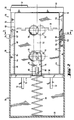
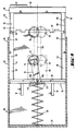
- the container comprises a plastic housing 10 in a rectangular shape;
- the top and bottom sides can be provided in a manner known per se with complementary stack projections or depressions in order to form blocks, composed of containers of the same type.
- the housing base is provided with two longitudinal grooves or slots 12 parallel to one another.
- a slide 14 is slidably guided between an inner end position and an outer end position. It comprises a guide part 16 and a front wall assembly 18 which is articulated to the guide part by means of a hinge 20 which lies approximately in the plane of the guide part bottom 22 and the bottom 24 of the front wall assembly.
- the guide part On the side facing the housing base, the guide part has molded-on lugs 26 which engage in the slots 12 of the housing base and form a definite stroke when the outer slide end position runs onto the outer slot end.
- a compression spring 29 is clamped between the housing rear wall 28 and the guide part rear wall 30 and presses the slide into the outer end position. If the slide is inserted, it locks by means of a bolt 32 in a recess 34 in the housing side wall 36; the bolt can be released by pressing a button 37.
- This locking mechanism is embedded in a cavity of the front wall 40 and forms no object of the present invention, so that a detailed description can be omitted. The same applies to a probe arm 42, which scans the occupancy of the container and actuates a corresponding indicator.
- the partial guide base 22 is stiffened by ribs 43 facing the housing base, and the same applies to the base of the front wall assembly.
- Guide and stiffening ribs 46 also extend outward from the side walls 44 of the guide part. In this way, cavities are delimited on both sides, in one of which a spring arrangement is accommodated, which prestresses the front wall assembly into the folded position shown in FIG. 1, in which a front end of an inserted cassette 48 can be freely grasped.
- the spring assembly comprises a leg spring 50 which sits with its wrap on a pin 52 formed on the guide part, one arm of which is supported on an abutment 54 also formed on the guide part and the other arm engages behind a web 56 attached to the underside of the front wall assembly.
- the folded-down position of the front wall assembly is defined by a stop 60 on the side walls 44 of the guide part, against which an arm 62 comes to rest, which extends from the front wall assembly beyond the hinge.
- a stop 60 on the side walls 44 of the guide part, against which an arm 62 comes to rest, which extends from the front wall assembly beyond the hinge.
- the pin 52 has an outer flange 53 which prevents the spring coil from falling down; so that the arm 62 can pass the pin, this flange is only formed at approximately 180 ° of the pin circumference.
- an inserted cassette 48 is positioned laterally from the side walls 44. At the bottom it rests on the guide part base 22, and from above it is positioned by ribs 47 formed on the inside of the top wall 45 of the housing.
- the side walls 44 of the guide part are chamfered at 64 and 66.
- the container described so far is functional. However, it is improved in terms of handling according to the invention.
- the slide would be ejected and the cassette would be catapulted out if it were not braked by hand.
- the storage position of the cassette is defined by the rear wall of the guide part, but an inserted cassette could move out again unnoticed, for example when the container is used in a moving vehicle, and when the user folds up the front wall assembly, it collides with it the cassette.
- the cassette is releasably locked in any possible accommodation orientation in the slide.
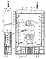
- Cassettes of the type in question here have two round recesses 70 which are arranged somewhat offset with respect to the plane of symmetry 72 extending in the direction of slide movement; As can be seen in FIG. 2, the projections of the depressions overlap over an angular range of approximately 60 °.
- locking cams 74 protrude from the bottom and the top side of the slide. They are formed on the free arms 76 of a sheet metal bracket 78, for example pressed out without cutting.
- the sheet metal bracket made of resilient material is snapped onto the rear wall 30 of the guide part by being pushed on from behind, with locking tongues 80 being deflected, which then spring back in front of the inside of the rear wall 30 and secure the seat of the angle 78.
- the free ends of the angle arms 76 are bent slightly outwards to prevent a collision with a cassette when it is inserted.
- the deck-side arm 76 is located between the ribs 47 on the housing top wall; the arm on the bottom lies in a recess 82 in the guide base 22.
- the cassette 48 is inserted so that the inner recess 70 is located above, so that the upper locking cam 74 engages, which is therefore not visible in Fig. 1.
- the lower cam 74 resiliently abuts the broad side of the cassette. It can be seen that the cassette can be inserted and locked in any orientation.
- the container basically has the same structure, so that only the deviations from FIGS. 1 to 3 need to be explained.
- an angle 84 made of plastic onto which locking cams 86 with a double circular segment-shaped outline (hatched in FIG. 4) are molded.
- the cams 86 have a run-in slope 88 with a gentle incline and a locking slope 90 of greater steepness. It is important that the plastic material of the angle is only elastically deformed for a short time, otherwise it would be deformed by cold flow. Therefore, the distance between the arms, measured between the two locking cams 86, is just as large as the dimension "D" from the base of the cassette 48 to the bottom of the recess 70, so that the angle is only briefly spread when the cassette is inserted or removed . On the other hand, since the position of the cassette as in the embodiment according to FIGS.
- the angle 84 is mounted so that it is a Can perform pivoting movement according to a locking cam height.
- the guide part base 22 is extended beyond the rear wall 30, and the angle 84 is fixed at 92 by means of rivet dies which were molded onto the base extension when the guide part was sprayed. This gives sufficient flexibility for the purposes explained above.
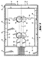
- a sheet metal bracket 100 with four resiliently deflectable arms 102 is riveted to the slide rear wall 30; each arm has an angled shape in the form of a cam at its free end.
- a recess 70 faces one of the cams in order to lock the cassette.
- FIGS. 9 and 10 a clamp similar to that in FIG. 1 is provided.
- the clip is not snapped onto the slide rear wall 30, but instead has an elongated hole 106 which is plugged onto a pin 108 formed on the rear wall of the slide. If there is no cassette in the slide, the spring 29 acts on the bracket base and presses it into abutment on the rear side of the slide rear wall. The clip takes up a search position in the longitudinal plane of symmetry 110 of the slide (FIG. 10).
- the locking members in the variant according to FIGS. 11 and 12 are constructed in a similar way, although no elongated hole is provided, and the return springs which bring the clip back into the search position are molded as arms 114 onto the clip itself.
- the cams 74 are formed on wire springs 76; they can therefore apply their restoring force to the search position themselves.
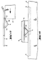
- FIG. 15 shows a greatly enlarged profile of a locking cam 74, seen transversely to the direction of insertion.
- a gently rising wedge surface 120 on which the edge 122 of the cassette strikes, and a steep locking wedge surface 124;
- the flanks 126 of the locking cam have the same steepness, viewed in the insertion direction according to FIG. 16.
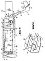
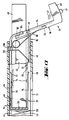
- FIG. 17 shows an advantageous modification of the container according to FIG. 1.
- the spring 50 does not sit with its winding on a pin, but this is freely movable in the cavity between the slide and the housing. Furthermore, the spring also has a loop 130 which - when the slide opens in the removal position - is shifted into a housing opening 132. The slide is thus blocked in the removal position, and the slide is only released for insertion when the spring loop is pulled back again by folding up the front wall assembly, by pressing the stop arm 134 on the spring.
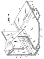
- FIG. 18 shows in perspective and broken away a detail of a variant which can be used in the exemplary embodiments according to FIG. 1 or 17.
- the articulated slide is biased by the spring 50 in such a way that the frictional conditions can become disruptive when extended from the housing, and all the more so if the extended spring 29 is relatively soft for the purpose of greater comfort when the slide is inserted.
- the frictional conditions become more favorable if the free end of the lever arm 62 is guided under a rib 15 which is integrally formed on the housing side wall 36 on one or both sides of the slide.
- the rib ends at the point where the lever arm should be able to fold up in order to fold the front wall assembly into the removal position.
- An entry slope 17 on the rib and a corresponding counter slope 19 on the lever arm 62 prevent the lever arm from hitting the free end of the rib.
Landscapes
- Packaging Of Annular Or Rod-Shaped Articles, Wearing Apparel, Cassettes, Or The Like (AREA)
- Automatic Tape Cassette Changers (AREA)
Applications Claiming Priority (2)
| Application Number | Priority Date | Filing Date | Title |
|---|---|---|---|
| DE3743481 | 1987-12-22 | ||
| DE3743481 | 1987-12-22 |
Publications (2)
| Publication Number | Publication Date |
|---|---|
| EP0321937A2 true EP0321937A2 (fr) | 1989-06-28 |
| EP0321937A3 EP0321937A3 (fr) | 1990-03-14 |
Family
ID=6343229
Family Applications (1)
| Application Number | Title | Priority Date | Filing Date |
|---|---|---|---|
| EP88121346A Withdrawn EP0321937A3 (fr) | 1987-12-22 | 1988-12-21 | Réceptacle pour emmagasiner des cassettes à bande magnétique |
Country Status (3)
| Country | Link |
|---|---|
| US (1) | US4875584A (fr) |
| EP (1) | EP0321937A3 (fr) |
| JP (1) | JPH01294475A (fr) |
Cited By (3)
| Publication number | Priority date | Publication date | Assignee | Title |
|---|---|---|---|---|
| EP0490049A3 (en) * | 1990-12-14 | 1992-08-12 | Fischerwerke Artur Fischer Gmbh & Co. Kg | Holder for magnetic tape cassettes |
| US5303993A (en) * | 1991-10-22 | 1994-04-19 | Artur Fischer Gmbh & Co. Kg. | Container for a magnetic tape cassette |
| EP0654788A1 (fr) * | 1993-11-19 | 1995-05-24 | fischerwerke Artur Fischer GmbH & Co. KG | Boîte pour cassette à bande magnétique |
Families Citing this family (15)
| Publication number | Priority date | Publication date | Assignee | Title |
|---|---|---|---|---|
| JPH0525006Y2 (fr) * | 1987-12-18 | 1993-06-24 | ||
| EP0384356A1 (fr) * | 1989-02-20 | 1990-08-29 | TDK Corporation | Cassettes à bande magnétique |
| DE4101002A1 (de) * | 1990-01-16 | 1991-07-18 | Toyoda Gosei Kk | Kassetten oder compakt-disk halter |
| US5038932A (en) * | 1990-01-30 | 1991-08-13 | Shwan Sheu | Cassette and video tape holder |
| DE4020163A1 (de) * | 1990-06-25 | 1992-01-02 | Fischer Artur Werke Gmbh | Behaelter fuer magnetbandkassetten |
| DE4135324A1 (de) * | 1991-10-25 | 1993-04-29 | Fischer Artur Werke Gmbh | Aufbewahrungseinrichtung fuer aufzeichnungstraeger |
| DE4219232A1 (de) * | 1992-06-12 | 1993-12-16 | Fischer Artur Werke Gmbh | Vorrichtung zur Aufbewahrung von Magnetbandkassetten |
| DE4219233A1 (de) * | 1992-06-12 | 1993-12-16 | Fischer Artur Werke Gmbh | Vorrichtung zur Aufbewahrung von Magnetbandkassetten |
| DE4324266A1 (de) * | 1993-07-20 | 1995-01-26 | Fischer Artur Werke Gmbh | Kassettenhalterung mit Klemmeinrichtung |
| US5549375A (en) * | 1994-11-14 | 1996-08-27 | Pagliaccio; Joseph A. | Computer storage drawer system |
| NO315314B1 (no) * | 2001-10-12 | 2003-08-18 | Smartbox As | Anordning ved forseglbart futteral |
| JP2005212899A (ja) * | 2004-02-02 | 2005-08-11 | Nifco Inc | 収納ボックス |
| US7597568B1 (en) * | 2008-05-29 | 2009-10-06 | Wistron Corp. | Electronic device and dust-proof mechanism thereof |
| ITTO20080436A1 (it) * | 2008-06-06 | 2009-12-07 | Itw Ind Components S R L Co N | Dispositivo di supporto regolabile in altezza per un elemento interno di appoggio di un elettrodomestico, quali un cestello lavastoviglie o un piano frigo |
| US9061827B1 (en) * | 2014-07-24 | 2015-06-23 | Kathleen Brennan | Pet waste container |
Family Cites Families (15)
| Publication number | Priority date | Publication date | Assignee | Title |
|---|---|---|---|---|
| FR2306498A1 (fr) * | 1975-04-03 | 1976-10-29 | Sony Corp | Coffret de conservation d'une cassette magnetique |
| US4184594A (en) * | 1978-12-22 | 1980-01-22 | Hehn Bruce A | Video cassette storage container |
| US4275943A (en) * | 1980-03-31 | 1981-06-30 | Shape Inc. | Container for a cassette |
| JPS609182Y2 (ja) * | 1981-06-18 | 1985-04-02 | アルファレコ−ド株式会社 | カセツトテ−プケ−スマガジン |
| EP0223940A1 (fr) * | 1982-01-20 | 1987-06-03 | idn inventions and development of novelties ag | Boîte pour le stockage de cassettes de bandes magnétiques ou autres supports d'enregistrement |
| DE3215721A1 (de) * | 1982-04-28 | 1983-11-03 | IDN Inventions and Development of Novelties AG, 7002 Chur | Magnetbandkassettenbehaelter |
| DE3247796A1 (de) * | 1982-12-23 | 1984-07-19 | IDN Inventions and Development of Novelties AG, Chur | Aufbewahrungsvorrichtung fuer scheibenfoermige aufzeichnungstraeger |
| EP0119320B1 (fr) * | 1983-01-15 | 1987-03-18 | idn inventions and development of novelties ag | Boîte pour le rangement de supports d'informations |
| EP0134279A1 (fr) * | 1983-08-29 | 1985-03-20 | idn inventions and development of novelties ag | Boîtier de stockage pour des cassettes de bande magnétique |
| DE8416751U1 (de) * | 1984-06-01 | 1985-09-26 | IDN Inventions and Development of Novelties AG, Chur | Vorrichtung zum Aufbewahren von Aufzeichnungsträgern, insbesondere zum Einbau in Kraftfahrzeuge |
| SE444620B (sv) * | 1984-09-21 | 1986-04-21 | Frodelius Jan Erik | Forvaringsanordning for band- eller skivformiga registreringsberare |
| US4632248A (en) * | 1985-07-29 | 1986-12-30 | Hsu Feng Mei | Sound/video-recording tape storing device |
| EP0215965B1 (fr) * | 1985-09-11 | 1988-05-11 | Herbert Richter, Metallwaren-Apparatebau GmbH & Co. | Boîte de rangement pour cassettes de bande d'enregistrement de son |
| DE3544054A1 (de) * | 1985-12-13 | 1987-06-19 | Idn Invention Dev Novelties | Aufbewahrungsbehaelter fuer aufzeichnungstraeger |
| JPS6355082A (ja) * | 1986-04-18 | 1988-03-09 | 瀬川 朝史 | カセツトケ−ス |
-
1988
- 1988-12-21 US US07/287,874 patent/US4875584A/en not_active Expired - Fee Related
- 1988-12-21 EP EP88121346A patent/EP0321937A3/fr not_active Withdrawn
- 1988-12-22 JP JP63325674A patent/JPH01294475A/ja active Pending
Cited By (4)
| Publication number | Priority date | Publication date | Assignee | Title |
|---|---|---|---|---|
| EP0490049A3 (en) * | 1990-12-14 | 1992-08-12 | Fischerwerke Artur Fischer Gmbh & Co. Kg | Holder for magnetic tape cassettes |
| US5215212A (en) * | 1990-12-14 | 1993-06-01 | Fischerwerke Artur Fischer Gmbh & Co. Kg | Container for magnetic tape cassettes |
| US5303993A (en) * | 1991-10-22 | 1994-04-19 | Artur Fischer Gmbh & Co. Kg. | Container for a magnetic tape cassette |
| EP0654788A1 (fr) * | 1993-11-19 | 1995-05-24 | fischerwerke Artur Fischer GmbH & Co. KG | Boîte pour cassette à bande magnétique |
Also Published As
| Publication number | Publication date |
|---|---|
| JPH01294475A (ja) | 1989-11-28 |
| EP0321937A3 (fr) | 1990-03-14 |
| US4875584A (en) | 1989-10-24 |
Similar Documents
| Publication | Publication Date | Title |
|---|---|---|
| EP0321937A2 (fr) | Réceptacle pour emmagasiner des cassettes à bande magnétique | |
| EP0668187B1 (fr) | Rideau écran pour break | |
| DE68912580T2 (de) | Schloss für Sicherheitsgurte. | |
| EP0163221B1 (fr) | Dispositif pour conserver des supports d'enregistrement, en particulier pour l'installation dans des véhicules à moteur | |
| DE2729151C2 (de) | Sicherheitsgurtverschluß | |
| AT6732U9 (de) | Selbstfärbestempel mit oberschlagfärbung sowie farbkissen-behälter hiefür | |
| DE2427103C3 (fr) | ||
| DE2521371A1 (de) | Behaelter zur aufnahme einer standard-magnetbandkassette | |
| AT412772B (de) | Selbstfärbe-handstempel | |
| DE2427109B2 (fr) | ||
| DE69709935T2 (de) | Sicherheitsschnalleanordnung für behälter mit deckel | |
| DE19603657A1 (de) | Sicherheitszubehör für Fahrzeuge | |
| EP1091880A1 (fr) | Contenant de transport presentant une unite de raccordement pour relier de maniere liberable des parois laterales | |
| EP0139164B1 (fr) | Boîtier de stockage pour des cassettes compactes | |
| DE3422692C2 (fr) | ||
| WO2014113832A1 (fr) | Tampon auto-encreur | |
| EP0205618B1 (fr) | Recipient pour disques compacts | |
| EP0385063B1 (fr) | Boîtier pour emmagasiner une cassette avec un support d'enregistrement en forme de bande | |
| EP0190180B1 (fr) | Dispositif pour le stockage de supports d'enregistrement plats | |
| EP0134278A1 (fr) | Boîtier à verrou pour emmagasiner des porteurs d'enregistrement | |
| EP0728106A1 (fr) | Conteneur de transport et de stockage | |
| DE3802008A1 (de) | Magnetbandkassettenbehaelter | |
| DE3324850C2 (fr) | ||
| DE2621248A1 (de) | Behaelter | |
| EP0113806A1 (fr) | Récipient pour cassettes à bande magnétique |
Legal Events
| Date | Code | Title | Description |
|---|---|---|---|
| PUAI | Public reference made under article 153(3) epc to a published international application that has entered the european phase |
Free format text: ORIGINAL CODE: 0009012 |
|
| AK | Designated contracting states |
Kind code of ref document: A2 Designated state(s): DE FR GB IT |
|
| PUAL | Search report despatched |
Free format text: ORIGINAL CODE: 0009013 |
|
| 17P | Request for examination filed |
Effective date: 19900105 |
|
| AK | Designated contracting states |
Kind code of ref document: A3 Designated state(s): DE FR GB IT |
|
| 17Q | First examination report despatched |
Effective date: 19920214 |
|
| STAA | Information on the status of an ep patent application or granted ep patent |
Free format text: STATUS: THE APPLICATION IS DEEMED TO BE WITHDRAWN |
|
| 18D | Application deemed to be withdrawn |
Effective date: 19920625 |