EP0322073A1 - Rasoir à sec avec système de transmission pour couteaux mobiles - Google Patents
Rasoir à sec avec système de transmission pour couteaux mobiles Download PDFInfo
- Publication number
- EP0322073A1 EP0322073A1 EP88202961A EP88202961A EP0322073A1 EP 0322073 A1 EP0322073 A1 EP 0322073A1 EP 88202961 A EP88202961 A EP 88202961A EP 88202961 A EP88202961 A EP 88202961A EP 0322073 A1 EP0322073 A1 EP 0322073A1
- Authority
- EP
- European Patent Office
- Prior art keywords
- knife
- working plane
- dry shaving
- rotary
- gear
- Prior art date
- Legal status (The legal status is an assumption and is not a legal conclusion. Google has not performed a legal analysis and makes no representation as to the accuracy of the status listed.)
- Withdrawn
Links
- 230000005540 biological transmission Effects 0.000 title claims description 5
- 210000004209 hair Anatomy 0.000 claims abstract description 14
- 230000010355 oscillation Effects 0.000 claims abstract description 4
- 230000001360 synchronised effect Effects 0.000 claims description 12
- 241000446313 Lamella Species 0.000 claims description 10
- 230000000712 assembly Effects 0.000 claims 1
- 238000000429 assembly Methods 0.000 claims 1
- 239000011888 foil Substances 0.000 abstract description 12
- XEEYBQQBJWHFJM-UHFFFAOYSA-N Iron Chemical compound [Fe] XEEYBQQBJWHFJM-UHFFFAOYSA-N 0.000 description 8
- 230000002349 favourable effect Effects 0.000 description 4
- 229910052742 iron Inorganic materials 0.000 description 4
- 230000005284 excitation Effects 0.000 description 2
- 230000033764 rhythmic process Effects 0.000 description 2
- 238000005452 bending Methods 0.000 description 1
- 230000034303 cell budding Effects 0.000 description 1
- 238000010276 construction Methods 0.000 description 1
- 230000000694 effects Effects 0.000 description 1
- 238000011179 visual inspection Methods 0.000 description 1
Images


Classifications
-
- B—PERFORMING OPERATIONS; TRANSPORTING
- B26—HAND CUTTING TOOLS; CUTTING; SEVERING
- B26B—HAND-HELD CUTTING TOOLS NOT OTHERWISE PROVIDED FOR
- B26B19/00—Clippers or shavers operating with a plurality of cutting edges, e.g. hair clippers, dry shavers
- B26B19/26—Clippers or shavers operating with a plurality of cutting edges, e.g. hair clippers, dry shavers of the type performing different methods of operation simultaneously, e.g. reciprocating and oscillating; of the type having two or more heads of differing mode of operation
- B26B19/265—Clippers or shavers operating with a plurality of cutting edges, e.g. hair clippers, dry shavers of the type performing different methods of operation simultaneously, e.g. reciprocating and oscillating; of the type having two or more heads of differing mode of operation of the type having two or more heads of differing mode of operation
Definitions
- the invention relates to a dry shaving device with a device for driving movable lower knife parts, which are set up together with fixed upper knife parts for cutting off body hair.
- the neck area is a problem area for many users of vibration dry shavers.
- the whiskers grow out of the skin in very different directions.
- the exit angle is sometimes very small, which means that the hair comes out very flat. If the hair is not cut by the vibrating knife arrangement during a first and in particular regular shave or overlooked, they continue to grow and can bend back to the surface of the skin.
- Vibratory shavers known from DE-PS 34 04 297 work with a shaving foil and a bottom knife moved back and forth under this shaving foil. But shaving foil razors are also known in which the lower knife rotates under a shaving foil. The shear effect is essentially the same, also with regard to the overlong problem hair. From DE-PS 803 640 it is known to have a foil shaving head with a clamped shaving foil rotating bottom knife to combine with a shaving head with a slotted shaving cap and rotating single, ground shaving knives below. The shaving performance of such a combination is unsatisfactory. In addition, the overall shaving head is too complicated.
- Such a dry shaving device is able, apart from shaving a full beard or budding full beard, to achieve a perfect shave with regular shaving even in longer daily cycles.
- the vibration knife arrangement of tried and tested design with domed clamped shaving foil and the lower knife pressed into this curvature allows a perfect shave with good results with regular shaving, especially during the day, except in the problem areas.
- the rotary knife arrangement with the upper blade section shaves as a separate and independently working system in the problem areas, such as on the neck or chin area, longer and in particular against the skin surface hair even without using a well-lit mirror or skin surface.
- the dry shaver combines the favorable properties of a vibrating shaver with the favorable properties of a rotary shaver with lamella shaving heads. It is not necessary for the rotary shaving head to bring the shave to a smooth finish.
- the force transmission of one of the knife arrangements takes place via a deflection gear, the deflection gear being a bevel gear. In this way it is possible to achieve an ergonomically favorable and particularly appealing design of the device.
- Such a bevel gear transmission thus also permits a rotary knife arrangement on the narrow side of the device, again in separate working planes, but here also quite close to the vibration knife arrangement. When using the device, it only needs to be rotated between these two working levels.
- the eccentric gear consists of a sliding block which is moved back and forth by the eccentric which is arranged on the motor shaft.
- the working height of the eccentric gear can be greatly reduced.
- the electric motor is a two-pole single-phase synchronous motor with a permanent magnetic rotor.
- the use of a single-phase synchronous motor with its rotor shaft profile perpendicular to the wide plane of the device enables the rocker arm gear to work in a wide plane of the device, while the rotary drive can be led directly out of the broad side of the device.
- the rotary knife part with the interposition of a gear, a rotational speed of 1800 to 3000 rpm at 50 Hz mains frequency (2160 to 3600 rpm at 60 Hz mains frequency) and the vibration meter by means of the eccentric or cam gear experience an oscillation frequency of 100 Hz (120 Hz).
- a single-phase synchronous motor rotates at 3000 or 3600 rpm via the network
- a double cam on the rotor shaft converts this rotational speed into a vibration frequency of 100 or 120 Hz via the rocker arm drive.
- the rotational speed is immediately transferred to the rotating rotary lower part, it rotates at a rotational speed of approx. 3000 or 3600 rpm.
- the rotational speed of the rotary lower knife in other favorable areas such.
- the device is provided with a rechargeable storage battery and solar cells are provided with which the storage battery can be recharged.
- a storage battery as is already frequently used today, and additional solar cells, operation independent of a mains connection is possible within wide limits.
- the lamellar upper knife part has such a web thickness that the rotary shave works particularly gently on the skin.
- a slat thickness between 0.1 mm and 0.5 mm is particularly suitable.
- the rotary lower knife is symmetrically shaped with a radial lamella course of the upper knife and the direction of rotation of the motor is arbitrary, the drive motor being a single-phase synchronous motor without a backstop.
- the structure is less complex.
- the drive of a dry shaving device 1, the housing 2 of which is only indicated, is carried out by means of a two-pole single-phase synchronous motor 3.
- the single-phase synchronous motor 3 has a U-shaped stator iron 4 and is pushed onto the iron legs 5 Excitation coils 6.
- a permanent magnetic rotor 9 is rotatably mounted about a rotor axis 10 which runs perpendicular to a wide plane 25 of the device.
- the motor works with a backstop (not shown) for one-way operation.
- An eccentric 11 is flanged onto the rotor axis 10 and can rotate in a slot 12 of a sliding block 13.
- the sliding block 13 is guided in guides 14.
- a transmission lever 15 is provided, which can move a vibrating under-knife part 17 in the direction of a double arrow 18 back and forth via driver 16.
- the lower knife 17 works together with a domed film upper knife 19 in a first working plane A.
- Fig. 1b From Fig. 1b it can be seen how the rotor shaft 10 is provided on the back of Fig. 1a with a driver cage 21 in which a driver bushing 22 is axially displaceable, but secured against rotation.
- the lamella webs 24a run at an angle to the radial 24b to the circumferential axis of the rotary lower knife 23.
- the rotary knife assembly 23, 24 works in a second working plane B.
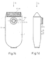
- FIGS. 1c and 1d show how the device looks with the drive arranged inside the device according to FIGS. 1a and 1b.
- the rotary knife arrangement 23/24 can shorten or completely shave hair in problem areas , while with the curved shaving foil knife arrangement 17, 19 it is possible to shave foil in unproblematic skin areas.
- the rotary knife arrangement is located on the broad side 2b parallel to a wide plane 25 of the device.
- the single-phase synchronous motor 3 with a backstop (not shown) is constructed as in the exemplary embodiment according to FIG. 1 and consists of a U-shaped stator iron 4 with excitation coils 6 pushed onto its legs 5.
- Stator poles 8 are located between the free leg ends 7 of the stator iron, between which can rotate a permanent magnetic rotor 9 with its axis 10.
- a double cam 11 is flanged onto the rotor axis 10.
- This double cam 11 works with a rocker arm drive 27.
- the rocker arm drive consists of a double-armed lever with a first lever arm 28 and a second lever arm 29.
- the double-armed lever 28/29 is mounted so that it can swing about a bearing 30.
- the first lever arm 28 carries a pressure roller 31 which can roll in a pressure bearing 32. Furthermore, the first lever arm 28 is pressed by means of a pressure spring 33 with its pressure roller 31 against the double cam 11. Further details of this rocker arm converter can be found in DE-PS 34 04 297.
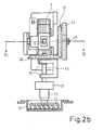
- a rotating knife arrangement is provided.
- This rotary knife arrangement is driven by a gear 43 flanged onto the rotor axis 10.
- This gear 43 meshes with a further gear 44.
- This gear 44 is firmly connected to a bevel gear 37. Both are rotatably mounted on an axle stub 45 of the axis 30.
- the bevel gear 37 meshes with a further bevel gear 38.
- a shaft 40 this second bevel gear 38 is mounted in bearings 39.
- the shaft 40 drives the driver cage 21 and, via this, the driver bush 22, which engages in a rotary lower knife 23, which again cooperates with a cap-shaped lamellar upper knife 24 with an oblique slot.
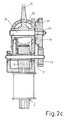
- the bevel gear construction which is difficult to see from FIG. 2a, can be seen from the view IIb and the section IIc according to FIG. 2a.
- the rotor shaft 10 first drives the gear 43 flanged onto it, which meshes with the gear 44.
- This gear 44 is fixed to a bevel gear 37, both of which are rotatably mounted on the stub shaft 45.
- the bevel gear 37 meshes with the bevel gear 38.
- the shaft 40 rotates the driving cage 21 and the driving bush 22, the rotating lower knife 23 in the rotating upper knife cap 24.
- the rotary knife speed can be adapted by this gear arrangement and second, the rotating knife arrangement is more tight the vibrating knife assembly can be moved closer.
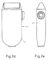
- 2d and 2e show how the rotary knife arrangement is arranged in a narrow side 2c of the device 47 in such a drive structure. This gives more freedom of maneuvering when using the rotary knife arrangement.
- the device can be operated with direct or alternating current depending on the type of motor used in the drive section.
- a Storage battery can be provided, which can be recharged via additional solar cells.
- the web thickness of the lamellae of the rotary upper knife is preferably between 0.1 mm and 0.5 mm, in order to enable work that is as gentle on the skin as possible.
- the preferred rotational speed of the rotary lower blade is 2000 rpm and the preferred oscillation frequency of the vibratory lower blade is 100 Hz, based on a rotor rotational speed of 3000 rpm.
- FIG. 3a shows a view of a symmetrical rotary lower knife 123 in a fixed rotary upper knife 124 designed as a cap, which is shown in section. It can be seen that the individual knives 123a of the rotary lower knife 123 run perpendicular to the lamella plane 125 and therefore have no preferred direction of rotation with regard to the cutting action and therefore cut equally well in both directions of rotation.
- FIG. 3b shows a top view of the symmetrically shaped rotary knife arrangement according to FIG. 3a.
- the slots 124a between the lamellae 124b of the rotary upper knife 124 run clearly in the radial direction.
- the individual knives 123a of the rotary lower knife 123 rotate under the slots 124a and lamellae 124b.
- 3a and 3b is used for two directions of rotation when a single-phase synchronous motor is used without a backstop.
- FIG. 4 shows an electric motor 52 fastened on a base plate 51 with a motor shaft 54 which extends axially along the motor center line 53.
- An eccentric disk 55 is fastened to this motor shaft 54 with an eccentric pin 56 which is eccentrically and axially parallel to it.
- the eccentric pin 56 engages in a driver 57 which moves the lower knife 17 back and forth below the shaving foil 19 of a shaving head in the direction of the double arrow 18.
- a bevel gear 58 which meshes with a bevel gear 38, is flanged onto the motor shaft 54.
- a shaft 40 of the bevel gear 38 is supported in bearings 39.
- the shaft 40 drives the driver cage 21 and, via this, the driver bush 22, which engages in a rotary lower knife 23, which again cooperates with a cap-shaped upper blade knife 24 with an oblique slot.
- FIG 4 also shows the first working plane A, in which the vibrating knife arrangement works, and the second working plane B, in which the second rotating knife arrangement works.
Landscapes
- Life Sciences & Earth Sciences (AREA)
- Forests & Forestry (AREA)
- Engineering & Computer Science (AREA)
- Mechanical Engineering (AREA)
- Dry Shavers And Clippers (AREA)
Applications Claiming Priority (2)
| Application Number | Priority Date | Filing Date | Title |
|---|---|---|---|
| DE3743736 | 1987-12-23 | ||
| DE19873743736 DE3743736A1 (de) | 1987-12-23 | 1987-12-23 | Trockenrasiergeraet mit einer vorrichtung zum antreiben von beweglichen untermesserteilen |
Publications (1)
| Publication Number | Publication Date |
|---|---|
| EP0322073A1 true EP0322073A1 (fr) | 1989-06-28 |
Family
ID=6343380
Family Applications (1)
| Application Number | Title | Priority Date | Filing Date |
|---|---|---|---|
| EP88202961A Withdrawn EP0322073A1 (fr) | 1987-12-23 | 1988-12-19 | Rasoir à sec avec système de transmission pour couteaux mobiles |
Country Status (3)
| Country | Link |
|---|---|
| EP (1) | EP0322073A1 (fr) |
| JP (1) | JPH01204691A (fr) |
| DE (1) | DE3743736A1 (fr) |
Cited By (2)
| Publication number | Priority date | Publication date | Assignee | Title |
|---|---|---|---|---|
| CN102303253A (zh) * | 2011-08-20 | 2012-01-04 | 常州朗博汽车零部件有限公司 | 骨架密封圈修边机双刀夹持装置 |
| JP2021065435A (ja) * | 2019-10-24 | 2021-04-30 | マクセルイズミ株式会社 | ロータリー式電気かみそり |
Families Citing this family (1)
| Publication number | Priority date | Publication date | Assignee | Title |
|---|---|---|---|---|
| RU2644105C1 (ru) * | 2015-02-03 | 2018-02-07 | Конинклейке Филипс Н.В. | Устройство для удаления ворса с поверхности изделия из ткани |
Citations (4)
| Publication number | Priority date | Publication date | Assignee | Title |
|---|---|---|---|---|
| US30857A (en) * | 1860-12-04 | 1860-12-04 | Superheating steam fob locomotive-engines | |
| FR1080551A (fr) * | 1953-02-21 | 1954-12-10 | Rasoir automatique mixte | |
| EP0116143A1 (fr) * | 1982-12-08 | 1984-08-22 | De Wit-Paschek, Diane Rosette Annie | Rasoir électrique |
| EP0152143A2 (fr) * | 1984-02-08 | 1985-08-21 | Philips Patentverwaltung GmbH | Système d'entraînement à mouvement de "va-et-vient" pour rasoir électrique à feuille perforée équipé d'un moteur synchrone mono-phase |
-
1987
- 1987-12-23 DE DE19873743736 patent/DE3743736A1/de not_active Withdrawn
-
1988
- 1988-12-19 EP EP88202961A patent/EP0322073A1/fr not_active Withdrawn
- 1988-12-20 JP JP31969788A patent/JPH01204691A/ja active Pending
Patent Citations (4)
| Publication number | Priority date | Publication date | Assignee | Title |
|---|---|---|---|---|
| US30857A (en) * | 1860-12-04 | 1860-12-04 | Superheating steam fob locomotive-engines | |
| FR1080551A (fr) * | 1953-02-21 | 1954-12-10 | Rasoir automatique mixte | |
| EP0116143A1 (fr) * | 1982-12-08 | 1984-08-22 | De Wit-Paschek, Diane Rosette Annie | Rasoir électrique |
| EP0152143A2 (fr) * | 1984-02-08 | 1985-08-21 | Philips Patentverwaltung GmbH | Système d'entraînement à mouvement de "va-et-vient" pour rasoir électrique à feuille perforée équipé d'un moteur synchrone mono-phase |
Cited By (3)
| Publication number | Priority date | Publication date | Assignee | Title |
|---|---|---|---|---|
| CN102303253A (zh) * | 2011-08-20 | 2012-01-04 | 常州朗博汽车零部件有限公司 | 骨架密封圈修边机双刀夹持装置 |
| CN102303253B (zh) * | 2011-08-20 | 2016-03-09 | 常州朗博密封科技股份有限公司 | 骨架密封圈修边机双刀夹持装置 |
| JP2021065435A (ja) * | 2019-10-24 | 2021-04-30 | マクセルイズミ株式会社 | ロータリー式電気かみそり |
Also Published As
| Publication number | Publication date |
|---|---|
| DE3743736A1 (de) | 1989-07-13 |
| JPH01204691A (ja) | 1989-08-17 |
Similar Documents
| Publication | Publication Date | Title |
|---|---|---|
| DE19736776C2 (de) | Trockenrasierapparat | |
| DE60314376T2 (de) | Haarentfernungsgerät | |
| DE4026142C2 (fr) | ||
| DE69703658T2 (de) | Trockenrasierer | |
| DE69224761T2 (de) | Trockenrasiergerät | |
| DE69703844T2 (de) | Trockenrasierer | |
| DE10330205A1 (de) | Elektrisches Haarschneidegerät | |
| EP1161325A1 (fr) | Rasoir electrique | |
| WO2007033730A1 (fr) | Appareil pour eliminer des poils et des cheveux | |
| DE2114709A1 (fr) | ||
| DE202015009110U1 (de) | Haarschneidegerät | |
| DE69504163T2 (de) | Rasierapparat | |
| DE60108451T2 (de) | Elektrischer Rasierapparat | |
| CH639891A5 (de) | Rasiergeraet. | |
| EP0322073A1 (fr) | Rasoir à sec avec système de transmission pour couteaux mobiles | |
| DE837666C (de) | Schergeraet fuer Rasierschnitt | |
| DE1040937B (de) | Elektrischer Rasierapparat | |
| DE2803513A1 (de) | Sicherheits-rasierapparat | |
| DE1225992B (de) | Trockenrasiergeraet mit einem Rasierkopf | |
| DE3310706C2 (fr) | ||
| EP0322072A1 (fr) | Tête rotative pour rasoir électrique à sec | |
| DE1086149B (de) | Trockenrasiergeraet mit zwei verschiedenen Schneidvorrichtungen | |
| DE60001093T2 (de) | Rasierkopf mit drehbarem haarmanipulator | |
| DE102004021503B3 (de) | Trockenrasierapparat oder Haarschneidemaschine mit einem als Distanzkamm ausgebildeten Aufsatz | |
| DE1553808A1 (de) | Elektrischer Trockenrasierapparat |
Legal Events
| Date | Code | Title | Description |
|---|---|---|---|
| PUAI | Public reference made under article 153(3) epc to a published international application that has entered the european phase |
Free format text: ORIGINAL CODE: 0009012 |
|
| AK | Designated contracting states |
Kind code of ref document: A1 Designated state(s): AT CH DE FR GB IT LI NL |
|
| STAA | Information on the status of an ep patent application or granted ep patent |
Free format text: STATUS: THE APPLICATION IS DEEMED TO BE WITHDRAWN |
|
| 18D | Application deemed to be withdrawn |
Effective date: 19891229 |