EP0322122A2 - Drucksensor - Google Patents
Drucksensor Download PDFInfo
- Publication number
- EP0322122A2 EP0322122A2 EP88311276A EP88311276A EP0322122A2 EP 0322122 A2 EP0322122 A2 EP 0322122A2 EP 88311276 A EP88311276 A EP 88311276A EP 88311276 A EP88311276 A EP 88311276A EP 0322122 A2 EP0322122 A2 EP 0322122A2
- Authority
- EP
- European Patent Office
- Prior art keywords
- chamber
- signal processing
- pressure sensor
- chambers
- wall
- Prior art date
- Legal status (The legal status is an assumption and is not a legal conclusion. Google has not performed a legal analysis and makes no representation as to the accuracy of the status listed.)
- Granted
Links
Images


Classifications
-
- G—PHYSICS
- G01—MEASURING; TESTING
- G01L—MEASURING FORCE, STRESS, TORQUE, WORK, MECHANICAL POWER, MECHANICAL EFFICIENCY, OR FLUID PRESSURE
- G01L19/00—Details of, or accessories for, apparatus for measuring steady or quasi-steady pressure of a fluent medium insofar as such details or accessories are not special to particular types of pressure gauges
- G01L19/14—Housings
- G01L19/147—Details about the mounting of the sensor to support or covering means
-
- G—PHYSICS
- G01—MEASURING; TESTING
- G01L—MEASURING FORCE, STRESS, TORQUE, WORK, MECHANICAL POWER, MECHANICAL EFFICIENCY, OR FLUID PRESSURE
- G01L19/00—Details of, or accessories for, apparatus for measuring steady or quasi-steady pressure of a fluent medium insofar as such details or accessories are not special to particular types of pressure gauges
- G01L19/0007—Fluidic connecting means
- G01L19/0038—Fluidic connecting means being part of the housing
-
- G—PHYSICS
- G01—MEASURING; TESTING
- G01L—MEASURING FORCE, STRESS, TORQUE, WORK, MECHANICAL POWER, MECHANICAL EFFICIENCY, OR FLUID PRESSURE
- G01L19/00—Details of, or accessories for, apparatus for measuring steady or quasi-steady pressure of a fluent medium insofar as such details or accessories are not special to particular types of pressure gauges
- G01L19/0061—Electrical connection means
- G01L19/0084—Electrical connection means to the outside of the housing
-
- G—PHYSICS
- G01—MEASURING; TESTING
- G01L—MEASURING FORCE, STRESS, TORQUE, WORK, MECHANICAL POWER, MECHANICAL EFFICIENCY, OR FLUID PRESSURE
- G01L19/00—Details of, or accessories for, apparatus for measuring steady or quasi-steady pressure of a fluent medium insofar as such details or accessories are not special to particular types of pressure gauges
- G01L19/04—Means for compensating for effects of changes of temperature, i.e. other than electric compensation
-
- G—PHYSICS
- G01—MEASURING; TESTING
- G01L—MEASURING FORCE, STRESS, TORQUE, WORK, MECHANICAL POWER, MECHANICAL EFFICIENCY, OR FLUID PRESSURE
- G01L19/00—Details of, or accessories for, apparatus for measuring steady or quasi-steady pressure of a fluent medium insofar as such details or accessories are not special to particular types of pressure gauges
- G01L19/14—Housings
-
- G—PHYSICS
- G01—MEASURING; TESTING
- G01L—MEASURING FORCE, STRESS, TORQUE, WORK, MECHANICAL POWER, MECHANICAL EFFICIENCY, OR FLUID PRESSURE
- G01L19/00—Details of, or accessories for, apparatus for measuring steady or quasi-steady pressure of a fluent medium insofar as such details or accessories are not special to particular types of pressure gauges
- G01L19/14—Housings
- G01L19/142—Multiple part housings
- G01L19/143—Two part housings
-
- G—PHYSICS
- G01—MEASURING; TESTING
- G01L—MEASURING FORCE, STRESS, TORQUE, WORK, MECHANICAL POWER, MECHANICAL EFFICIENCY, OR FLUID PRESSURE
- G01L19/00—Details of, or accessories for, apparatus for measuring steady or quasi-steady pressure of a fluent medium insofar as such details or accessories are not special to particular types of pressure gauges
- G01L19/14—Housings
- G01L19/148—Details about the circuit board integration, e.g. integrated with the diaphragm surface or encapsulation
-
- G—PHYSICS
- G01—MEASURING; TESTING
- G01L—MEASURING FORCE, STRESS, TORQUE, WORK, MECHANICAL POWER, MECHANICAL EFFICIENCY, OR FLUID PRESSURE
- G01L27/00—Testing or calibrating of apparatus for measuring fluid pressure
- G01L27/007—Malfunction diagnosis, i.e. diagnosing a sensor defect
-
- Y—GENERAL TAGGING OF NEW TECHNOLOGICAL DEVELOPMENTS; GENERAL TAGGING OF CROSS-SECTIONAL TECHNOLOGIES SPANNING OVER SEVERAL SECTIONS OF THE IPC; TECHNICAL SUBJECTS COVERED BY FORMER USPC CROSS-REFERENCE ART COLLECTIONS [XRACs] AND DIGESTS
- Y10—TECHNICAL SUBJECTS COVERED BY FORMER USPC
- Y10T—TECHNICAL SUBJECTS COVERED BY FORMER US CLASSIFICATION
- Y10T29/00—Metal working
- Y10T29/49—Method of mechanical manufacture
- Y10T29/49002—Electrical device making
- Y10T29/49082—Resistor making
- Y10T29/49103—Strain gauge making
Definitions
- This invention relates to pressure sensors of the type using separate pressure sensing and electrical signal processing elements, and particularly to the packaging and fabrication of such sensors.
- Pressure sensors are used in automotive vehicles for a variety of purposes, for example, sensing the vacuum pressure at the intake manifold of a vehicle engine.
- pressure sensor comprises a pressure sensing element, including a piezoresistive silicon semiconductor chip, and a separate semiconductor integrated circuit (IC) for receiving an electrical signal from the sensing element, processing the signal, and generating the output signal from the pressure sensor.
- the pressure sensing element is completely enclosed in its own sub-package which includes outwardly extending terminals permitting electrical access to the enclosed sensing element.
- the sub-package is entirely enclosed, in turn, in the main package of the pressure sensor.
- the main package includes a port which communicates directly with an opening in the pressure sensing element sub-package permitting exposure of the pressure sensing element to the pressure to be sensed.
- the signal processing IC is also mounted within the package main housing and electrically connected to the terminals of the pressure sensing element sub-package by wire bonds. Finally, wire bonds interconnect terminal portions of the signal processing IC to terminals of the main package.
- a pressure sensor in accordance with the present invention is characterised over the above mentioned prior art by the feature specified in the characterising portion of Claim 1.
- the present invention is directed to a pressure sensor comprising two chambers which are hermetically sealed one from the other with the first chamber containing a pressure sensing element and the second chamber containing a signal processing element. Electrical interconnections couple the two elements. A portion of the pressure sensor defines a port or opening which couples the first chamber to a pressure to be sensed.
- the pressure sensor further comprises a relatively high thermal conductivity member having a portion thereof that thermally contacts a substantial portion of the signal processing element and having another portion thereof that extends into the first chamber such that any temperature differential between the two chambers is moderated.
- the enclosure or package for the pressure sensor comprises two separate chambers which are hermetically sealed from one another.
- the pressure sensing element is disposed within one of the chambers and a port is coupled to that chamber to permit exposure of the sensing element to the pressure to be sensed.
- a signal processing element is disposed within the other chamber. Electrical interconnections between the two elements are by means of conductive leads which extend, in hermetic fit, through an inner wall separating the two chambers.
- thermally and electrically conductive members are provided for closely thermally coupling together the two chambers and the respective elements therein.
- One such member comprises one of the interconnecting electrical leads which is disposed along the bottom surface of the chamber containing the signal processing element.
- a bottom surface of the signal processing element is mounted directly on an enlarged portion of the the lead in good thermal relation therewith.
- the lead extends through the inner wall separating the chambers and directly into the chamber containing the pressure sensing element. Heat from the pressure sensing element chamber is thus conducted directly by the lead and into direct contact with the signal processing element.
- Another such thermally conducting member comprises a separate base portion (bottom closure member) of the package which is formed from a material, e.g., a metal, which is more highly thermally conductive than other portions of the package.
- This base portion forms the bottom wall of the pressure sensing element chamber and extends beneath the inner wall separating the two chambers and directly beneath, and in intimate thermal connection with the bottom wall forming the bottom of the other chamber. Heat from the pressure sensing chamber is thus transferred, via the bottom closure member, to the signal processing element chamber through the bottom wall thereof.
- the pressure sensor is designed to allow the chamber containing the pressure sensor element to be pressurized to a test pressure while the other chamber is left open such that the signal processing element can be tested and modified as desired.
- FIG. 1 With reference to Figures 1 and 2, there is shown a pressure sensor 10 (also denoted as a pressure sensor assembly 10) in accordance with this invention.
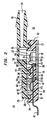
- Figure 2 shows a cross sectional view of Figure 1 along dashed line 2-2.
- the pressure sensor 10 comprises a three-part package which includes a main housing member 12, a top cover member 14, which includes a port member 16 and an air vent hole 81, and a bottom closure member 18.
- the main housing member 12 and the top cover member 14 are preferably made of a known thermoplastic resin
- the bottom closure member 18 is preferably formed of a high thermally conductive material, e.g., a metal such as aluminium, or a high thermally conductive ceramic.
- a tongue-in-groove joint is used, the tongue portion 26 of the joint ( Figure 2) being dependent from the top cover member 14, and the groove portion 28 being provided in the main housing member 12.
- a recess 27 is provided in the bottom surface of the main housing member 12 for receipt of the bottom closure member 18.
- the pressure sensor 10 contains two spaced-apart chambers 20 and 22.
- the package walls defining the chambers 20, 22 include an outer wall 29 of the main housing member 12 and an inner wall 30 bisecting the main housing member 12 and hermetically separating the two chambers 20 and 22.
- the groove portion 28 which forms part of the tongue-in-groove joint with the top cover member 18 (Figure 2), is formed in the top surfaces of the outer and inner walls 29 and 30.
- the inside wall of the groove portion 28 defines two wall or lip portions 31 and 33, the lip portion 31 forming part of the wall defining the chamber 22 and the lip portion 33 forming part of the wall defining the chamber 20.
- the lip portion 31 around the chamber 22 forms a cylinder which projects beyond the upper surface of other portions of the two walls 29 and 30.
- the upper end of the lip portion (or cylinder) 31 terminates in an annular surface 35 ( Figure 3). The purpose of these structural details is described hereinafter.
- a pressure sensing element 32 disposed within the chamber 22 is a pressure sensing element 32 of known type, e.g., a silicon semiconductor chip of the type described in the aforementioned Oakes article.
- the chamber 22 communicates with a port or opening 34 through the port member 16 for the admission of the pressure to be sensed by the pressure sensing element 32 disposed within the chamber 22.
- a semiconductor integrated circuit (IC) chip Disposed within the other chamber 20 is a semiconductor integrated circuit (IC) chip of known type referred to as a signal conditioning or processing element 36.
- the purpose of the signal processing element 36 is to receive an electrical signal from an electrical circuit (e.g., a Wheatstone bridge circuit -not shown) on the pressure sensing element 32 and process it (e.g., provide temperature compensation and signal amplification) to produce an output signal from the pressure sensor 10.
- an electrical circuit e.g., a Wheatstone bridge circuit -not shown
- process it e.g., provide temperature compensation and signal amplification
- a low wall 40 having sloped sides which extends parallel to the inner wall 30 separating the two chambers 20 and 22.
- This low wall 40 along with the outer wall 29 (which also has sloped sides within the chamber 20), defines a recess 42 (typically rectangular - see, also, Figure 3) within the chamber 20 for receipt of the signal processing element 36.
- the pressure sensing and signal processing elements 32 and 36 are interconnected to one another and to terminal leads of the pressure sensor 10 as follows.
- a number of conductive leads 46 through 50 Partially embedded within the material of the main housing member 12 are a number of conductive leads 46 through 50.
- various portions of each of the leads 46-50 are exposed within each of the two chambers 20 and 22.
- three of the leads 46, 47, and 48 extend outwardly from one end of the main housing member 12 and serve as exterior terminals for the pressure sensor 10.
- Other leads, not shown, can be provided extending from the other end of the main housing member to serve as means for mechanically supporting the pressure sensor, e.g., within a socket of known type, not shown.
- leads 46-50 are shown, partially in dashed lines where the leads are embedded within the main housing member 12, in Figure 1.
- these leads extend into the main housing member 12 and pass, still embedded wtihin the housing member material, on either side of the chamber 20.
- the two leads 46 and 48 then emerge ( Figure 1) within the chamber 20 in the space between the low wall 40 within the chamber 20 and the inner wall 30 separating the two chambers 20 and 22.
- the lead 46 continues through the inner wall 30 and emerges, exposed, within the chamber 22.
- the other lead 48 also continues into the inner wall 30 but terminates there.
- the third, central terminal lead 47 extends into the main housing member 12 and directly into the chamber 20 (see also Figure 3).
- the width of the lead 47 expands in an enlarged portion 47a thereof to completely cover the bottom surface of the recess 42.
- the edges of the enlarged portion 47a extend beneath the recess walls, hence the edges are shown in dashed lines in Figure 1).
- the lead 47 narrows in width, passes ( Figure 2) under the low wall 40, and becomes exposed again in the space between the low wall 40 and inner wall 30.
- the lead 47 then passes through the inner wall 30 and emerges within the chamber 22.
- the various leads which pass through the inner wall 30 follow a zigzag path for better utilization of the package space.
- leads 49 and 50 Two more leads 49 and 50 (see Figures 1 and 3) are provided. These leads 49, 50 start, exposed, on the bottom surface of the chamber 20 in the space between the low wall 40 and inner wall 30, pass through the inner wall 30, and emerge within the chamber 22.
- each of the leads 46, 47, 49, and 50 extends into the chamber 22.
- the spaces between the leads are filled with thin layers or webs 52 of the material of the main housing member 12.
- the combination of the continuous surface formed by the alternating leads and webs, and the dependent bar 55 forms a trough 61 ( Figure 2) which is preferably filled with a known protective or passivating substance 56 for hermetically sealing the exposed joints between the inner wall 30 and the emerging leads. This is known as "backside passivation" of the leads.
- a silicon adhesive can be used as a passivating substance.
- a trench 60 is provided through a bottom wall 64 of the chamber 20.
- the trench (trough) 60 is not shown in Figure 1.
- the trench 60 extends beneath the space between the low and inner walls 40 and 30 a distance sufficient to fully expose the undersides of all the leads 46-50 where they extend into (and thus form joints with) the inner wall 30.
- This trench 60 is also filled with the passivating substance 56.
- a function of the signal processing element 36 (within the chamber 20) is to process the electrical signal from the pressure sensing element 32. It is a known characteristic of such signal processing elements 36 that the output signal therefrom is a function (among other things) of the temperature differential between the signal processing and pressure sensing elements. However, the temperature of the gases admitted into the (pressure sensing) chamber 20 during use of the pressure sensor 10 is variable. This can give rise to a variable temperature differential between the pressure sensing and signal processing elements 32, 36 which, in turn, can cause errors in the output signal of the pressure sensor 10.
- means are provided for reducing any temperature differential between the signal processing and pressure sensing elements 36 and 32.
- a first means for reducing temperature differentials between pressure sensing and signal processing elements 32 and 36 comprises electrical lead 47 which enters chamber 20 and runs under signal processing element 36 and makes good thermal contact therewith.
- Lead 47 passes through inner wall 30 and enters chamber 22.
- Another bonding lead 54 is bonded by one end to lead 47 where it enters chamber 22 and is bonded by a second end to a bonding pad on a top surface of pressure sensing element 32.
- the physical shape of lead 47 and its location facilitates a good transfer of heat to signal processing element 36 from chamber 22 and pressure sensing element 32.
- lead 47 is essentially electrically isolated from the bottom of signal processing element 36 and a bonding lead 54 makes electrical contact between a bonding pad on a top surface of signal processing element 36 and a portion of lead 47. In some applications it is feasible that enlarged portion 47a of lead 47 could make both thermal and electrical contact to the bottom surface of signal processing element 36.
- a second means for reducing temperature differentials between pressure sensing and signal processing elements 32 and 36 comprises the various leads 46, 49, and 50 which extend between and into both chambers.
- a third means for reducing temperature differentials between pressure sensing and signal processing elements 32 and 36 comprises the bottom closure member 18 (Figure 2) which, as previously mentioned, is preferably made of a high thermal conductive material and which extends from beneath the chamber 22 to beneath the chamber 20.
- the bottom closure member 18 which conducts, with little temperature drop, heat energy from the chamber 22 to the bottom wall 64 of the chamber 20.
- the portion of the bottom wall 64, which directly overlies the bottom closure member 18, is of reduced thickness (by the thickness of the bottom closure member 18), and heat from the bottom closure member 18 is conducted through the bottom wall 64 to the enlarged portion 47a of the lead 47.
- This enlarged portion 47a which as previously described, underlies the entire bottom surface of the signal processing element 36 (see Figure 1), provides an excellent path for heat conduction to the signal processing element 36.
- the temperature differential between the pressure sensing and signal processing elements 32 and 36 should be approximately 5 degrees C.
- a temperature differential of up to approximately 15 degrees C. is useful. This is small enough so as not to introduce unacceptably high errors in the output readings from the pressure sensor 10.
- the main housing member 12 and the top cover member 14 are formed from a thermoplastic resin and are fabricated using known moulding techniques.
- the various leads are first formed as part of a stamped or etched sheet of metal held together by a peripheral frame. This sheet, known as a lead frame, is placed within a mould, and the thermoplastic resin is forced into the mould to form the main housing member 12 around the various leads.
- the frame peripheral members which are not embedded within the material of the main housing member 12, are broken away to electrically isolate the various leads 46-50 from one another.
- the remaining package part, i.e., the bottom closure member 18, is preferably formed by a stamping process.
- a pressure sensing element 32 of the type shown in the aforementioned Oakes article is used.
- the pressure sensing element 32 comprises a disc of semiconducting material, e.g., silicon, having a recess therein forming a pressure sensitive diaphragm.
- a simple Wheatstone bridge circuit is formed within the silicon disc by appropriate doping techniques, and terminal pads are provided on the disc by means of which electrical interconnections can be made thereto.
- the disc is electrostatically bonded to a block of borosilicate glass 83, for purposes of stress isolation, and the glass block, in turn, is mounted and glued to a top surface of the bottom closure member 18.
- Passivating substance 56 is then put into troughs 60 and 61 and then bottom closure member 18 is adhesively attached (i.e., glued) to main housing member 12 to close the bottom of chamber 22 and to form a hermetic seal. Additional amounts of passivating substance 56 are placed in recess 27. For the sake of simplicity the drawings do not show passivating substance 56 in recess 27.
- the signal processing element 36 is then glued in place within the recess 42 formed within the chamber 20. Proper positioning of the signal processing element 36 within the recess 42 is simplified by the sloped sides of the recess defining outer and low walls 29 and 40. Also, a known high thermal conductive adhesive is preferably used to provide an intimate and good thermal conducting interface between the bottom surface of the signal processing element 36 and the enlarged portion 47a at the bottom of the recess.
- the wire bonds 54 are then made between various terminal pads on each of the signal processing and pressure sensing elements 36, 32 and the exposed surface portions of the leads 46-50 in each of the respective chambers 20 and 22.
- a known protective coating 68 ( Figure 2) is then applied over the pressure sensing element 32 to protect it against any hostile environment, e.g., automotive engine gases, which it will encounter in use.
- the protective coating is also applied over the exposed surface portions of the leads 46-50 including the ends of the wire bonds 54 bonded thereto to protect against any hostile environment and to help hermetically seal chamber 22 where the electrical leads enter same from chamber 20.
- protective coating 68 is a long chain polymer.
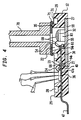
- a test pressure applying means known as a boot 70 ( Figure 4) is applied against the annular surface 35 of the (upwardly extending) lip portion 31 surrounding the chamber 22, and a test pressure or vacuum is applied to the chamber 22 via the boot.
- a rubber gasket 71 is provided at the end of the boot. Because the lip portion 31 extends higher than other wall portions of the main housing member 12, as previously described, the rubber gasket 71, when squeezed between the boot 70 and annular surface 35, is free to deform downwardly and around the lip portion. This, it is found, ensures an hermetic fit between the boot 70 and the chamber 22.
- the package With the boot 70 in place and a pressure applied to the chamber 22, the package is tested, using known procedures, for leaks between the two chambers 20 and 22. If there are no leaks, the next step, with the boot 70 in place and a known pressure applied to the pressure sensing element 32, is to measure the electrical parameters of the signal processing element 36. Then, as necessary, adjustments (i.e., the trimming of resistors) are made to the signal processing element 36 to adjust its parameters to provide a preselected output signal consistent with the test pressure.
- adjustments i.e., the trimming of resistors
- a feature of the package of this invention is that the provision of the two separate chambers 20 and 22 allows the enclosure of the chamber 22 by the boot 70 while leaving the chamber 20 and the signal processing element 36 therein fully uncovered.
- This allows unencumbered access to and direct contacting of the signal processing element 36 by means of electrical probes 72, or the like, for measuring the electrical parameters of the signal processing element 36. Then, using known techniques, these parameters are adjusted as necessary.
- different ones of the electrical probes 72 can be used to send currents through selected current paths for burning open these paths, thereby selectively altering the electrical characteristics of the element circuits.
- a laser beam can be used to burn open selective portions of the circuitry to make the desired adjustments.
- the boot 70 is removed and a protective coating 68 ( Figure 2) is applied over the signal processing element 36 and over the portions of the electrical leads 46-50 and wire bonds 54 where the electrical leads enter inner wall 30.
- the pressure sensor 10 is completed by the addition of the top cover member 14.
- the top cover member 14 is hermetically sealed to the main housing member 12 by means of an adhesive which is dispensed into the groove portion 28 surrounding the chambers 20 and 22.
- Air vent hole 81 in top cover member 14 serves to allow any air in the adhesive used in the portion of groove portion 28 surrounding chamber 20, which might escape into chamber 20, to be vented out. Thus helps eliminate any build up of pressure in chamber 20 which could cause a break in hermetic seal between chambers 20 and 22.
- bottom closure member 18 could extend further across the bottom of chamber 20 to further increase the thermal equalization desired between the signal processing and pressure sensing elements 36,32.
- outside geometry of pressure sensor 10 can readily be modified to permit use of pressure sensor 10 in different mounting arrangements.
- top cover member 14 can be replaced with two separate portions. The first portion would cover chamber 20 and the second portion would cover chamber 22.
- bottom closure member 18 can be of the same material as main housing member 12.
Landscapes
- Physics & Mathematics (AREA)
- General Physics & Mathematics (AREA)
- Chemical & Material Sciences (AREA)
- Analytical Chemistry (AREA)
- Health & Medical Sciences (AREA)
- Engineering & Computer Science (AREA)
- Biomedical Technology (AREA)
- Measuring Fluid Pressure (AREA)
Priority Applications (1)
| Application Number | Priority Date | Filing Date | Title |
|---|---|---|---|
| EP91203296A EP0480544B1 (de) | 1987-12-22 | 1988-11-29 | Methode zur Herstellung und zum Justierung eines Drucksensors |
Applications Claiming Priority (2)
| Application Number | Priority Date | Filing Date | Title |
|---|---|---|---|
| US07/136,579 US4850227A (en) | 1987-12-22 | 1987-12-22 | Pressure sensor and method of fabrication thereof |
| US136579 | 1987-12-22 |
Related Child Applications (3)
| Application Number | Title | Priority Date | Filing Date |
|---|---|---|---|
| EP91203296.8 Division-Into | 1988-11-29 | ||
| EP91203296A Division-Into EP0480544B1 (de) | 1987-12-22 | 1988-11-29 | Methode zur Herstellung und zum Justierung eines Drucksensors |
| EP91203296A Division EP0480544B1 (de) | 1987-12-22 | 1988-11-29 | Methode zur Herstellung und zum Justierung eines Drucksensors |
Publications (3)
| Publication Number | Publication Date |
|---|---|
| EP0322122A2 true EP0322122A2 (de) | 1989-06-28 |
| EP0322122A3 EP0322122A3 (de) | 1991-01-30 |
| EP0322122B1 EP0322122B1 (de) | 1992-12-30 |
Family
ID=22473443
Family Applications (2)
| Application Number | Title | Priority Date | Filing Date |
|---|---|---|---|
| EP91203296A Expired - Lifetime EP0480544B1 (de) | 1987-12-22 | 1988-11-29 | Methode zur Herstellung und zum Justierung eines Drucksensors |
| EP88311276A Expired - Lifetime EP0322122B1 (de) | 1987-12-22 | 1988-11-29 | Drucksensor |
Family Applications Before (1)
| Application Number | Title | Priority Date | Filing Date |
|---|---|---|---|
| EP91203296A Expired - Lifetime EP0480544B1 (de) | 1987-12-22 | 1988-11-29 | Methode zur Herstellung und zum Justierung eines Drucksensors |
Country Status (4)
| Country | Link |
|---|---|
| US (1) | US4850227A (de) |
| EP (2) | EP0480544B1 (de) |
| JP (1) | JPH0656345B2 (de) |
| DE (2) | DE3851547T2 (de) |
Cited By (10)
| Publication number | Priority date | Publication date | Assignee | Title |
|---|---|---|---|---|
| DE19626084A1 (de) * | 1996-06-28 | 1998-01-02 | Siemens Ag | Drucksensorvorrichtung für eine Montage auf der Bestückungsoberfläche einer Leiterplatte |
| FR2755539A1 (fr) * | 1996-10-11 | 1998-05-07 | Denso Corp | Procede de fabrication d'un dispositif a semi-conducteur du type encapsule dans une resine et systeme de matrices pour ce procede |
| FR2756923A1 (fr) * | 1996-12-09 | 1998-06-12 | Denso Corp | Dispositif detecteur de type semi-conducteur |
| DE19723615A1 (de) * | 1997-06-05 | 1998-12-10 | Trw Automotive Electron & Comp | Drucksensoreinheit, insbesondere für die Kraftfahrzeugtechnik |
| WO2001013085A1 (de) * | 1999-08-17 | 2001-02-22 | Siemens Aktiengesellschaft | Saugrohrdruckaufnehmer |
| WO2002001161A3 (en) * | 2000-06-23 | 2002-04-25 | Kaiser Electroprec | Sensor capable of operating outside of ambient operating temperature limits |
| WO2005057154A1 (en) * | 2003-12-03 | 2005-06-23 | Honeywell International Inc. | Isolated pressure transducer |
| WO2007078748A3 (en) * | 2005-12-16 | 2007-10-04 | Honeywell Int Inc | Design of a wet/wet amplified differential pressure sensor based on silicon piezo resistive technology |
| US7526963B2 (en) | 2006-05-24 | 2009-05-05 | Denso Corporation | Pressure sensor having a pressure detecting element and a circuit board on opposite sides of a housing |
| CN104165722A (zh) * | 2013-05-16 | 2014-11-26 | 罗伯特·博世有限公司 | 用于检测在通道中流动的流体介质的压强和温度的装置 |
Families Citing this family (85)
| Publication number | Priority date | Publication date | Assignee | Title |
|---|---|---|---|---|
| US5048181A (en) * | 1988-09-19 | 1991-09-17 | Ford Motor Company | Method for making thick film circuit housing assembly design |
| US5225373A (en) * | 1990-03-07 | 1993-07-06 | Mitsubishi Denki Kabushiki Kaisha | Method of manufacturing semiconductor pressure sensor device with two semiconductor pressure sensor chips |
| US5233871A (en) * | 1991-11-01 | 1993-08-10 | Delco Electronics Corporation | Hybrid accelerometer assembly |
| US5209122A (en) * | 1991-11-20 | 1993-05-11 | Delco Electronics Corporation | Pressurer sensor and method for assembly of same |
| US5257547A (en) * | 1991-11-26 | 1993-11-02 | Honeywell Inc. | Amplified pressure transducer |
| US5263241A (en) * | 1992-04-06 | 1993-11-23 | Delco Electronics Corporation | Apparatus useful in the manufacture of a pressure sensor assembly |
| JP3092307B2 (ja) * | 1992-04-16 | 2000-09-25 | 富士電機株式会社 | 半導体圧力センサ |
| JP2991014B2 (ja) * | 1993-10-08 | 1999-12-20 | 三菱電機株式会社 | 圧力センサ |
| US5686698A (en) * | 1994-06-30 | 1997-11-11 | Motorola, Inc. | Package for electrical components having a molded structure with a port extending into the molded structure |
| US5533404A (en) * | 1994-12-09 | 1996-07-09 | Rjg Technologies, Inc. | Mold pressure sensor body |
| WO1996026424A1 (en) | 1995-02-24 | 1996-08-29 | Lucas Novasensor | Pressure sensor with transducer mounted on a metal base |
| US5640764A (en) * | 1995-05-22 | 1997-06-24 | Alfred E. Mann Foundation For Scientific Research | Method of forming a tubular feed-through hermetic seal for an implantable medical device |
| DE19544974C1 (de) * | 1995-12-01 | 1997-05-22 | Siemens Ag | Steuergerät, insbesondere zur Auslösung eines Rückhaltemittels in einem Fahrzeug |
| US6202853B1 (en) * | 1996-01-11 | 2001-03-20 | Autosplice Systems, Inc. | Secondary processing for electrical or mechanical components molded to continuous carrier supports |
| US5938038A (en) * | 1996-08-02 | 1999-08-17 | Dial Tool Industries, Inc. | Parts carrier strip and apparatus for assembling parts in such a strip |
| US5714409A (en) * | 1997-01-21 | 1998-02-03 | Ford Motor Company | Method and apparatus for packaging a vehicle sensor and integrated circuit chip |
| US6053049A (en) * | 1997-05-30 | 2000-04-25 | Motorola Inc. | Electrical device having atmospheric isolation |
| US20040099061A1 (en) | 1997-12-22 | 2004-05-27 | Mks Instruments | Pressure sensor for detecting small pressure differences and low pressures |
| US5967328A (en) * | 1998-01-22 | 1999-10-19 | Dial Tool Industries, Inc. | Part carrier strip |
| JP3532776B2 (ja) * | 1998-10-20 | 2004-05-31 | 株式会社日立製作所 | 自動車用センサの取付け構造 |
| US7134354B2 (en) * | 1999-09-28 | 2006-11-14 | Rosemount Inc. | Display for process transmitter |
| US6510740B1 (en) | 1999-09-28 | 2003-01-28 | Rosemount Inc. | Thermal management in a pressure transmitter |
| WO2001024594A2 (en) | 1999-09-28 | 2001-04-05 | Rosemount Inc. | Environmentally sealed instrument loop adapter |
| US6484107B1 (en) * | 1999-09-28 | 2002-11-19 | Rosemount Inc. | Selectable on-off logic modes for a sensor module |
| US6765968B1 (en) | 1999-09-28 | 2004-07-20 | Rosemount Inc. | Process transmitter with local databus |
| US6571132B1 (en) | 1999-09-28 | 2003-05-27 | Rosemount Inc. | Component type adaptation in a transducer assembly |
| US6487912B1 (en) | 1999-09-28 | 2002-12-03 | Rosemount Inc. | Preinstallation of a pressure sensor module |
| CA2408901C (en) * | 2002-10-18 | 2011-10-11 | Zed.I Solutions (Canada) Inc. | System for acquiring data from a facility and method |
| CA2314573C (en) * | 2000-01-13 | 2009-09-29 | Z.I. Probes, Inc. | System for acquiring data from a facility and method |
| US6208233B1 (en) | 2000-03-03 | 2001-03-27 | Delphi Technologies, Inc. | Trim resistor connector and sensor system |
| US6546805B2 (en) | 2000-03-07 | 2003-04-15 | Rosemount Inc. | Process fluid transmitter with an environmentally sealed service block |
| US20020033050A1 (en) * | 2000-04-28 | 2002-03-21 | Toshitaka Shibata | Pressure sensor |
| US6662662B1 (en) | 2000-05-04 | 2003-12-16 | Rosemount, Inc. | Pressure transmitter with improved isolator system |
| US6504489B1 (en) | 2000-05-15 | 2003-01-07 | Rosemount Inc. | Process control transmitter having an externally accessible DC circuit common |
| US6480131B1 (en) | 2000-08-10 | 2002-11-12 | Rosemount Inc. | Multiple die industrial process control transmitter |
| FR2818676B1 (fr) * | 2000-12-27 | 2003-03-07 | Freyssinet Int Stup | Procede de demontage d'un cable de precontrainte et dispositif pour la mise en oeuvre |
| US6612176B2 (en) | 2000-12-28 | 2003-09-02 | Mks Instruments, Inc. | Pressure transducer assembly with thermal shield |
| US6516672B2 (en) | 2001-05-21 | 2003-02-11 | Rosemount Inc. | Sigma-delta analog to digital converter for capacitive pressure sensor and process transmitter |
| US6684711B2 (en) | 2001-08-23 | 2004-02-03 | Rosemount Inc. | Three-phase excitation circuit for compensated capacitor industrial process control transmitters |
| WO2003036251A1 (en) * | 2001-10-18 | 2003-05-01 | Hitachi, Ltd. | Sensor |
| DE10223357A1 (de) * | 2002-05-25 | 2003-12-04 | Bosch Gmbh Robert | Vorrichtung zur Druckmessung |
| US7109883B2 (en) * | 2002-09-06 | 2006-09-19 | Rosemount Inc. | Low power physical layer for a bus in an industrial transmitter |
| US7773715B2 (en) | 2002-09-06 | 2010-08-10 | Rosemount Inc. | Two wire transmitter with isolated can output |
| US6779406B1 (en) * | 2003-02-04 | 2004-08-24 | Delphi Technologies, Inc. | Self-retaining pressure sensor assembly having notched seal retention flange |
| US6993973B2 (en) * | 2003-05-16 | 2006-02-07 | Mks Instruments, Inc. | Contaminant deposition control baffle for a capacitive pressure transducer |
| GB0315489D0 (en) * | 2003-07-02 | 2003-08-06 | Melexis Nv | Pressure sensor |
| US7036381B2 (en) * | 2004-06-25 | 2006-05-02 | Rosemount Inc. | High temperature pressure transmitter assembly |
| US7201057B2 (en) * | 2004-09-30 | 2007-04-10 | Mks Instruments, Inc. | High-temperature reduced size manometer |
| US7137301B2 (en) * | 2004-10-07 | 2006-11-21 | Mks Instruments, Inc. | Method and apparatus for forming a reference pressure within a chamber of a capacitance sensor |
| US7141447B2 (en) | 2004-10-07 | 2006-11-28 | Mks Instruments, Inc. | Method of forming a seal between a housing and a diaphragm of a capacitance sensor |
| US7204150B2 (en) | 2005-01-14 | 2007-04-17 | Mks Instruments, Inc. | Turbo sump for use with capacitive pressure sensor |
| DE102005053014B4 (de) * | 2005-11-07 | 2009-09-24 | Continental Automotive Gmbh | Drucksensorgehäuse und Verfahren zu seiner Herstellung |
| DE102005054177B4 (de) * | 2005-11-14 | 2011-12-22 | Infineon Technologies Ag | Verfahren zum Herstellen einer Vielzahl von gehäusten Sensormodulen |
| US7525419B2 (en) * | 2006-01-30 | 2009-04-28 | Rosemount Inc. | Transmitter with removable local operator interface |
| US7430918B2 (en) * | 2006-12-04 | 2008-10-07 | Honeywell International Inc. | Amplified flow through pressure sensor |
| US7497124B2 (en) * | 2007-04-20 | 2009-03-03 | Delphi Technologies, Inc. | Dual pressure sensor apparatus |
| US9023063B2 (en) | 2008-04-17 | 2015-05-05 | Apollo Endosurgery, Inc. | Implantable access port device having a safety cap |
| US9023062B2 (en) | 2008-04-17 | 2015-05-05 | Apollo Endosurgery, Inc. | Implantable access port device and attachment system |
| US7819016B2 (en) * | 2009-03-03 | 2010-10-26 | Kuo-Liang Chen | Non-disposable and reusable air pressure gauge |
| US8715158B2 (en) | 2009-08-26 | 2014-05-06 | Apollo Endosurgery, Inc. | Implantable bottom exit port |
| US8708979B2 (en) | 2009-08-26 | 2014-04-29 | Apollo Endosurgery, Inc. | Implantable coupling device |
| US8506532B2 (en) | 2009-08-26 | 2013-08-13 | Allergan, Inc. | System including access port and applicator tool |
| DE102009047506A1 (de) * | 2009-12-04 | 2011-06-09 | Robert Bosch Gmbh | Sensor mit einem Sensorgehäuse |
| DE102010001418A1 (de) * | 2010-02-01 | 2011-08-04 | Robert Bosch GmbH, 70469 | Sensormodul, Verfahren zur Herstellung eines Sensormoduls |
| US8882728B2 (en) | 2010-02-10 | 2014-11-11 | Apollo Endosurgery, Inc. | Implantable injection port |
| US8334788B2 (en) * | 2010-03-04 | 2012-12-18 | Rosemount Inc. | Process variable transmitter with display |
| US20110270021A1 (en) | 2010-04-30 | 2011-11-03 | Allergan, Inc. | Electronically enhanced access port for a fluid filled implant |
| US20110270025A1 (en) | 2010-04-30 | 2011-11-03 | Allergan, Inc. | Remotely powered remotely adjustable gastric band system |
| US8992415B2 (en) | 2010-04-30 | 2015-03-31 | Apollo Endosurgery, Inc. | Implantable device to protect tubing from puncture |
| US20120041258A1 (en) | 2010-08-16 | 2012-02-16 | Allergan, Inc. | Implantable access port system |
| US20120065460A1 (en) | 2010-09-14 | 2012-03-15 | Greg Nitka | Implantable access port system |
| US8821373B2 (en) | 2011-05-10 | 2014-09-02 | Apollo Endosurgery, Inc. | Directionless (orientation independent) needle injection port |
| US8801597B2 (en) | 2011-08-25 | 2014-08-12 | Apollo Endosurgery, Inc. | Implantable access port with mesh attachment rivets |
| US9199069B2 (en) | 2011-10-20 | 2015-12-01 | Apollo Endosurgery, Inc. | Implantable injection port |
| US8858421B2 (en) | 2011-11-15 | 2014-10-14 | Apollo Endosurgery, Inc. | Interior needle stick guard stems for tubes |
| US9089395B2 (en) | 2011-11-16 | 2015-07-28 | Appolo Endosurgery, Inc. | Pre-loaded septum for use with an access port |
| US8811636B2 (en) | 2011-11-29 | 2014-08-19 | Qualcomm Mems Technologies, Inc. | Microspeaker with piezoelectric, metal and dielectric membrane |
| DE102012101859A1 (de) * | 2012-03-06 | 2013-09-12 | Continental Automotive Gmbh | Drucksensor für ein Aufprallsensorsystem |
| JP5912069B2 (ja) * | 2012-07-26 | 2016-04-27 | アルプス電気株式会社 | 物理量センサ装置及びその製造方法 |
| JP6228790B2 (ja) * | 2013-09-18 | 2017-11-08 | アルプス電気株式会社 | 圧力検知装置およびこれを使用した吸気圧測定装置 |
| DE102015223850A1 (de) * | 2015-12-01 | 2017-06-01 | Robert Bosch Gmbh | Verfahren zur Herstellung einer Vorrichtung zur Erfassung mindestens einer Eigenschaft eines fluiden Mediums in einem Messraum |
| DE102016200699B4 (de) * | 2016-01-20 | 2025-12-04 | Robert Bosch Gmbh | Herstellungsverfahren für eine Detektionsvorrichtung und Detektionsvorrichtungen |
| JP6235193B1 (ja) * | 2016-04-27 | 2017-11-22 | 北陸電気工業株式会社 | 圧力センサ装置 |
| CN114608732B (zh) * | 2022-04-22 | 2023-07-25 | 淄博市特种设备检验研究院 | 一种在线监测压力容器运行安全的监测设备 |
| DE102023110113A1 (de) * | 2023-04-20 | 2024-10-24 | Tdk Electronics Ag | Sensoranordnung und Verfahren zur Herstellung einer Vielzahl von Sensoranordnungen |
Family Cites Families (11)
| Publication number | Priority date | Publication date | Assignee | Title |
|---|---|---|---|---|
| US3858150A (en) * | 1973-06-21 | 1974-12-31 | Motorola Inc | Polycrystalline silicon pressure sensor |
| US4033787A (en) * | 1975-10-06 | 1977-07-05 | Honeywell Inc. | Fabrication of semiconductor devices utilizing ion implantation |
| US4202081A (en) * | 1976-06-07 | 1980-05-13 | Borg Instruments, Inc. | Method of assembling a pressure sensor |
| US4295117A (en) * | 1980-09-11 | 1981-10-13 | General Motors Corporation | Pressure sensor assembly |
| US4372803A (en) * | 1980-09-26 | 1983-02-08 | The United States Of America As Represented By The Secretary Of The Navy | Method for etch thinning silicon devices |
| US4456901A (en) * | 1981-08-31 | 1984-06-26 | Kulite Semiconductor Products, Inc. | Dielectrically isolated transducer employing single crystal strain gages |
| US4532533A (en) * | 1982-04-27 | 1985-07-30 | International Business Machines Corporation | Ballistic conduction semiconductor device |
| US4492825A (en) * | 1982-07-28 | 1985-01-08 | At&T Bell Laboratories | Electroacoustic transducer |
| JPS59117271A (ja) * | 1982-12-24 | 1984-07-06 | Hitachi Ltd | 圧力感知素子を有する半導体装置とその製造法 |
| EP0180662B1 (de) * | 1984-11-08 | 1989-02-08 | Dräger Nederland B.V. | Messwandler, insbesondere für medizinische Anwendungen |
| US4708012A (en) * | 1986-08-19 | 1987-11-24 | Motorola, Inc. | Method and apparatus for high pressure testing of solid state pressure sensors |
-
1987
- 1987-12-22 US US07/136,579 patent/US4850227A/en not_active Expired - Lifetime
-
1988
- 1988-11-29 DE DE3851547T patent/DE3851547T2/de not_active Expired - Fee Related
- 1988-11-29 EP EP91203296A patent/EP0480544B1/de not_active Expired - Lifetime
- 1988-11-29 EP EP88311276A patent/EP0322122B1/de not_active Expired - Lifetime
- 1988-11-29 DE DE8888311276T patent/DE3877171T2/de not_active Expired - Fee Related
- 1988-12-22 JP JP63324726A patent/JPH0656345B2/ja not_active Expired - Fee Related
Cited By (18)
| Publication number | Priority date | Publication date | Assignee | Title |
|---|---|---|---|---|
| DE19626084A1 (de) * | 1996-06-28 | 1998-01-02 | Siemens Ag | Drucksensorvorrichtung für eine Montage auf der Bestückungsoberfläche einer Leiterplatte |
| DE19626084C2 (de) * | 1996-06-28 | 2003-04-17 | Infineon Technologies Ag | Drucksensorvorrichtung für eine Montage auf der Bestückungsoberfläche einer Leiterplatte |
| FR2755539A1 (fr) * | 1996-10-11 | 1998-05-07 | Denso Corp | Procede de fabrication d'un dispositif a semi-conducteur du type encapsule dans une resine et systeme de matrices pour ce procede |
| US6172424B1 (en) | 1996-10-11 | 2001-01-09 | Denso Corporation | Resin sealing type semiconductor device |
| US5948991A (en) * | 1996-12-09 | 1999-09-07 | Denso Corporation | Semiconductor physical quantity sensor device having semiconductor sensor chip integrated with semiconductor circuit chip |
| DE19754616B4 (de) * | 1996-12-09 | 2007-09-27 | Denso Corp., Kariya | Drucksensor |
| DE19758891B4 (de) * | 1996-12-09 | 2012-02-23 | Denso Corporation | Halbleitersensor und Verfahren zu dessen Herstellung |
| FR2756923A1 (fr) * | 1996-12-09 | 1998-06-12 | Denso Corp | Dispositif detecteur de type semi-conducteur |
| DE19723615A1 (de) * | 1997-06-05 | 1998-12-10 | Trw Automotive Electron & Comp | Drucksensoreinheit, insbesondere für die Kraftfahrzeugtechnik |
| WO2001013085A1 (de) * | 1999-08-17 | 2001-02-22 | Siemens Aktiengesellschaft | Saugrohrdruckaufnehmer |
| WO2002001161A3 (en) * | 2000-06-23 | 2002-04-25 | Kaiser Electroprec | Sensor capable of operating outside of ambient operating temperature limits |
| WO2005057154A1 (en) * | 2003-12-03 | 2005-06-23 | Honeywell International Inc. | Isolated pressure transducer |
| US7024937B2 (en) | 2003-12-03 | 2006-04-11 | Honeywell International Inc. | Isolated pressure transducer |
| WO2007078748A3 (en) * | 2005-12-16 | 2007-10-04 | Honeywell Int Inc | Design of a wet/wet amplified differential pressure sensor based on silicon piezo resistive technology |
| CN101371118B (zh) * | 2005-12-16 | 2012-08-08 | 霍尼韦尔国际公司 | 基于硅压阻技术的湿/湿放大式压差传感器的设计 |
| US7526963B2 (en) | 2006-05-24 | 2009-05-05 | Denso Corporation | Pressure sensor having a pressure detecting element and a circuit board on opposite sides of a housing |
| DE102007023572B4 (de) * | 2006-05-24 | 2011-03-10 | DENSO CORPORATION, Kariya-shi | Drucksensor |
| CN104165722A (zh) * | 2013-05-16 | 2014-11-26 | 罗伯特·博世有限公司 | 用于检测在通道中流动的流体介质的压强和温度的装置 |
Also Published As
| Publication number | Publication date |
|---|---|
| US4850227A (en) | 1989-07-25 |
| EP0480544B1 (de) | 1994-09-14 |
| JPH0656345B2 (ja) | 1994-07-27 |
| EP0322122B1 (de) | 1992-12-30 |
| EP0322122A3 (de) | 1991-01-30 |
| EP0480544A3 (en) | 1992-07-08 |
| DE3851547T2 (de) | 1995-01-05 |
| EP0480544A2 (de) | 1992-04-15 |
| JPH01280232A (ja) | 1989-11-10 |
| DE3877171D1 (de) | 1993-02-11 |
| DE3877171T2 (de) | 1993-04-29 |
| DE3851547D1 (de) | 1994-10-20 |
Similar Documents
| Publication | Publication Date | Title |
|---|---|---|
| EP0480544B1 (de) | Methode zur Herstellung und zum Justierung eines Drucksensors | |
| EP0543430B1 (de) | Drucksensor und Verfahren zu seinem Zusammenbau | |
| US7162927B1 (en) | Design of a wet/wet amplified differential pressure sensor based on silicon piezoresistive technology | |
| US6559379B2 (en) | Pressure sensor with transducer mounted on a metal base | |
| US5086777A (en) | Small-sized disposable pressure transducer apparatus with a temperature compensating circuit disposed adjacent a passageway coupled with a catheter | |
| US5285690A (en) | Pressure sensor having a laminated substrate | |
| US5948991A (en) | Semiconductor physical quantity sensor device having semiconductor sensor chip integrated with semiconductor circuit chip | |
| US4295117A (en) | Pressure sensor assembly | |
| US4656454A (en) | Piezoresistive pressure transducer with elastomeric seals | |
| US6023978A (en) | Pressure transducer with error compensation from cross-coupling outputs of two sensors | |
| JP3620185B2 (ja) | 半導体センサ装置 | |
| EP0545319B1 (de) | Halbleiter-Druckwandler mit zwei Membranen | |
| US6153070A (en) | Sensor packaging using heat staking technique | |
| US4756193A (en) | Pressure sensor | |
| US5741975A (en) | Media isolated differential pressure sensor and fluid injection method | |
| US7176541B2 (en) | Pressure sensor | |
| US7168326B2 (en) | Compact pressure sensor with high corrosion resistance and high accuracy | |
| US4984466A (en) | Semiconductor pressure sensor | |
| CN119714401B (zh) | 一种温度压力传感器 | |
| JP3620184B2 (ja) | 圧力センサ | |
| JPH11173938A (ja) | 圧力センサ |
Legal Events
| Date | Code | Title | Description |
|---|---|---|---|
| PUAI | Public reference made under article 153(3) epc to a published international application that has entered the european phase |
Free format text: ORIGINAL CODE: 0009012 |
|
| AK | Designated contracting states |
Kind code of ref document: A2 Designated state(s): DE FR GB IT |
|
| PUAL | Search report despatched |
Free format text: ORIGINAL CODE: 0009013 |
|
| AK | Designated contracting states |
Kind code of ref document: A3 Designated state(s): DE FR GB IT |
|
| 17P | Request for examination filed |
Effective date: 19910320 |
|
| 17Q | First examination report despatched |
Effective date: 19911014 |
|
| ITF | It: translation for a ep patent filed | ||
| GRAA | (expected) grant |
Free format text: ORIGINAL CODE: 0009210 |
|
| AK | Designated contracting states |
Kind code of ref document: B1 Designated state(s): DE FR GB IT |
|
| XX | Miscellaneous (additional remarks) |
Free format text: TEILANMELDUNG 91203296.8 EINGEREICHT AM 29/11/88. |
|
| REF | Corresponds to: |
Ref document number: 3877171 Country of ref document: DE Date of ref document: 19930211 |
|
| ET | Fr: translation filed | ||
| PLBE | No opposition filed within time limit |
Free format text: ORIGINAL CODE: 0009261 |
|
| STAA | Information on the status of an ep patent application or granted ep patent |
Free format text: STATUS: NO OPPOSITION FILED WITHIN TIME LIMIT |
|
| 26N | No opposition filed | ||
| REG | Reference to a national code |
Ref country code: GB Ref legal event code: IF02 |
|
| REG | Reference to a national code |
Ref country code: GB Ref legal event code: 732E |
|
| PGFP | Annual fee paid to national office [announced via postgrant information from national office to epo] |
Ref country code: FR Payment date: 20051130 Year of fee payment: 18 |
|
| PGFP | Annual fee paid to national office [announced via postgrant information from national office to epo] |
Ref country code: GB Payment date: 20051207 Year of fee payment: 18 |
|
| PGFP | Annual fee paid to national office [announced via postgrant information from national office to epo] |
Ref country code: DE Payment date: 20051209 Year of fee payment: 18 |
|
| PGFP | Annual fee paid to national office [announced via postgrant information from national office to epo] |
Ref country code: IT Payment date: 20061130 Year of fee payment: 19 |
|
| PG25 | Lapsed in a contracting state [announced via postgrant information from national office to epo] |
Ref country code: DE Free format text: LAPSE BECAUSE OF NON-PAYMENT OF DUE FEES Effective date: 20070601 |
|
| GBPC | Gb: european patent ceased through non-payment of renewal fee |
Effective date: 20061129 |
|
| REG | Reference to a national code |
Ref country code: FR Ref legal event code: ST Effective date: 20070731 |
|
| PG25 | Lapsed in a contracting state [announced via postgrant information from national office to epo] |
Ref country code: GB Free format text: LAPSE BECAUSE OF NON-PAYMENT OF DUE FEES Effective date: 20061129 |
|
| PG25 | Lapsed in a contracting state [announced via postgrant information from national office to epo] |
Ref country code: FR Free format text: LAPSE BECAUSE OF NON-PAYMENT OF DUE FEES Effective date: 20061130 |
|
| PG25 | Lapsed in a contracting state [announced via postgrant information from national office to epo] |
Ref country code: IT Free format text: LAPSE BECAUSE OF NON-PAYMENT OF DUE FEES Effective date: 20071129 |