EP0322163A2 - Reliure de feuilles perforées - Google Patents
Reliure de feuilles perforées Download PDFInfo
- Publication number
- EP0322163A2 EP0322163A2 EP88311933A EP88311933A EP0322163A2 EP 0322163 A2 EP0322163 A2 EP 0322163A2 EP 88311933 A EP88311933 A EP 88311933A EP 88311933 A EP88311933 A EP 88311933A EP 0322163 A2 EP0322163 A2 EP 0322163A2
- Authority
- EP
- European Patent Office
- Prior art keywords
- jaws
- pivot
- closing
- binding
- cam
- Prior art date
- Legal status (The legal status is an assumption and is not a legal conclusion. Google has not performed a legal analysis and makes no representation as to the accuracy of the status listed.)
- Granted
Links
Images


Classifications
-
- B—PERFORMING OPERATIONS; TRANSPORTING
- B42—BOOKBINDING; ALBUMS; FILES; SPECIAL PRINTED MATTER
- B42B—PERMANENTLY ATTACHING TOGETHER SHEETS, QUIRES OR SIGNATURES OR PERMANENTLY ATTACHING OBJECTS THERETO
- B42B5/00—Permanently attaching together sheets, quires or signatures otherwise than by stitching
- B42B5/08—Permanently attaching together sheets, quires or signatures otherwise than by stitching by finger, claw or ring-like elements passing through the sheets, quires or signatures
- B42B5/10—Permanently attaching together sheets, quires or signatures otherwise than by stitching by finger, claw or ring-like elements passing through the sheets, quires or signatures the elements being of castellated or comb-like form
- B42B5/103—Devices for assembling the elements with the stack of sheets
Definitions
- the invention relates to apparatus for binding bundles of perforated sheets to book form, e.g. note books, calendars, instruction manuals or the like, with wire binding elements.
- Apparatus which performs such binding is disclosed in our GB Patent Nos. 1209939, 1209940 and 1541225.
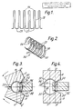
- the wire binding elements for use with such binding apparatus are formed from a length of metal wire which is bent to form a series of curved, hair-pin shaped prongs.
- the curvature of the prongs is such that the element has the appearance of an open-sided cylinder with a substantially C-shaped cross-section.
- binding elements will hereinafter be referred to as binding elements of the type described.
- the elements are closed to ring shape by bringing their closed ends or 'points' into the vicinity of their open ends or 'roots', during which proceedure the prongs are forced through the perforations of appropriately positioned bundles of sheets.
- the closing of the binding elements through the sheets is performed by two opposed closing jaws provided in the binding apparatus, between which binding elements of the type described and bundles of perforated sheets are fed.
- the closing jaws of the binding apparatus have a working surface which is a segment of a cylinder, the diameter of which corresponds to the diameter of the binding elements when closed, and are arranged to rotate in opposite directions about a fixed horizontal axis or pivot centre. As the jaws pivot, a force is applied by the working surfaces to the binding element which forces the prongs through the perforations and closes it as previously described.
- the binding apparatus is also provided with means to feed binding elements and perforated sheets to the feeding jaws between each binding stroke. Binding element feed mechanisms are disclosed in our GB Patent Nos 1209940 and 1541225.
- the closing jaws should be set so that the edge of the working surface, which, in use, is adjacent the bundle of sheets to be bound, exactly coincides with the pivot centre of each jaw. Should the jaw not be so positioned then the edge of the working surface of the jaw will sweep in an arc when closing and the working surface will not be properly aligned to produce the correct curvature of the binding elements when closed.
- Apparatus for binding perforated sheets with wire binding elements of the type described in accordance with the invention comprises a pair of opposed closing jaws, between which binding elements and bundles of perforated sheets are fed, the closing jaws each having a working surface which is a segment of a cylinder and being adapted to rotate in opposite directions about pivot centres, the pivot centre for each jaw being aligned with the edge of the working surface adjacent the bundle of sheets to be bound, wherein means are provided to adjust the position of the pivot centres towards and away from each other to accommodate closing jaws of different sizes.
- pivot centres are movable in a single vertical plane through the binding apparatus.
- the path of rotation of the closing jaws may be dictated by the curvature of a cam surface formed in a cam block.
- the jaws are removably attached to carrier blocks which have a follower attached thereto which engages the cam surface.
- the position of the pivot centres may be adjusted by moving the cam blocks towards and away from one another.
- the cam blocks may be slidably mounted on support blocks with wedge members inserted therebetween, the position of the cam blocks.
- the movement of the wedge members is facilitated by rotation of actuating levers connected thereto by link members.
- Rotation of the actuating levers in a clockwise direction is preferably arranged to move the cam blocks and hence the pivot centres towards one another and rotation of the actuating levers in an anti-clockwise direction moves the cam blocks and pivot centres away from one another.
- the actuating levers may be operated manually, or automatically.
- the closing jaws may be connected by levers to a main horizontal shaft, which shaft has connected thereto a pneumatic jack, a fixed stroke of the jack causing the shaft to rotate and the closing jaws to pivot about the pivot centres.
- the connecting means between the jack and the shaft is a split lever comprising two portions which are pivotable with respect to the other and secured to the main shaft, the pivotable portion being lockable in a predetermined angular relationship with the fixed portion. The two portions of the lever may be locked together by bolts.
- Binding apparatus in accordance with the invention may be fitted with a single pair of jaw carrier blocks which are shaped to receive many different sets of of closing jaws to suit particular binding elements.
- the pivot centre can be adjusted, by raising and lowering the cam blocks, so that it coincides with the edge of the working surface adjacent the bundles of sheets to be bound.
- the metal wire to be used as a book binding element is bent to form a series of curved hairpin shaped prongs 28 having straight sections 29 therebetween.
- Each prong 28 has a point 26 and a root 27.
- the wire binding element 36 is curved to have a substantially C-shaped cross-section and forms an open-sided cylinder.
- the cyclinder has a depression 38 in its wall extending over the whole of its length.
- the jaws 8 and 9 have working surfaces 30 which are segments of cylinders whose centres are on the line X-X.
- the jaws 8 and 9 are arranged to pivot about pivot centres 24 and 24′ which are in the plane Y-Y.
- the pivot centres 24 and 24′ are equidistant from the horizontal centre line C L and are spaced apart a distance slightly greater than the maximum thickness of a book 32 whose leaves are to be bound in the apparatus.
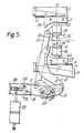
- the position of the closing jaws within the binding apparatus is shown in Figure 5.
- the jaws 8 and 9 are mounted on tool carrier blocks 8A and 9A.
- Each tool carrier block 8A and 9A is pivotally connected to levers 10 and 12 respectively.
- the levers 10 and 12 extend downwardly from the tool carrier blocks, their lower ends being attached to connecting levers 11 and 13 which themselves are secured to the main shaft 33.
- the shaft 33 is connected to penumatic jacks 20 via a split lever 19 consisting of two components 19A and 19B.
- the two components are held fixedly together by locking bolts 25 so that a fixed stroke of the pneumatic jacks 20 causes the shaft 33 to rotate through a fixed distance. If the shaft 33 is rotated in an anti-clockwise direction the connecting levers 11 and 13 and the levers 10 and 12 act to pivot the tool carrier blocks and closing jaws 8 and 9, into the 'bind' position, about the pivot centre 24 and 24′.
- the penumatic jacks 20 are therefore arranged to be actuated once a binding element 36 and the book 32 to be bound have been correctly positioned between the closing jaws.
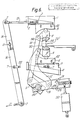
- the top or bottom respectively of the tool carrier blocks 8A and 9A are held in support brackets on which a follower 44 is attached and which engages and runs along a cam surface 23 formed in cam blocks 3 and 6.
- the curvature of the cam surface 23 dictates the path of rotation of the closing jaws 8 and 9 about pivot centres 24 and 24′. Therefore the position of the cam blocks 3 and 6 dictates the position of the pivot centres 24 and 24′ on either side of the centre line C L .
- the closing jaws 8 and 9 are positioned nearer to, or further from, the centre line C L , than the pivot centres, the edge of the working surface 40 sweeps in an arc during binding and the working surfaces 30 are incorrectly positioned for closing the binding elements 36. It is therefore necessary to adjust the position of the pivot centres 24 and 24′ when new jaws are attached to carrier blocks 8A and 9A.
- the cam blocks 3 and 6 are mounted on support blocks 1 and 4 respectively, in a slidable manner, by means of slotted links 42.
- the support blocks 1 and 4 have a space into which wedges 2 and 5 are inserted, the wedges being movable with respect to both the supporting blocks 1 and 4 and their cam blocks 3 and 6.
- the upper wedge 2 is connected to a top actuating lever 15 via linkage 21 and the wedge 5 is connected to a bottom actuating lever 16 via linkage 22.
- the linkages 21 and 22 are ball-jointed rods or a similar rigid linkage which can be adjusted when initially setting the apparatus. The movement of the wedges 2 and 5 and hence the cam blocks 3 and 6 is shown in Figures 7 and 8.
- the actuating levers 15 and 16 are rotated about a fulcrum point given by the centre of the shaft 14.
- the top actuating lever 15 is rotated in a clockwise direction, the movement 15 transmitted to the wedge 2 via linkage 21.
- the wedge travels along the support block 1 it moves cam block 3 towards the centre line C L .
- the cam block 3 forces the closing jaw 8 and carrier 8A downwards and the pivot centre 24 is moved nearer to the centre line
- an equal rotation of the bottom actuating lever 16 in a clockwise direction about the shaft 14 occurs.
- This movement is transmitted to wedge 5 via linkage 22 and the wedge moves along support block 4, pushing as it does so, the cam block 6 upwards towards the centre line.
- the jaw 9, carrier 9A and pivot centre 24′ are moved towards the centre line a distance equal to that of jaw 8 and pivot centre 24.
- the actuating levers 15 and 16 are connected to a prime mover 17 (see Figure 6) which when pulled in the direction of the arrow rotates the levers in a clockwise direction to move the cam blocks 3 and 6 towards the centre line.
- a prime mover 17 see Figure 6
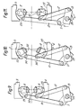
- Figure 9 shows the position of the closing jaw carriers 8A and 9A, the main shaft 33, levers 11 and 13 and cam blocks 3 and 6 when the minimum distance between the pivot centres 24 and 24′ occurs.
- the cam blocks 3 and 6 are moved away from the centre line by the wedge mechanism described previously, the pivot centres 24 and 24′ separate along the vertical plane Y-Y and the closing jaw carriers 8A and 9A rotate about points 34 and 34′ causing them to travel up the marking surfaces 23 of the cam blocks.
- the jaws 8 and 9 are therefore misaligned, as shown in Figure 10.
- the bolts 25 are then tightened to maintain the part 19A in its adjusted position and the closing jaw carrier alignment is corrected. Further the binding lever part 19B is nearer the centre of the main shaft 33 thus reducing the radius at which the pneumatic jacks are acting and ensuring sufficient rotation of the shaft when binding.
- the prime mover 17 may be manually operated by hand or treadle or automatically operated by penumatic or hydraulic jack or electric motor and gear system.
- the movement can be between two dead stops only, or incremental within a range of preset stops, or infinitely variable with a setting for upper and lower limits only. Further wedges of different angles may be combined for insertion between the cam blocks and supports.
- Wedges are not the only method available for raising and lowering the cam blocks.
- Alternatives include mounting the cam blocks on a single shaft having right and left handed threads so that rotation of the shaft moves the cam blocks towards and away from the centre line or fitting cams on two parallel shafts which are geared together so that rotation of a handwheel causes the cams to act on the cam block in the manner or overhead cams in motor cars.
- Further alternatives which may be used are direct acting levers or toggle linkages.
Landscapes
- Engineering & Computer Science (AREA)
- Textile Engineering (AREA)
- Basic Packing Technique (AREA)
- Solid-Sorbent Or Filter-Aiding Compositions (AREA)
- Wire Processing (AREA)
- Sheet Holders (AREA)
- Superconductors And Manufacturing Methods Therefor (AREA)
- Amplifiers (AREA)
- Materials For Medical Uses (AREA)
- Decoration Of Textiles (AREA)
- Laminated Bodies (AREA)
Priority Applications (1)
| Application Number | Priority Date | Filing Date | Title |
|---|---|---|---|
| AT88311933T ATE83978T1 (de) | 1987-12-22 | 1988-12-16 | Binden von gelochten boegen. |
Applications Claiming Priority (2)
| Application Number | Priority Date | Filing Date | Title |
|---|---|---|---|
| GB8729897A GB2213769B (en) | 1987-12-22 | 1987-12-22 | Improvements in and relating to the binding of perforated sheets |
| GB8729897 | 1987-12-22 |
Publications (3)
| Publication Number | Publication Date |
|---|---|
| EP0322163A2 true EP0322163A2 (fr) | 1989-06-28 |
| EP0322163A3 EP0322163A3 (en) | 1990-02-28 |
| EP0322163B1 EP0322163B1 (fr) | 1992-12-30 |
Family
ID=10628884
Family Applications (1)
| Application Number | Title | Priority Date | Filing Date |
|---|---|---|---|
| EP88311933A Expired - Lifetime EP0322163B1 (fr) | 1987-12-22 | 1988-12-16 | Reliure de feuilles perforées |
Country Status (11)
| Country | Link |
|---|---|
| US (1) | US4934890A (fr) |
| EP (1) | EP0322163B1 (fr) |
| AT (1) | ATE83978T1 (fr) |
| DE (1) | DE3877172T2 (fr) |
| DK (1) | DK169774B1 (fr) |
| ES (1) | ES2037249T3 (fr) |
| GB (1) | GB2213769B (fr) |
| HK (2) | HK72992A (fr) |
| IE (1) | IE62115B1 (fr) |
| NO (1) | NO174496B (fr) |
| SG (1) | SG56492G (fr) |
Cited By (3)
| Publication number | Priority date | Publication date | Assignee | Title |
|---|---|---|---|---|
| US4934890A (en) * | 1987-12-22 | 1990-06-19 | James Burn International Limited | Binding of perforated sheets |
| EP1216843A2 (fr) | 2000-12-06 | 2002-06-26 | Bertelsmann Kalender & Promotion Service GmbH | Calendrier mural avec une fixation détachable |
| US9862221B2 (en) | 2011-07-18 | 2018-01-09 | ACCO Brands Corporation | Binding system for retaining bound components |
Families Citing this family (21)
| Publication number | Priority date | Publication date | Assignee | Title |
|---|---|---|---|---|
| DE3941648A1 (de) * | 1989-12-16 | 1991-06-20 | Renz Chr Gmbh & Co | Vorrichtung zum einkaemmen und binden von gestanzten einzelblaettern |
| GB2259273B (en) * | 1991-08-19 | 1995-01-11 | Burn James Int Ltd | Improvements in and relating to binding perforated sheets |
| US5211522A (en) * | 1992-05-26 | 1993-05-18 | Jackson Ho | Punching and binding machine |
| US5452980A (en) * | 1994-01-13 | 1995-09-26 | Whiteman, Jr.; Marvin E. | Electric loop wire bindery press |
| US5454679A (en) * | 1994-01-13 | 1995-10-03 | Whiteman, Jr.; Marvin E. | Wire element bindery press |
| US6044546A (en) * | 1996-03-22 | 2000-04-04 | Max Co., Ltd. | Apparatus for clipping a sheet member |
| GB9712718D0 (en) * | 1997-06-18 | 1997-08-20 | Heights Design Production Ltd | Binding apparatus |
| AU2433501A (en) * | 1999-12-17 | 2001-06-25 | General Binding Corporation | Binding apparatus |
| AU2002217778A1 (en) | 2000-11-22 | 2002-06-03 | General Binding Corporation | Plurality of binding elements for automated processes |
| US20020106265A1 (en) * | 2000-11-29 | 2002-08-08 | Mario Litsche | Binding apparatus and method |
| US20040240967A1 (en) * | 2001-08-29 | 2004-12-02 | Phillip Crudo | Binding elements for binding a wide range of thicknesses of stacks of sheets |
| US20040018041A1 (en) * | 2001-11-20 | 2004-01-29 | Samuel Amdahl | Plurality of binding elements for automated processes |
| US6887025B2 (en) * | 2002-01-31 | 2005-05-03 | Performance Design, Inc. | Combined inserter and binder for wire element |
| DE10223481A1 (de) * | 2002-05-27 | 2003-12-11 | Heidelberger Druckmasch Ag | Verfahren zum Biegen von Drahtkammbindeelementen |
| US20030031502A1 (en) * | 2002-08-30 | 2003-02-13 | Rothschild Wayne H. | Binding element stacking structure |
| JP2004338221A (ja) * | 2003-05-15 | 2004-12-02 | Carl Manufacturing Co Ltd | 綴じ具 |
| US20050238414A1 (en) * | 2004-04-16 | 2005-10-27 | General Binding Corporation | Disposable clip for coupling binding elements and combination of binding elements with disposable coupling clip |
| CA2573096A1 (fr) * | 2004-07-12 | 2006-02-16 | General Binding Corporation | Element de reliure et pluralite d'elements de reliure adaptes a des processus automatises |
| US8123448B2 (en) * | 2005-08-16 | 2012-02-28 | General Binding Corporation | Apparatus and methods for automatically binding a stack of sheets with a nonspiral binding element |
| USD620977S1 (en) | 2006-08-04 | 2010-08-03 | General Binding Corporation | Binding element |
| ES2362829T3 (es) * | 2008-10-17 | 2011-07-13 | Kugler-Womako Gmbh | Encuadernación de piezas planas apiladas unas encima de otras. |
Family Cites Families (6)
| Publication number | Priority date | Publication date | Assignee | Title |
|---|---|---|---|---|
| FR1542471A (fr) * | 1966-12-06 | 1968-10-18 | Machine à relier automatique | |
| US3451081A (en) * | 1968-01-03 | 1969-06-24 | Burn & Co Ltd James | Book-binding machines |
| GB1541225A (en) * | 1975-02-13 | 1979-02-28 | Burn Bindings Ltd James | Binding of perforated sheets |
| CH654528A5 (de) * | 1980-11-08 | 1986-02-28 | Womako Masch Konstr | Verfahren und vorrichtung zum herstellen von bloecken mit drahtkammbindung. |
| EP0095243A1 (fr) * | 1982-05-21 | 1983-11-30 | James Burn Bindings Limited | Perfectionnements aux machines à relier au moyen de fil métallique |
| GB2213769B (en) * | 1987-12-22 | 1992-01-02 | Burn James Int Ltd | Improvements in and relating to the binding of perforated sheets |
-
1987
- 1987-12-22 GB GB8729897A patent/GB2213769B/en not_active Expired - Fee Related
-
1988
- 1988-12-16 EP EP88311933A patent/EP0322163B1/fr not_active Expired - Lifetime
- 1988-12-16 DE DE8888311933T patent/DE3877172T2/de not_active Expired - Fee Related
- 1988-12-16 ES ES198888311933T patent/ES2037249T3/es not_active Expired - Lifetime
- 1988-12-16 AT AT88311933T patent/ATE83978T1/de active
- 1988-12-20 IE IE379688A patent/IE62115B1/en not_active IP Right Cessation
- 1988-12-20 US US07/286,899 patent/US4934890A/en not_active Expired - Fee Related
- 1988-12-21 NO NO885691A patent/NO174496B/no not_active IP Right Cessation
- 1988-12-22 DK DK717388A patent/DK169774B1/da not_active IP Right Cessation
-
1992
- 1992-05-29 SG SG564/92A patent/SG56492G/en unknown
- 1992-09-24 HK HK729/92A patent/HK72992A/xx not_active IP Right Cessation
-
1997
- 1997-12-23 HK HK97102599A patent/HK1000960A1/en not_active IP Right Cessation
Cited By (4)
| Publication number | Priority date | Publication date | Assignee | Title |
|---|---|---|---|---|
| US4934890A (en) * | 1987-12-22 | 1990-06-19 | James Burn International Limited | Binding of perforated sheets |
| EP1216843A2 (fr) | 2000-12-06 | 2002-06-26 | Bertelsmann Kalender & Promotion Service GmbH | Calendrier mural avec une fixation détachable |
| US9862221B2 (en) | 2011-07-18 | 2018-01-09 | ACCO Brands Corporation | Binding system for retaining bound components |
| US10569590B2 (en) | 2011-07-18 | 2020-02-25 | ACCO Brands Corporation | Binding system for retaining bound components |
Also Published As
| Publication number | Publication date |
|---|---|
| IE883796L (en) | 1989-06-22 |
| SG56492G (en) | 1992-07-24 |
| EP0322163A3 (en) | 1990-02-28 |
| GB2213769B (en) | 1992-01-02 |
| DK717388D0 (da) | 1988-12-22 |
| NO885691L (no) | 1989-06-23 |
| DK169774B1 (da) | 1995-02-27 |
| EP0322163B1 (fr) | 1992-12-30 |
| US4934890A (en) | 1990-06-19 |
| DE3877172T2 (de) | 1993-05-06 |
| HK72992A (en) | 1992-10-02 |
| IE62115B1 (en) | 1994-12-14 |
| NO174496B (no) | 1994-02-07 |
| DE3877172D1 (de) | 1993-02-11 |
| ATE83978T1 (de) | 1993-01-15 |
| GB2213769A (en) | 1989-08-23 |
| NO885691D0 (no) | 1988-12-21 |
| ES2037249T3 (es) | 1993-06-16 |
| HK1000960A1 (en) | 1998-05-15 |
| DK717388A (da) | 1989-06-23 |
| GB8729897D0 (en) | 1988-02-03 |
| NO174496C (fr) | 1994-05-18 |
Similar Documents
| Publication | Publication Date | Title |
|---|---|---|
| EP0322163B1 (fr) | Reliure de feuilles perforées | |
| HK1000960B (en) | Improvements in and relating to the binding of perforated sheets | |
| DE102019213323B4 (de) | Clipmodul zur Positionierung eines Clips an einer vorgegebenen Montageposition eines Leitungsstrangs sowie Montagekopf mit einem derartigen Clipmodul | |
| EP0499964A1 (fr) | Appareil pour la préparation de bretzel à partir des bandes de pâte droites d'une longueur définie | |
| EP0891878A2 (fr) | Dispositif de reliure | |
| EP0248785B1 (fr) | Dispositif pour ajouter des cadres d'espacement | |
| DE1801955A1 (de) | Vorrichtung zum Einbringen von Kettengliedern in eine Widerstandsschweissmaschine | |
| EP1939010A2 (fr) | Presse et façonneuse de livre | |
| EP0920931B1 (fr) | Dispositif pour le pliage des tôles | |
| PT89332B (pt) | Aperfeicoamentos em, e relativos a ligacao de folhas perfuradas | |
| CH364242A (de) | Maschine zum Herstellen von Broschüren | |
| DE2724528C2 (de) | Verfahren und Vorrichtung zur Herstellung einer röhrenförmigen Leuchtstofflampe in bogenförmiger Gestalt | |
| CN217046153U (zh) | 一种抓握稳定的棒材夹爪 | |
| EP0698429A1 (fr) | Dispositif de pliage en une opération d'une serie de barres parallèles formant une treillis | |
| DE40243C (de) | Kartonecken - Schliefsmaschine mit selbstthätiger Klammerbildung | |
| JPH0133221Y2 (fr) | ||
| DE119685C (fr) | ||
| DE828399C (de) | Verfahren und Maschine zum Einhaengen von Broschueren oder Buechern | |
| DE115638C (fr) | ||
| DE76085C (de) | Verfahren und Maschine zur Herstellung von Schnürstiften mit nicht streckbarer Einlage | |
| DE2520002C2 (de) | Vorrichtung zum Anbringen eines Bindestreifens an den Bindekanten eines Stapels von Blättern | |
| DE456439C (de) | Biegemaschine fuer Betoneisenbuegel | |
| DE176851C (fr) | ||
| DE29791C (de) | Maschine zum Bebinden der Flaschenkorke mit Draht | |
| DE131007C (fr) |
Legal Events
| Date | Code | Title | Description |
|---|---|---|---|
| PUAI | Public reference made under article 153(3) epc to a published international application that has entered the european phase |
Free format text: ORIGINAL CODE: 0009012 |
|
| AK | Designated contracting states |
Kind code of ref document: A2 Designated state(s): AT BE CH DE ES FR GB GR IT LI LU NL SE |
|
| PUAL | Search report despatched |
Free format text: ORIGINAL CODE: 0009013 |
|
| AK | Designated contracting states |
Kind code of ref document: A3 Designated state(s): AT BE CH DE ES FR GB GR IT LI LU NL SE |
|
| 17P | Request for examination filed |
Effective date: 19900321 |
|
| 17Q | First examination report despatched |
Effective date: 19910826 |
|
| GRAA | (expected) grant |
Free format text: ORIGINAL CODE: 0009210 |
|
| AK | Designated contracting states |
Kind code of ref document: B1 Designated state(s): AT BE CH DE ES FR GB GR IT LI LU NL SE |
|
| PG25 | Lapsed in a contracting state [announced via postgrant information from national office to epo] |
Ref country code: GR Free format text: LAPSE BECAUSE OF FAILURE TO SUBMIT A TRANSLATION OF THE DESCRIPTION OR TO PAY THE FEE WITHIN THE PRESCRIBED TIME-LIMIT Effective date: 19921230 Ref country code: AT Effective date: 19921230 |
|
| REF | Corresponds to: |
Ref document number: 83978 Country of ref document: AT Date of ref document: 19930115 Kind code of ref document: T |
|
| REF | Corresponds to: |
Ref document number: 3877172 Country of ref document: DE Date of ref document: 19930211 |
|
| ITF | It: translation for a ep patent filed | ||
| ET | Fr: translation filed | ||
| REG | Reference to a national code |
Ref country code: ES Ref legal event code: FG2A Ref document number: 2037249 Country of ref document: ES Kind code of ref document: T3 |
|
| PLBE | No opposition filed within time limit |
Free format text: ORIGINAL CODE: 0009261 |
|
| STAA | Information on the status of an ep patent application or granted ep patent |
Free format text: STATUS: NO OPPOSITION FILED WITHIN TIME LIMIT |
|
| 26N | No opposition filed | ||
| PG25 | Lapsed in a contracting state [announced via postgrant information from national office to epo] |
Ref country code: LU Free format text: LAPSE BECAUSE OF NON-PAYMENT OF DUE FEES Effective date: 19931231 |
|
| EAL | Se: european patent in force in sweden |
Ref document number: 88311933.1 |
|
| PGFP | Annual fee paid to national office [announced via postgrant information from national office to epo] |
Ref country code: CH Payment date: 19991210 Year of fee payment: 12 |
|
| PGFP | Annual fee paid to national office [announced via postgrant information from national office to epo] |
Ref country code: SE Payment date: 20001206 Year of fee payment: 13 |
|
| PGFP | Annual fee paid to national office [announced via postgrant information from national office to epo] |
Ref country code: DE Payment date: 20001211 Year of fee payment: 13 |
|
| PGFP | Annual fee paid to national office [announced via postgrant information from national office to epo] |
Ref country code: FR Payment date: 20001212 Year of fee payment: 13 |
|
| PGFP | Annual fee paid to national office [announced via postgrant information from national office to epo] |
Ref country code: GB Payment date: 20001213 Year of fee payment: 13 |
|
| PGFP | Annual fee paid to national office [announced via postgrant information from national office to epo] |
Ref country code: ES Payment date: 20001220 Year of fee payment: 13 |
|
| PG25 | Lapsed in a contracting state [announced via postgrant information from national office to epo] |
Ref country code: LI Free format text: LAPSE BECAUSE OF NON-PAYMENT OF DUE FEES Effective date: 20001231 Ref country code: CH Free format text: LAPSE BECAUSE OF NON-PAYMENT OF DUE FEES Effective date: 20001231 |
|
| PGFP | Annual fee paid to national office [announced via postgrant information from national office to epo] |
Ref country code: NL Payment date: 20001231 Year of fee payment: 13 |
|
| PGFP | Annual fee paid to national office [announced via postgrant information from national office to epo] |
Ref country code: BE Payment date: 20010315 Year of fee payment: 13 |
|
| REG | Reference to a national code |
Ref country code: CH Ref legal event code: PL |
|
| PG25 | Lapsed in a contracting state [announced via postgrant information from national office to epo] |
Ref country code: GB Free format text: LAPSE BECAUSE OF NON-PAYMENT OF DUE FEES Effective date: 20011216 |
|
| PG25 | Lapsed in a contracting state [announced via postgrant information from national office to epo] |
Ref country code: SE Free format text: LAPSE BECAUSE OF NON-PAYMENT OF DUE FEES Effective date: 20011217 |
|
| PG25 | Lapsed in a contracting state [announced via postgrant information from national office to epo] |
Ref country code: BE Free format text: LAPSE BECAUSE OF NON-PAYMENT OF DUE FEES Effective date: 20011231 |
|
| REG | Reference to a national code |
Ref country code: GB Ref legal event code: IF02 |
|
| BERE | Be: lapsed |
Owner name: JAMES BURN INTERNATIONAL LTD Effective date: 20011231 |
|
| PG25 | Lapsed in a contracting state [announced via postgrant information from national office to epo] |
Ref country code: NL Free format text: LAPSE BECAUSE OF NON-PAYMENT OF DUE FEES Effective date: 20020701 |
|
| PG25 | Lapsed in a contracting state [announced via postgrant information from national office to epo] |
Ref country code: DE Free format text: LAPSE BECAUSE OF NON-PAYMENT OF DUE FEES Effective date: 20020702 |
|
| EUG | Se: european patent has lapsed |
Ref document number: 88311933.1 |
|
| GBPC | Gb: european patent ceased through non-payment of renewal fee |
Effective date: 20011216 |
|
| PG25 | Lapsed in a contracting state [announced via postgrant information from national office to epo] |
Ref country code: FR Free format text: LAPSE BECAUSE OF NON-PAYMENT OF DUE FEES Effective date: 20020830 |
|
| NLV4 | Nl: lapsed or anulled due to non-payment of the annual fee |
Effective date: 20020701 |
|
| REG | Reference to a national code |
Ref country code: FR Ref legal event code: ST |
|
| PG25 | Lapsed in a contracting state [announced via postgrant information from national office to epo] |
Ref country code: ES Free format text: LAPSE BECAUSE OF NON-PAYMENT OF DUE FEES Effective date: 20021217 |
|
| REG | Reference to a national code |
Ref country code: ES Ref legal event code: FD2A Effective date: 20030113 |
|
| PG25 | Lapsed in a contracting state [announced via postgrant information from national office to epo] |
Ref country code: IT Free format text: LAPSE BECAUSE OF NON-PAYMENT OF DUE FEES;WARNING: LAPSES OF ITALIAN PATENTS WITH EFFECTIVE DATE BEFORE 2007 MAY HAVE OCCURRED AT ANY TIME BEFORE 2007. THE CORRECT EFFECTIVE DATE MAY BE DIFFERENT FROM THE ONE RECORDED. Effective date: 20051216 |