EP0322230A2 - Appareil de nettoyage pour une surface â charge de rétention - Google Patents
Appareil de nettoyage pour une surface â charge de rétention Download PDFInfo
- Publication number
- EP0322230A2 EP0322230A2 EP88312153A EP88312153A EP0322230A2 EP 0322230 A2 EP0322230 A2 EP 0322230A2 EP 88312153 A EP88312153 A EP 88312153A EP 88312153 A EP88312153 A EP 88312153A EP 0322230 A2 EP0322230 A2 EP 0322230A2
- Authority
- EP
- European Patent Office
- Prior art keywords
- brush
- toner
- cleaning
- detoning
- auger
- Prior art date
- Legal status (The legal status is an assumption and is not a legal conclusion. Google has not performed a legal analysis and makes no representation as to the accuracy of the status listed.)
- Granted
Links
Images

Classifications
-
- G—PHYSICS
- G03—PHOTOGRAPHY; CINEMATOGRAPHY; ANALOGOUS TECHNIQUES USING WAVES OTHER THAN OPTICAL WAVES; ELECTROGRAPHY; HOLOGRAPHY
- G03G—ELECTROGRAPHY; ELECTROPHOTOGRAPHY; MAGNETOGRAPHY
- G03G21/00—Arrangements not provided for by groups G03G13/00 - G03G19/00, e.g. cleaning, elimination of residual charge
- G03G21/0005—Arrangements not provided for by groups G03G13/00 - G03G19/00, e.g. cleaning, elimination of residual charge for removing solid developer or debris from the electrographic recording medium
- G03G21/0035—Arrangements not provided for by groups G03G13/00 - G03G19/00, e.g. cleaning, elimination of residual charge for removing solid developer or debris from the electrographic recording medium using a brush; Details of cleaning brushes, e.g. fibre density
-
- G—PHYSICS
- G03—PHOTOGRAPHY; CINEMATOGRAPHY; ANALOGOUS TECHNIQUES USING WAVES OTHER THAN OPTICAL WAVES; ELECTROGRAPHY; HOLOGRAPHY
- G03G—ELECTROGRAPHY; ELECTROPHOTOGRAPHY; MAGNETOGRAPHY
- G03G2221/00—Processes not provided for by group G03G2215/00, e.g. cleaning or residual charge elimination
- G03G2221/0026—Cleaning of foreign matter, e.g. paper powder, from imaging member
- G03G2221/0031—Type of foreign matter
- G03G2221/0042—Paper powder and other dry foreign matter
-
- G—PHYSICS
- G03—PHOTOGRAPHY; CINEMATOGRAPHY; ANALOGOUS TECHNIQUES USING WAVES OTHER THAN OPTICAL WAVES; ELECTROGRAPHY; HOLOGRAPHY
- G03G—ELECTROGRAPHY; ELECTROPHOTOGRAPHY; MAGNETOGRAPHY
- G03G2221/00—Processes not provided for by group G03G2215/00, e.g. cleaning or residual charge elimination
- G03G2221/0026—Cleaning of foreign matter, e.g. paper powder, from imaging member
- G03G2221/0047—Type of cleaning device
- G03G2221/0052—Common container for holding cleaned foreign matter and residual toner
-
- G—PHYSICS
- G03—PHOTOGRAPHY; CINEMATOGRAPHY; ANALOGOUS TECHNIQUES USING WAVES OTHER THAN OPTICAL WAVES; ELECTROGRAPHY; HOLOGRAPHY
- G03G—ELECTROGRAPHY; ELECTROPHOTOGRAPHY; MAGNETOGRAPHY
- G03G2221/00—Processes not provided for by group G03G2215/00, e.g. cleaning or residual charge elimination
- G03G2221/0026—Cleaning of foreign matter, e.g. paper powder, from imaging member
- G03G2221/0068—Cleaning mechanism
- G03G2221/0089—Mechanical
Definitions
- This invention relates to reproduction apparatus and more particularly to cleaning apparatus for removing residual toner and debris such as paper fibres and Kaolin from a charge retentive surface forming a part of the reproduction apparatus, with subsequent electrostatic separation of toner from the debris.
- a charge retentive surface is electrostatically charged, and exposed to a light pattern of an original image to be reproduced to selectively discharge the surface in accordance therewith.
- the resulting pattern of charged and discharged areas on that surface form an electrostatic charge pattern (an electrostatic latent image) conforming to the original image.
- the latent image is developed by contacting it with a finely divided electrostatically attractable powder referred to as "toner". Toner is held on the image areas by the electrostatic charge on the surface. Thus, a toner image is produced in conformity with a light image of the original being reproduced.
- the toner image may then be transferred to a substrate (e.g., paper), and the image affixed thereto to form a permanent record of the image to be reproduced. Subsequent to development, excess toner left on the charge retentive surface is cleaned from the surface.
- a substrate e.g., paper
- excess toner left on the charge retentive surface is cleaned from the surface.
- a commercially successful mode of cleaning employed in automatic xerography utilizes a brush with soft fiber bristles which have a suitable triboelectric characteristics. While the bristles are soft they are sufficiently firm to remove residual toner particles from the charge retentive surface. In addition, webs or belts of soft fibrous or tacky materials and other cleaning systems are known.
- EP 036920-B1 discloses a magnetic brush and insulative detoning roll both of which have electrical biases applied thereto for establishing the desired electrostatic fields between the brush and the photoreceptor and between the brush and detoning roll.
- the field established between the conductive brush and the insulative photoreceptor is such that the toner on the photoreceptor is attracted to the brush.
- the detoning roll is electrically biased to a greater negative potential than the brush.
- US-A 4,494,863 to Laing discloses a toner removal device for removing residual toner and debris from a charge retentive surface after transfer of toner images from the surface.
- This device is characterized by the use of a pair of detoning rolls, one for removing toner from a biased cleaner brush and the other from removing debris such as paper fibers, Kaolin etc., from the brush.
- the rolls are electrically biased so that one of them attracts toner from the brush while the other one attracts debris.
- US-A 4,639,124 to Nye shows a similar arrangement separating colored toners collected from a magnetic brush.
- US-A 4,116,555 to Young et al. similarly discloses a a toner removal device characterized by the use of a pair of detoning rolls, one for removing toner from a biased magnetic cleaning brush and the other for removing wrong sign toner.
- a blade cleaning arrangement for removal of toner from the detoning rolls is used in the Xerox 1075 and 1090 copiers. These products use 0.05mm thick Starret steel shim stock as a scraper blade held in a channel with a plastic spring clip. When the blade requires replacement due to wear, the blade and auger channel assembly must be removed from the cleaner, the spring clip removed, the blade removed, the new blade inserted, the spring clip reinstalled and the assembly reinstalled in the cleaner. This is a time consuming operation, and difficult to perform.
- US-A 4,083,633 to Shanly and US-A 4,447,929 to Hennig et al show blade holders where the blade is held in position by its own resiliency and frictional engagement with the walls of the blade holder.
- the blade holder assembly contains the support structures of the auger tubes.
- the supports are in the form of aluminum extrusions that slide into recesses provided in the cleaner housing.
- These assemblies, including the auger tubes are removable for cleaning if required. If the cleaner was provided in a single extruded housing, desirable for cost and assembly benefits, it is possible that toner could collect between the auger tube, the holder around the auger and the cleaner extrusion.
- JP 57-198485 to Hida shows a cleaning device removable from a copying machine including a vessel in which accumulating toner collects and a seal which causes accumulating toner to drop into the vessel.
- US-A 4,436,411 to Miyoshi et al shows a developing device including a toner particle dispenser with a reciprocating slide plate to break up agglomerated masses moving along the side walls of the toner particle dispenser to prevent clogging.
- a reproduction apparatus including a charge retentive surface; image forming means for forming a latent image on the charge retentive surface; developing means for developing the latent image with toner; transfer means for transferring the developed toner image from the charge retentive surface to a support surface; and cleaning means for removing residual toner and debris from the charge retentive surface, said cleaning means comprising: a cleaning brush supported for rotation and contact with the charge retentive surface for removing residual toner and debris therefrom, said brush being electrically biased to aid in the removal of residual toner and debris from the charge retentive surface; and detoning means supported for contact with said brush, and electrically biased for removal from said brush of residual toner and debris; characterised in that said detoning means is located adjacent one or more of the positions around the brush where the brush bristles become bunched together as a result of the rotating motion of the brush and the release of the brush bristles from cleaning contact with said charge retentive surface.
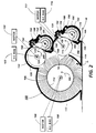
- an electrically biased fiber brush cleaning device is arranged adjacent to a photoreceptor surface at twelve o'clock position (with reference to the photoreceptor) for removing residual toner and debris deposited thereon during the operation of the machine.
- a pair of electrically biased detoning rolls are arranged at approximately the two and four o'clock positions (with reference to the cleaning brush) around the circumference of the cleaning brush for removal of toner and debris collected by the brush.
- the exact position of the first detoning roll is selected as close as possible to a first oscillation node of the fibers, the oscillation of the fibers being caused by leaving brushing contact with the photoreceptor. Positioning the detoning roll adjacent to the oscillation node enhances removal of toner from the brush, since the toner removal process takes advantage of the energy of oscillation in the movement of the fibers which tends to expel air, toner and debris therefrom.
- positioning the detoning rolls around the fiber brush and closely adjacent to the photoreceptor enhances the removal of toner and debris from the fiber brush.
- Detoning rolls are biased for removal of toner and debris having a particular charge level associated therewith.
- a poorly understood triboelectric charge transfer takes place between the brush bristles and the toner and debris. Over time, the triboelectric charge transfer varies the charge on the toner and debris beyond the charge level considered optimum for removal by biased detoning rolls.
- minimizing triboelectric charge transfer by minimization of the time that toner and debris are subject to the triboelectric effect of the brush fibers, allows the toner to be subject to removal from the brush fibers before the triboelectric effect has varied the charge on the toner and debris beyond the optimum level for removal by the biased detoning rolls.
- the detoning rolls are each provided with an identical blade cleaning structure for removal of collected toner and debris from the rolls, the blade cleaning device including an integral blade and holder slidingly engageable with a mounting position in the cleaning device housing.
- an advantageous arrangement for the support of the described cleaning device is in a unitary extrusion, in which recesses are provided for support of the detoning roll assemblies, including the associated support of detoning roll cleaning blades, augers for the removal of toner from the area about the blades, and auger extrusion liners, which allow cleaning of the auger tubes in which the augers are supported.
- the cleaning means may comprise a cleaning housing formed in a unitary extrusion and located adjacent to the charge retentive surface; a fiber brush cylindrical in cross-section, supported within a generally conforming brush portion formed in said cleaning housing for rotation and contact with the charge retentive surface for removing residual toner and debris therefrom at twelve o'clock position, said brush electrically biased to aid in the removal of residual toner and debris from the charge retentive surface; and first and second detoning means supported within detoning area recesses formed in said cleaning housing adjacent said conforming brush portion, for contact with said brush, and electrically biased for removal from said brush of residual debris and toner, respectively, each said detoning means including a detoning roll in contact with said fiber brush, a cleaning blade member for cleaning collected toner or debris from the detoning rolls and an auger means for removal of toner from the detoning means to an output.
- the cleaning means may comprise a cleaning housing formed in a unitary extrusion and located adjacent to the charge retentive surface; a cleaning blade member integrally including a blade portion and a holder portion, said holder portion slidably and removably insertable into a complementary holder recess formed in said cleaning housing to hold said cleaning blade member in operational position adjacent a surface from which toner is to be removed; and toner transport means for transporting removed toner away from the area about said cleaning blade member.
- the cleaning means may also comprise a cleaning housing formed in a unitary extrusion and located adjacent to the charge retentive surface; cleaning blade means for removing toner from a surface; and toner transport means for transporting removed toner away from the area about said cleaning blade member and including auger for transport of removed toner to an output, supported within an auger recess formed in said cleaning housing for augering motion moving toner through said auger recess to an output, and an auger extrusion liner, removably insertable into said auger recess, and sealing means, integral with said auger extrusion liner, for preventing toner from escaping said auger recess.
- a reproduction machine in which the present invention finds advantageous use utilizes a photoreceptor belt 10.
- Belt 10 moves in the direction of arrow 12 to advance successive portions of the belt sequentially through the various processing stations disposed about the path of movement thereof.
- Belt 10 is entrained about stripping roller 14, tension roller 16, idler rollers 18, and drive roller 20.
- Drive roller 20 is coupled to a motor (not shown) by suitable means such as a belt drive.
- Belt 10 is maintained in tension by a pair of springs (not shown) resiliently urging tension roller 16 against belt 10 with the desired spring force. Both stripping roller 18 and tension roller 16 are rotatably mounted. These rollers are idlers which rotate freely as belt 10 moves in the direction of arrow 16.
- a portion of belt 10 passes through charging station A.
- a pair of corona devices 22 and 24 charge photoreceptor belt 10 at a relatively high, substantially uniform negative potential.
- an original document is positioned face down on a transparent platen 30 for illumination with flash lamps 32.
- Light rays reflected from the original document are reflected through a lens 34 and projected onto a charged portion of photoreceptor belt 10 to selectively dissipate the charge thereon.
- This records an electrostatic latent image on the belt which corresponds to the informational area contained within the original document.
- belt 10 advances the electrostatic latent image to development station C.
- a magnetic brush developer unit 38 advances a developer mix (i.e. toner and carrier granules) into contact with the electrostatic latent image.
- the latent image attracts the toner particles from the carrier granules thereby forming toner powder images on photoreceptor belt 10.
- Belt 10 then advances the developed latent image to transfer station D.
- a sheet of support material such as a paper copy sheet is moved into contact with the developed latent images on belt 10.
- the latent image on belt 10 is exposed to a pretransfer light from a lamp (not shown) to reduce the attraction between photoreceptor belt 10 and the toner powder image thereon.
- corona generating device 40 charges the copy sheet to the proper potential so that it is tacked to photoreceptor belt 10 and the toner powder image is attracted from photoreceptor belt 10 to the sheet.
- a corona generator 42 charges the copy sheet to an opposite polarity to detack the copy sheet for belt 10, whereupon the sheet is stripped from belt 10 at stripping roller 14.
- Sheets of support material are advanced to transfer station D from supply trays 50, 52 and 54, which may hold different quantities, sizes and types of support materials. Sheets are advanced to transfer station D along conveyor 56 and rollers 58. After transfer, the sheet continues to move in the direction of arrow 60 onto a conveyor 62 which advances the sheet to fusing station E.
- Fusing station E includes a fuser assembly, indicated generally by the reference numeral 70, which permanently affixes the transferred toner powder images to the sheets.
- fuser assembly 70 includes a heated fuser roller 72 adapted to be pressure engaged with a back up roller 74 with the toner powder images contacting fuser roller 72. In this manner, the toner powder image is permanently affixed to the sheet.
- Chute 78 guides the advancing sheet from decurler 76 to catch tray 80 or a finishing station for binding, stapling, collating etc. and removal from the machine by the operator.
- the sheet may be advanced to a duplex tray 90 from duplex gate 92 from which it will be returned to the processor and conveyor 66 for receiving second side copy.
- a pre-clean corona generating device 94 is provided for exposing the residual toner and contaminants (hereinafter, collectively referred to as toner) to positive charges to thereby narrow the charge distribution thereon for more effective removal at cleaning station F, more completely described hereinafter. It is contemplated that residual toner remaining on photoreceptor belt 10 after transfer will be reclaimed and returned to the developer station C by any of several well known reclaim arrangements, and in accordance with the present invention, described below.
- a reproduction machine in accordance with the present invention may be any of several well known devices. Variations may be expected in specific processing, paper handling and control arrangements without affecting the present invention.
- cleaning station F includes a fiber brush cleaning arrangement having dual detoning rolls for the removal of residual toner and debris from belt 10.
- a captive fiber cleaning brush 100 is supported for rotational movement in the direction of the arrow 102 via motor 104, within a cleaning housing 106, and negatively biased by means of a D.C. power source 108.
- a fiber brush may advantageously comprise a large number of conductive cleaning fibers 110 supported on a cylindrical conductive member 112.
- housing 106 may be economically manufactured in a unitary extrusion, with recesses formed in accordance with component requirements.
- Residual toner and contaminants or debris such as paper fibers and Kaolin are removed from the photoreceptor belt 10 surface by means of a brushing action of the fibers 110 against belt 10 and the electrostatic charge applied to the fibers from by the D.C. power supply 108.
- brush 100 will remove both toner and debris from the photoreceptor, the former having a positive and the latter having a negative charge. Negatively charged contaminants are removed along with the positively charged toner particles to which they may be adhered.
- brush fibers 110 bearing toner and debris removed from belt 10 are first contacted by a first detoning roll 114 supported for rotation in the direction of arrow 115, the same direction as as brush 100 by means of a motor 117.
- An electrical bias is supplied to first detoning roll 114 from D.C. power supply 116.
- detoning roll 114 is supported in operational position against brush 100, closely spaced to the position where brush fibers 110 leave contact with the surface of photoreceptor belt 10. The position of detoning roll 114 is selected so that the brush fibers 110 are contacted by the detoning roll closely adjacent to the first oscillation node I after contact with the photoreceptor is ended.
- This oscillation node positions vary around the circumference of the brush in accordance with the speed of the cleaning brush. It is additionally desirable that this position also be located closely adjacent to the photoreceptor, so that a minimum amount of time is allowed for charge triboelectric charge exchange between the toner and debris and the brush fibers. In this manner, the bias level on the detoning rolls may be selected to obtain optimum attraction of debris.
- a second detoning roll 120 is provided for further removal of the preponderance of residual toner from the brush at a location spaced along the circumference of the brush.
- a motor 122 drives the roll in the detection of the arrow 124, the same direction as fiber brush 100 and roll 114.
- An electrical bias is supplied to the roll 120 from a source of D.C. power 123.
- the cleaning brush is biased to a potential of about -250 V, while the first detoning roll is biased to about -50V and the second detoning roll is biased to about -650 V.
- the first and second detoning rolls were located at approximately four o'clock and two o'clock positions around a cleaning brush (with reference to the cleaning brush).
- the detoning rolls are located around the cleaning brush in positions approximately one sixth and one third of a revolution from the cleaning position in the direction of rotation of the brush.
- the cleaning brush is situated at 12 o'clock with respect to photoreceptor belt 10.
- the positions of the detoning rolls may vary in accordance with the speed of the cleaning brush.
- Recesses 130 and 132 in cleaning housing 106 are provided for the support of the detoning rolls 114 and 120 respectively therein. Within these recesses, and removed from cleaning brush 100, are located blade and auger arrangements for the chiseling removal of toner from the detoning rolls and movement of the toner to a storage area or to the developing station. It is an advantage of the described invention, that by arranging the detoning rolls on a single side of the cleaning brush 100, preferably the "uphill" side between the 12 o'clock and 5 o'clock positions on the cleaner brush, the detoning roll, blade and auger arrangements may be substantially identical.
- each detoning roll is provided with an associated cleaning blade 150 supported in chiseling contact with each detoning roll in a molded blade holder 152, which is slidably insertable into integrally formed, complementary blade holder recesses 154 and 156 in housing 106.
- the integral arrangement of blade 150 and blade holder 152 allows for simple removal from blade holder recesses 154 and 156, and replacement without concern for replacement of spring loaded mounting apparatus.
- augers 170 are supported for rotating movement within auger recesses 180 and 182, formed in the cleaning housing adjacent to recesses 130 and 132 for the detoning rolls.
- the augers are supported within the cleaning housing within liners 184 formed in plastic to fit into the auger recesses, and which are slidably removable from the tubes for cleaning and service.
- Liners 184 are advantageously provided with a pair of wings 188 and 190 which are seated in slots 192, 194, 196 and 198 integrally formed in the auger recesses of the cleaning housing.
- a film seal member 200 is provided on liners 184, attached with an adhesive to an exterior surface of liner 184, so that it extends outwardly from between the lines and the auger recess.
- Film seal member 200 extends towards the blade 150, into contact with the detoning rolls, so that toner or debris chiseled from the detoning roll with the blade is maintained in the area adjacent the blade and auger arrangement, and does not enter the area between the plastic liner and the auger recess. With blade 150, film seal 200 effectively seals the auger arrangement from the remainder of the cleaning station and prevents toner clouds created by the blade and auger from dispersing outside of the auger/blade cavity.
Landscapes
- Physics & Mathematics (AREA)
- General Physics & Mathematics (AREA)
- Cleaning In Electrography (AREA)
Applications Claiming Priority (2)
| Application Number | Priority Date | Filing Date | Title |
|---|---|---|---|
| US135962 | 1987-12-21 | ||
| US07/135,962 US4819026A (en) | 1987-12-21 | 1987-12-21 | Cleaning apparatus for a charge retentive surface |
Publications (3)
| Publication Number | Publication Date |
|---|---|
| EP0322230A2 true EP0322230A2 (fr) | 1989-06-28 |
| EP0322230A3 EP0322230A3 (en) | 1989-10-18 |
| EP0322230B1 EP0322230B1 (fr) | 1992-12-02 |
Family
ID=22470597
Family Applications (1)
| Application Number | Title | Priority Date | Filing Date |
|---|---|---|---|
| EP88312153A Expired EP0322230B1 (fr) | 1987-12-21 | 1988-12-21 | Appareil de nettoyage pour une surface â charge de rétention |
Country Status (4)
| Country | Link |
|---|---|
| US (1) | US4819026A (fr) |
| EP (1) | EP0322230B1 (fr) |
| JP (1) | JP2682855B2 (fr) |
| DE (1) | DE3876403T2 (fr) |
Families Citing this family (32)
| Publication number | Priority date | Publication date | Assignee | Title |
|---|---|---|---|---|
| US4819026A (en) | 1987-12-21 | 1989-04-04 | Xerox Corporation | Cleaning apparatus for a charge retentive surface |
| JPH01219881A (ja) * | 1988-02-29 | 1989-09-01 | Alps Electric Co Ltd | クリーニング方法及び装置 |
| JP2754010B2 (ja) * | 1988-05-23 | 1998-05-20 | 株式会社リコー | 画像形成装置に於ける像担持体のクリーニング方法 |
| US4970560A (en) * | 1988-12-22 | 1990-11-13 | Xerox Corporation | Lubricated metal cleaning blade for use in dry electrophotographic processes |
| US4978999A (en) * | 1989-04-17 | 1990-12-18 | Xerox Corporation | Fiber reinforced cleaning blade |
| US4937633A (en) * | 1989-07-21 | 1990-06-26 | Xerox Corporation | Cleaning blade defect sensing arrangement |
| JP2633691B2 (ja) * | 1989-07-31 | 1997-07-23 | 株式会社東芝 | 画像形成装置 |
| US4989047A (en) * | 1989-12-11 | 1991-01-29 | Xerox Corporation | Cleaning apparatus for the reduction of agglomeration-caused spotting |
| GB2240949B (en) * | 1990-02-20 | 1993-10-20 | Xerox Corp | Fibre traps in copiers |
| US5128725A (en) * | 1990-08-20 | 1992-07-07 | Xerox Corporation | Method and apparatus for increasing toner loading of a cleaning brush for improved surface cleaning in electrophotographic imaging |
| JP2986120B2 (ja) * | 1991-03-27 | 1999-12-06 | 株式会社リコー | クリーニング装置 |
| EP0512362A3 (en) * | 1991-05-02 | 1993-05-26 | Mita Industrial Co. Ltd. | Cleaning unit for removing residual toner on photoreceptor drum for use in image forming apparatus |
| US5229817A (en) * | 1992-03-27 | 1993-07-20 | Xerox Corporation | Apparatus for monitoring wear of a toner removal device |
| US5663788A (en) * | 1992-04-02 | 1997-09-02 | Ricoh Company, Ltd. | Efficiently removable developing toner in an electrostatic image forming apparatus |
| US5278620A (en) * | 1992-07-08 | 1994-01-11 | Xerox Corporation | Cleaning blade equipped with a vibration sensor |
| US5241352A (en) * | 1992-09-21 | 1993-08-31 | Xerox Corporation | Air detoned cleaner brush |
| JP3313190B2 (ja) * | 1992-09-28 | 2002-08-12 | 株式会社リコー | 画像形成装置 |
| US5353106A (en) * | 1992-11-03 | 1994-10-04 | Xerox Corporation | Pressure roll cleaner |
| US5625443A (en) * | 1993-12-24 | 1997-04-29 | Fuji Xerox Co., Ltd. | Cleaning device for the xerography machine |
| US5512995A (en) * | 1994-08-22 | 1996-04-30 | Xerox Corporation | Non-uniform scraper blade load to increase detoning roll life |
| US5597419A (en) * | 1994-12-17 | 1997-01-28 | Xerox Corporation | Slow brush rotation in standby to avoid brush flat spots |
| US5600425A (en) * | 1995-12-18 | 1997-02-04 | Xerox Corporation | Cleaner system with central augering |
| US6986418B2 (en) * | 1998-12-10 | 2006-01-17 | Martin Engineering Company | Conveyor belt cleaner scraper blade with sensor and control system therefor |
| US6591969B2 (en) * | 1998-12-10 | 2003-07-15 | Martin Engineering Company | Conveyor belt cleaner scraper blade with sensor and method of manufacture |
| US6374990B1 (en) | 1998-12-10 | 2002-04-23 | Martin Engineering Company | Conveyor belt cleaner scraper blade with sensor |
| US6690899B2 (en) * | 2001-09-05 | 2004-02-10 | Nexpress Solutions Llc | Conductive fiber brush cleaner having separate detoning and scavenging zones |
| US6928252B2 (en) * | 2002-03-29 | 2005-08-09 | Brother Kogyo Kabushiki Kaisha | Process unit and image forming apparatus having a structure to remove foreign matter |
| DE102006007442A1 (de) * | 2006-02-17 | 2007-08-23 | BSH Bosch und Siemens Hausgeräte GmbH | Reinigungsvorrichtung für ein Bauteil eines Haushaltswäschetrockners |
| US8314953B2 (en) * | 2007-09-07 | 2012-11-20 | Xerox Corporation | System and method for processing a highlight color print job |
| US8774697B2 (en) | 2011-07-29 | 2014-07-08 | Eastman Kodak Company | Electrophotographic printer and transitional cleaning system |
| JP5754422B2 (ja) | 2012-07-20 | 2015-07-29 | コニカミノルタ株式会社 | クリーニング装置 |
| JP6206367B2 (ja) * | 2014-09-22 | 2017-10-04 | 京セラドキュメントソリューションズ株式会社 | 画像形成装置 |
Family Cites Families (18)
| Publication number | Priority date | Publication date | Assignee | Title |
|---|---|---|---|---|
| US3580673A (en) * | 1968-08-26 | 1971-05-25 | Xerox Corp | Cleaning apparatus |
| US3572923A (en) * | 1968-08-26 | 1971-03-30 | Xerox Corp | Cleaning method and apparatus for electrostatic copying machines |
| US3655373A (en) * | 1968-08-26 | 1972-04-11 | Xerox Corp | Cleaning method for electrostatic copying machines |
| US3722018A (en) * | 1971-11-08 | 1973-03-27 | Xerox Corp | Cleaning apparatus |
| US3780391A (en) * | 1972-06-09 | 1973-12-25 | Eastman Kodak Co | Apparatus for cleaning a residual image from a photosensitive member |
| US4116555A (en) * | 1975-10-29 | 1978-09-26 | Xerox Corporation | Background removal apparatus |
| US4054381A (en) * | 1976-04-05 | 1977-10-18 | Xerox Corporation | Toner filter arrangement |
| US4083633A (en) * | 1976-06-28 | 1978-04-11 | Xerox Corporation | Blade cleaning holder |
| CA1184591A (fr) * | 1980-03-17 | 1985-03-26 | Donald A Seanor | Systeme de nettoyage a balai magnetique |
| JPS56146155A (en) * | 1980-04-15 | 1981-11-13 | Mita Ind Co Ltd | Electrostatic copying machine |
| CH654508A5 (de) * | 1981-03-17 | 1986-02-28 | Gebr Hennig Gmbh | Abstreifer sowie werkzeug zur montage dieses abstreifers. |
| JPS57198485A (en) * | 1981-05-30 | 1982-12-06 | Ricoh Co Ltd | Cleaning device |
| JPS5888261U (ja) * | 1981-12-04 | 1983-06-15 | 株式会社リコー | クリ−ニング装置 |
| US4494863A (en) * | 1983-07-25 | 1985-01-22 | Xerox Corporation | Cleaning apparatus for a charge retentive surface |
| JPS6084963U (ja) * | 1983-11-17 | 1985-06-12 | 株式会社リコー | 電子写真複写機のフア−ブラシクリ−ニング装置 |
| US4571071A (en) * | 1984-04-13 | 1986-02-18 | Eastman Kodak Company | Cleaning apparatus and method for a polychromatic electrophotographic copier |
| US4639124A (en) * | 1985-11-07 | 1987-01-27 | Xerox Corporation | Cleaning system for a multicolor electrophotographic printing machine |
| US4819026A (en) | 1987-12-21 | 1989-04-04 | Xerox Corporation | Cleaning apparatus for a charge retentive surface |
-
1987
- 1987-12-21 US US07/135,962 patent/US4819026A/en not_active Expired - Lifetime
-
1988
- 1988-12-14 JP JP63316057A patent/JP2682855B2/ja not_active Expired - Fee Related
- 1988-12-21 DE DE8888312153T patent/DE3876403T2/de not_active Expired - Fee Related
- 1988-12-21 EP EP88312153A patent/EP0322230B1/fr not_active Expired
Also Published As
| Publication number | Publication date |
|---|---|
| JP2682855B2 (ja) | 1997-11-26 |
| JPH01195485A (ja) | 1989-08-07 |
| DE3876403D1 (de) | 1993-01-14 |
| US4819026A (en) | 1989-04-04 |
| DE3876403T2 (de) | 1993-05-13 |
| EP0322230A3 (en) | 1989-10-18 |
| EP0322230B1 (fr) | 1992-12-02 |
Similar Documents
| Publication | Publication Date | Title |
|---|---|---|
| EP0322230B1 (fr) | Appareil de nettoyage pour une surface â charge de rétention | |
| EP0432453B1 (fr) | Appareil de nettoyage permettant la réduction des taches dues à des agglomérats de toneur | |
| EP0366426B1 (fr) | Dispositif électrophotographique avec un ensemble de nettoyage commandé à courant alternatif | |
| US5416572A (en) | Cleaning apparatus for an electrophotographic printing machine | |
| US4870465A (en) | Toner removal and surface abrading apparatus for a charge retentive surface | |
| US4494863A (en) | Cleaning apparatus for a charge retentive surface | |
| US4742797A (en) | Tear drop seal | |
| EP0103405B1 (fr) | Appareil pour enlever du toner | |
| US4999679A (en) | Cleaning apparatus with housing and brush biased to the same magnitude and polarity | |
| US5329344A (en) | Lubrication of a detoning roll | |
| EP0322231B1 (fr) | Transport de toner par aile rotative pour nettoyage par lames sur surfaces horizontales | |
| US6259882B1 (en) | Cleaning brush for non-imaging surfaces in an electrostatographic printer or copier | |
| US4786937A (en) | Processing cartridge with one time function sheet | |
| US4527887A (en) | Blade cleaner for a charge-retentive surface | |
| US5479249A (en) | Brush cleaner with roll detoning and air waste removal | |
| US4547063A (en) | Moving magnet cleaner | |
| US5315358A (en) | Flicker bar with an integral air channel | |
| US5608499A (en) | Apparatus and method for cleaning rollers in image formers | |
| US5381218A (en) | Conductive cleaning brush belt and detoning thereof | |
| EP1031889A1 (fr) | Lame de chargement et de nettoyage combiné | |
| US6169872B1 (en) | Electrostatic cleaning belt brush | |
| US5241351A (en) | Multi-blade turret holder | |
| US5034779A (en) | Fibre traps in electrostatographic machines | |
| EP0620508A1 (fr) | Brosse électrostatique renforcée | |
| JPH0531152B2 (fr) |
Legal Events
| Date | Code | Title | Description |
|---|---|---|---|
| PUAI | Public reference made under article 153(3) epc to a published international application that has entered the european phase |
Free format text: ORIGINAL CODE: 0009012 |
|
| AK | Designated contracting states |
Kind code of ref document: A2 Designated state(s): DE FR GB |
|
| PUAL | Search report despatched |
Free format text: ORIGINAL CODE: 0009013 |
|
| AK | Designated contracting states |
Kind code of ref document: A3 Designated state(s): DE FR GB |
|
| 17P | Request for examination filed |
Effective date: 19900411 |
|
| 17Q | First examination report despatched |
Effective date: 19920205 |
|
| GRAA | (expected) grant |
Free format text: ORIGINAL CODE: 0009210 |
|
| AK | Designated contracting states |
Kind code of ref document: B1 Designated state(s): DE FR GB |
|
| ET | Fr: translation filed | ||
| REF | Corresponds to: |
Ref document number: 3876403 Country of ref document: DE Date of ref document: 19930114 |
|
| PLBE | No opposition filed within time limit |
Free format text: ORIGINAL CODE: 0009261 |
|
| STAA | Information on the status of an ep patent application or granted ep patent |
Free format text: STATUS: NO OPPOSITION FILED WITHIN TIME LIMIT |
|
| 26N | No opposition filed | ||
| REG | Reference to a national code |
Ref country code: GB Ref legal event code: IF02 |
|
| PGFP | Annual fee paid to national office [announced via postgrant information from national office to epo] |
Ref country code: FR Payment date: 20031210 Year of fee payment: 16 |
|
| PGFP | Annual fee paid to national office [announced via postgrant information from national office to epo] |
Ref country code: GB Payment date: 20031217 Year of fee payment: 16 |
|
| PGFP | Annual fee paid to national office [announced via postgrant information from national office to epo] |
Ref country code: DE Payment date: 20040102 Year of fee payment: 16 |
|
| PG25 | Lapsed in a contracting state [announced via postgrant information from national office to epo] |
Ref country code: GB Free format text: LAPSE BECAUSE OF NON-PAYMENT OF DUE FEES Effective date: 20041221 |
|
| PG25 | Lapsed in a contracting state [announced via postgrant information from national office to epo] |
Ref country code: DE Free format text: LAPSE BECAUSE OF NON-PAYMENT OF DUE FEES Effective date: 20050701 |
|
| GBPC | Gb: european patent ceased through non-payment of renewal fee |
Effective date: 20041221 |
|
| PG25 | Lapsed in a contracting state [announced via postgrant information from national office to epo] |
Ref country code: FR Free format text: LAPSE BECAUSE OF NON-PAYMENT OF DUE FEES Effective date: 20050831 |
|
| REG | Reference to a national code |
Ref country code: FR Ref legal event code: ST |