EP0322253B1 - Abgabevorrichtung für Fruchtsaftgetränke mit späterem Mischen - Google Patents
Abgabevorrichtung für Fruchtsaftgetränke mit späterem Mischen Download PDFInfo
- Publication number
- EP0322253B1 EP0322253B1 EP88312302A EP88312302A EP0322253B1 EP 0322253 B1 EP0322253 B1 EP 0322253B1 EP 88312302 A EP88312302 A EP 88312302A EP 88312302 A EP88312302 A EP 88312302A EP 0322253 B1 EP0322253 B1 EP 0322253B1
- Authority
- EP
- European Patent Office
- Prior art keywords
- concentrate
- water
- valve
- mixing chamber
- pump
- Prior art date
- Legal status (The legal status is an assumption and is not a legal conclusion. Google has not performed a legal analysis and makes no representation as to the accuracy of the status listed.)
- Expired - Lifetime
Links
Images




Classifications
-
- B—PERFORMING OPERATIONS; TRANSPORTING
- B67—OPENING, CLOSING OR CLEANING BOTTLES, JARS OR SIMILAR CONTAINERS; LIQUID HANDLING
- B67D—DISPENSING, DELIVERING OR TRANSFERRING LIQUIDS, NOT OTHERWISE PROVIDED FOR
- B67D99/00—Subject matter not provided for in other groups of this subclass
-
- B—PERFORMING OPERATIONS; TRANSPORTING
- B67—OPENING, CLOSING OR CLEANING BOTTLES, JARS OR SIMILAR CONTAINERS; LIQUID HANDLING
- B67D—DISPENSING, DELIVERING OR TRANSFERRING LIQUIDS, NOT OTHERWISE PROVIDED FOR
- B67D1/00—Apparatus or devices for dispensing beverages on draught
- B67D1/08—Details
- B67D1/12—Flow or pressure control devices or systems, e.g. valves, gas pressure control, level control in storage containers
- B67D1/1202—Flow control, e.g. for controlling total amount or mixture ratio of liquids to be dispensed
- B67D1/1234—Flow control, e.g. for controlling total amount or mixture ratio of liquids to be dispensed to determine the total amount
-
- B—PERFORMING OPERATIONS; TRANSPORTING
- B67—OPENING, CLOSING OR CLEANING BOTTLES, JARS OR SIMILAR CONTAINERS; LIQUID HANDLING
- B67D—DISPENSING, DELIVERING OR TRANSFERRING LIQUIDS, NOT OTHERWISE PROVIDED FOR
- B67D1/00—Apparatus or devices for dispensing beverages on draught
- B67D1/0015—Apparatus or devices for dispensing beverages on draught the beverage being prepared by mixing at least two liquid components
- B67D1/0021—Apparatus or devices for dispensing beverages on draught the beverage being prepared by mixing at least two liquid components the components being mixed at the time of dispensing, i.e. post-mix dispensers
- B67D1/0022—Apparatus or devices for dispensing beverages on draught the beverage being prepared by mixing at least two liquid components the components being mixed at the time of dispensing, i.e. post-mix dispensers the apparatus comprising means for automatically controlling the amount to be dispensed
- B67D1/0034—Apparatus or devices for dispensing beverages on draught the beverage being prepared by mixing at least two liquid components the components being mixed at the time of dispensing, i.e. post-mix dispensers the apparatus comprising means for automatically controlling the amount to be dispensed for controlling the amount of each component
- B67D1/0035—Apparatus or devices for dispensing beverages on draught the beverage being prepared by mixing at least two liquid components the components being mixed at the time of dispensing, i.e. post-mix dispensers the apparatus comprising means for automatically controlling the amount to be dispensed for controlling the amount of each component the controls being based on the same metering technics
- B67D1/0037—Apparatus or devices for dispensing beverages on draught the beverage being prepared by mixing at least two liquid components the components being mixed at the time of dispensing, i.e. post-mix dispensers the apparatus comprising means for automatically controlling the amount to be dispensed for controlling the amount of each component the controls being based on the same metering technics based on volumetric dosing
-
- B—PERFORMING OPERATIONS; TRANSPORTING
- B67—OPENING, CLOSING OR CLEANING BOTTLES, JARS OR SIMILAR CONTAINERS; LIQUID HANDLING
- B67D—DISPENSING, DELIVERING OR TRANSFERRING LIQUIDS, NOT OTHERWISE PROVIDED FOR
- B67D1/00—Apparatus or devices for dispensing beverages on draught
- B67D1/08—Details
- B67D1/12—Flow or pressure control devices or systems, e.g. valves, gas pressure control, level control in storage containers
- B67D1/1202—Flow control, e.g. for controlling total amount or mixture ratio of liquids to be dispensed
- B67D1/1204—Flow control, e.g. for controlling total amount or mixture ratio of liquids to be dispensed for ratio control purposes
- B67D1/1211—Flow rate sensor
- B67D1/1218—Flow rate sensor modulating the opening of a valve
-
- B—PERFORMING OPERATIONS; TRANSPORTING
- B67—OPENING, CLOSING OR CLEANING BOTTLES, JARS OR SIMILAR CONTAINERS; LIQUID HANDLING
- B67D—DISPENSING, DELIVERING OR TRANSFERRING LIQUIDS, NOT OTHERWISE PROVIDED FOR
- B67D1/00—Apparatus or devices for dispensing beverages on draught
- B67D1/08—Details
- B67D1/12—Flow or pressure control devices or systems, e.g. valves, gas pressure control, level control in storage containers
- B67D1/1256—Anti-dripping devices
-
- B—PERFORMING OPERATIONS; TRANSPORTING
- B67—OPENING, CLOSING OR CLEANING BOTTLES, JARS OR SIMILAR CONTAINERS; LIQUID HANDLING
- B67D—DISPENSING, DELIVERING OR TRANSFERRING LIQUIDS, NOT OTHERWISE PROVIDED FOR
- B67D1/00—Apparatus or devices for dispensing beverages on draught
- B67D1/08—Details
- B67D1/12—Flow or pressure control devices or systems, e.g. valves, gas pressure control, level control in storage containers
- B67D1/1277—Flow control valves
-
- B—PERFORMING OPERATIONS; TRANSPORTING
- B67—OPENING, CLOSING OR CLEANING BOTTLES, JARS OR SIMILAR CONTAINERS; LIQUID HANDLING
- B67D—DISPENSING, DELIVERING OR TRANSFERRING LIQUIDS, NOT OTHERWISE PROVIDED FOR
- B67D1/00—Apparatus or devices for dispensing beverages on draught
- B67D1/08—Details
- B67D1/0801—Details of beverage containers, e.g. casks, kegs
- B67D2001/0827—Bags in box
- B67D2001/0828—Bags in box in pressurised housing
Definitions
- This invention relates to juice dispensing and in a preferred embodiment to dispensing orange juice from 5 + 1 concentrate at a temperature as low as about -10°F (-23°C).
- Orange juice concentrate is distributed frozen. Restaurants remove concentrate from the freezer and thaw the concentrate in a cooler prior to dispensing. The restaurant has to estimate its juice requirements at least two days in advance and place sufficient concentrate in its cooler. If the restaurant's estimates are incorrect or if someone forgets, the restaurant will run out of thawed concentrate. Also, there is often a limited amount of cooler space available for thawing orange juice concentrate. When a restaurant runs out of thawed concentrate, measures are sometimes taken to quickly thaw frozen concentrate and such measures often are inefficient and ineffective and also sometimes affect the taste of the resulting product. Orange juice concentrate has typically been 3 + 1 concentrate.
- the present invention is useful preferably with 5 + 1 concentrate, although it can be used with any desired ratio up to about 7.5 +1.
- the reduced amount of water in 5 + 1 concentrate prevents a phase change or freezing, at typical freezer temperatures of -10°F to 0°F (-23°C to -18°C).
- the 5 + 1 concentrate at freezer temperatures does not readily flow by gravity.
- a container of 0°F (-18°C) product can be inverted and no product will flow out. Also, the product is so thick that a pump's suction cannot pull product from the container. However, the product is still pliable.
- EP-A-0 266 201 Prior art within the terms of Article 54(3) EPC
- This known apparatus has a gerotor (gear rotor) pump for feeding concentrate to the mixing chamber but does not have a poppet valve or a check valve downstream of the pump.
- the present invention is characterised in that said concentrate feeding means includes a gerotor pump and a poppet valve at the outlet thereof to prevent concentrate from leaking out of said pump, and a check valve downstream from said poppet valve to prevent water from said water conduit from flowing upstream from said mixing chamber through said pump when said pump is not operating.
- the poppet valve prevents concentrate from dripping out of the pump and the check valve prevents flushing water from going up through the pump into the concentrate reservoir and diluting the concentrate.
- a preferred postmix juice dispensing system for dispensing concentrate (preferably 5 + 1 concentrate) at freezer temperatures from a flexible bag includes placing the bag in a rigid, pressurizable container, pressurizing the container to force concentrate out of the bag, feeding concentrate through a heat exchanger to raise the temperature to about 32° to 40°F (0°C to 4°C), feeding the thawed concentrate to a metering device along with water for controlling the mixture ratio, and then feeding the water and concentrate to a mixing chamber of a dispensing valve for dispensing the mixture as an orange juice beverage into a cup.
- the concentrate bag preferably incorporates a dip tube or dip strip with slots larger than the pulp in the concentrate and with an internal cross-sectional area much greater than that of the slots to facilitate flowing of the concentrate and to reduce pressure drops.
- the tube prevents the bag from blocking the internal passageway therethrough.
- Concentrate emerging from the bag can be as cold as -10°F (-23°C).
- the heat exchanger can use recirculating soda water and a heating element to prevent the water from freezing.
- Control electronics such as a microcontroller can regulate the water flow rate by use of a motorized control valve.
- the concentrate pump's motor can be adjustable and the control electronics can then also or alternatively regulate the speed of the pump motor depending on the water flow rate.
- the actual reconstituting of the metered water and concentrate can incorporate either a static or a dynamic mixer, or both.
- the dispenser includes a linear modulating solenoid valve for the water.
- the system includes separate flushing and sanitizing operations.
- the system includes under-the-counter modules that can include a canister cabinet, a water bath and a refrigeration unit.
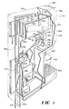
- Fig. 1 shows the preferred juice dispenser 210 of the present invention including a narrow (less than about 5 inches (12.7cm)) countertop housing 212, a water feed system, a juice concentrate feed system, a juice concentrate reservoir 214, a static mixer 216, a magnetic mixer 218, a nozzle 220, and a drip tray 222 for supporting a cup 240.
- Fig. 1A is a partial front view of the selection panel 243 of the dispenser 210 including small, medium, large, and pour/cancel buttons 244, 245, 246 and 247 respectively.
- Figs. 2-11 show the details of various components in the housing 212
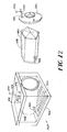
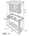
- Figs. 12-14 show the details of the under-the-counter components
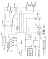
- Fig. 15 is an electrical circuit diagram showing the electrical operation of the dispenser 210
- Fig. 16 shows details of the poppet valve and check valve used in the dispenser of Fig. 1.
- the juice concentrate food system includes a concentrate inlet conduit 224 that feeds into a shut-off valve 226, and a concentrate line 228 from the shut-off valve to the reservoir 214.
- a liquid level control system including three probes 230 (high level, low level and ground) controls the concentrate level in the reservoir 214.
- Concentrate is fed from the reservoir 214 through a discharge line 232 by means of a motor 234 and pump 236 to a mixing line 238 where it begins to mix with the water, then to the mixers 216 and 218 and finally to the nozzle 220 from which the mixture is dispensed into a cup 240.
- the concentrate side of the shut-off valve 226 simply maintains a proper supply of concentrate in the reservoir. That is, when the level drops to a first predetermined lower level, the shut-off valve opens and feeds more concentrate to the reservoir until the level rises to a second predetermined higher level, when the shut-off valve again closes.
- the concentrate in the reservoir is maintained at a desired chilled temperature by means of cooling coils 242 which are in contact with the outside surface of the reservoir and which carry chilled water from a refrigeration system (not shown in Fig. 1).
- the water feed system includes a water inlet conduit 250 that feeds to both a water flow meter 252 and to the shut-off valve 226.
- the water path to the shut-off valve 226 is used for cleaning and flushing the reservoir, while the water path to the flow meter 252 is the water to be mixed with the juice concentrate to produce the beverage.
- the shut-off valve opens the water side and water flows through a water flush line 254 to a spray nozzle 256 to spray the entire insides of the reservoir.
- the motor 234 turns on and drives the pump 236 to discharge the contents of the reservoir through the mixing line 238, the mixers 216 and 218, and the nozzle 220 cleaning this entire assembly of any juice concentrate.
- the water flows into the flow meter 252, from the flow meter to a water shut-off solenoid valve 253, to a flow control valve 258 through a line 260, and from the flow control valve 258 through a discharge line 260 to connect to the mixing line 238 just upstream from the mixers 216 and 218 and the nozzle 220.
- Any suitable available flow meter can be used for the flow meter 252, such as a paddle wheel flow meter.
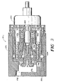
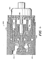
- the flow control valve 258 is shown in detail in Figs. 2-4 , and includes a body 270 having an inlet 272, an outlet 274, a chamber 276, and a control element 278.
- the control element 278 includes a solenoid 280 having an armature 282 that, when energized, moves a valve 284 from its closed position (Fig. 3 ) to its open position (Fig. 4 ) against a spring 286.
- An annular plug 288 forms a wall across the chamber 276 and has a flow opening 290 therethrough in which the valve 284 moves.
- a diaphragm 292 provides a seal for the chamber 276.
- the inlet 272 communicates with an annular groove 294 around the plug 288 and through a plurality of radial passages 296 to the interior volume 298 adjacent the opening 290.
- the solenoid 280 When the solenoid 280 is energized, water can flow through the flow control valve 258.
- the flow meter 252 can be any known flow meter to provide an electrical signal corresponding to the volume of water flowing therethrough.
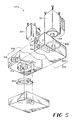
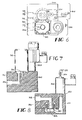
- the shut-off valve 226 is shown in detail in Figs. 5 - 8 and includes a body 300 and has a water side 302 and a concentrate side 304.
- the water side includes an inlet passageway 306, a valve seat 308, an outlet passageway 310, a solenoid 312, and an armature valve 314.
- Fig. 7 shows the water side closed; when the solenoid 312 is energized, the valve 314 moves up off the valve seat and opens the water line.
- the concentrate side of the shut-off valve 226 includes a concentrate inlet passage 316, a concentrate outlet passage 318, a valve seat 320, a diaphragm 322 for opening and closing the concentrate line by moving against or away from the valve seat 320, and a solenoid 324 having a fitting 326 for a pressurized air line and having a vent hole 330.
- a solenoid 324 having a fitting 326 for a pressurized air line and having a vent hole 330.
- the solenoid Upon energization the solenoid closes off the air line and vents the air pressure chamber 332 below the diaphragm to atmosphere, allowing the concentrate pressure to move the diaphragm down and open the passage so concentrate can now flow through the shut-off valve 226.
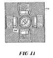
- the static and magnetic mixers are shown in Figs. 9-11 .
- the static mixer 216 includes a plurality of circumferentially staggered slots in each of which an insert 342 is placed to partially block the flow.
- an insert 342 is placed to partially block the flow.
- the magnetic mixer 218 includes a series of magnets surrounding the mixing line 238. Inside the line 238 is a magnetic rotor 344 rotably mounted between two stationary rings 346 and 348 each having four blades; the blades in the second ring are positioned at 45° to the blades in the first ring. This combination of mixers assures complete and thorough mixing.
- the nozzle 220 is located directly below the magnetic mixer 218.
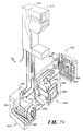
- the under-the-counter equipment comprises three separate modules: a canister cabinet 360, a water bath 362 and a refrigeration unit 364.
- the canister cabinet 360 includes a housing 366, a pressurizable canister 368, a heat exchange coil 370, a concentrate outlet fitting 372, a cooling water in fitting 374, and an overflow opening 376.
- a collapsible bag 378 of juice preferably 5+1 juice at freezer temperature (about -10°F to -0°F (-23°C to -18°C)) is shipped in a cardboard box 380, preferably hexagonal in shape.
- the bag 378 has a bag fitting 382 that mates with a canister fitting 384 when the bag and box are inserted into the canister 368.
- the canister 368 includes a removable lid 386 that seals to the canister 368.
- the lid includes a pressurized air hose connector 388 for an air hose 390.
- the hose includes a T-fitting for a hose 392 that connects to the fitting 326 on the shut-off valve 226 in the dispenser 210.
- the lid 386 is unlocked and removed, a box 380 and bag 378 are inserted into the canister and the lid is replaced and locked and sealed.
- the inside of the canister is pressurized by air to a desired pressure of about 45 psig (310KPA).
- the 5+1 concentrate can thus be pushed out through the coil 370 where it is heated to about 40° F (4°C) and flows more freely.
- the concentrate flows through a concentrate line 394 to the dispenser 210.
- the housing 366 receives water from the cooling coils 242 that surround the concentrate reservoir 214 in the dispenser 210.
- the water bath includes a tank 400, evaporator coil 402 for forming an ice bank 404, a pair of agitators 406, and a series of potable water coils 408 on the tank bottom having an inlet fitting 410 and an outlet fitting 412.
- the water line carrying the water to be used in the dispenser 210 is connected to the inlet fitting 410.
- the water inlet conduit 250 (Fig. 1 ) is connected to the outlet fitting 412.
- the refrigeration unit 364 includes a housing 420, a compressor 422, a condenser coil 424, and a pump 426.
- the evaporator coil 402 in the water bath is part of and is connected to the refrigeration unit 364.
- the refrigeration unit simply holds the refrigeration equipment, plus the pump 426.
- Fig. 15 is an electric circuit diagram showing the electrical operation of the dispenser 210.
- the dispenser, 210 of Fig. 1 has been designed with flexibility as a primary goal.
- the dispenser 210 is capable of accurately dispensing various juices at ratios in the range of from about 2.5:1 to 7.5:1 and at rates to 3 ounces (71ml) per second.
- Many smart features are incorporated into the electronics to improve functionality including a 'Teach' function which allows the machine to interactively learn various portion sizes; these sizes are then stored in non-volatile random access memory and used for automatic portion dispensing.
- Concentrate solenoid valve 324 Concentrate level probes 230. Concentrate pump motor 234 with high resolution encoder 235. Flush solenoid valve 312. Water flowmeter 252. Water shut-off solenoid valve 253. Water modulating solenoid valve 280. Dynamic juice mixer 218.
- Dual voltage remote DC power supply 432 Bi-Directional RS-232C serial communications port 436.
- Electronics 430 including a printed circuit board consisting of:
- Rates are controlled to continually achieve not only the correct mixture ratio but also to provide other beneficial features e.g., a slow ramp up at dispense initiation is necessary to reduce cup upsets then high speed dispensing proceeds to reduce dispense time and just prior to cycle termination the flow rate is ramped down to reduce foaming and spillage.
- Monitoring the two process loops also helps the processor detect anomalies in one that can be compensated for in the other e.g., a low water flow rate caused by low line pressure or a partially plugged line results in a proportionate decrease in the concentrate flow rate to maintain the pre-set ratio and vice versa.
- the processor then flashes the dual function 'Low reservoir' LED (light emitting diode) at a steady rate to indicate the low flow condition.
- the flow monitors by their very nature also provide information on the volume of fluids dispensed which is used by the 'Teach' feature to provide portion size dispensing. Depressing the 'Teach' key initiates this special mode, then a portion size key is pressed to indicate to the microprocessor that it will be "taught" the size of a 'Small', 'Medium' or 'Large' drink; the 'Pour/Cancel' key is pressed and held pressed which causes the machine to dispense product at the correct pre-set mixture ratio while the microprocessor is totalizing the quantity of each fluid dispensed. When the 'Pour/Cancel' key is released the microprocessor remembers the totalized quantities of concentrate and water dispensed and will reproduce those quantities whenever that portion size key is pressed again.
- Inventory management and diagnostic information is provided by the flow sensors and by the ability of the processor's firmware to monitor inputs and control outputs including: Number of each of the various portion sizes of drinks dispensed. Volume of each portion size. Total amount of concentrate used. Total amount of water used. Water to concentrate ratio. Size of last drink dispensed. Volume of concentrate in last drink. Volume of water in last drink. Total time to dispense last drink. Number of manual pours. Volume dispensed via manual pours. Water flow meter calibration. Pump status. Reservoir level status. Flow rate status. Status of solenoids.
- the above information is saved on-board in non-volatile static random access memory and can be monitored asynchronously as desired through the serial port.
- the serial port can also be used to change default parameters in memory to fine-tune the process, if so desired.
- the electronics 430 is preferably mounted in the dispenser 210 behind a front panel 480 that is hingedly connected at 482 to swing up and expose a circuit board 484 and make the panel holding the "Teach" button, for example, accessible.
- Fig. 16 shows the pump 236 in more detail.
- the pump is a gerotor (gear rotor) pump driven by the motor 234 and including a gear box 460 and the encoder 235. It is preferred to flush the mixing line 238 and the mixers 216 and 218 once a day with potable water from the line 260. However, because the mixers 216 and 218 are restrictions in the line, the water pressure could cause this flushing water to back up through the pump 236 and dilute the concentrate in the reservoir 214. A duckbilled check valve 462 at the outlet of the pump 236 prevents this from occurring.
- a spring loaded poppet valve 464 is located at the outlet from the pump and just upstream from the check valve 462.
- the poppet valve 464 includes a spring 466, a diaphragm 468, a piston 470, a poppet 472, and a valve seat 474.
- this invention can be used with various juices other than the preferred orange juice.
- the juice can be thawed juice, such as thawed 3+1 juice; that is, this invention is not limited to use with pliable 5+1 concentrate at freezer temperatures.
- the preferred temperature ranges are only preferred, other freezer temperatures below 32°F (0°C) can be used, and the heat exchanger can raise the temperature to any desired temperature above 32°F (0°C).
- the heat exchanger can include a water conduit, such as a recirculating soda water line that is available in the restaurant, in heat exchange relationship thereto.
- the present invention provides a postmix juice dispensing system for use with 5 + 1 concentrate at freezer temperatures.
- a postmix juice dispensing system for use with 5 + 1 concentrate at freezer temperatures in which the concentrate is contained in a flexible bag which is then placed in a pressurizable vessel which is pressurized to about 40 psig (276 KPa) to force concentrate out of the bag.
- a postmix juice dispensing system for dispensing 5 + 1 concentrate at freezer temperatures including elevating the concentrate temperature to about 32°F to 40°F (0°C to 4°C) forcing the thawed concentrate to a metering device, and then feeding the thawed and metered concentrate to a mixing chamber of a dispensing valve.
- a postmix juice dispensing system in which 5 + 1 concentrate at freezer temperatures is placed in a flexible bag in a pressurizable vessel and forced by pressure out of the flexible bag, fed through a heat exchanger, then fed through a metering device, and finally fed to a mixing chamber of a dispensing valve.
- the water flow may be controlled with linear solenoid modulation, and the provision of under-the-counter components including a canister tank, a refrigeration unit, and a water bath.
Landscapes
- Physics & Mathematics (AREA)
- Chemical & Material Sciences (AREA)
- Analytical Chemistry (AREA)
- Fluid Mechanics (AREA)
- Devices For Dispensing Beverages (AREA)
- Non-Alcoholic Beverages (AREA)
- Accessories For Mixers (AREA)
Claims (7)
- Vorrichtung zum Aufbereiten und Ausgeben von Saft, welche aufweist: einen Konzentratbehälter (360); eine Mischkammer (238) und eine Düse (220) zur Ausgabe eines Getränks hieraus; eine Konzentratleitung (224, 228, 232) zum Zuführen eines Konzentrats von dem Konzentratbehälter zu der Mischkammer; eine Wasserleitung (260) zum Zuführen von Wasser zu der Mischkammer; eine Einrichtung (258) zum Zuführen eines gesteuerten Wasservolumens durch die Wasserleitung zu der Mischkammer; und eine Einrichtung (236) zum Zuführen eines gesteuerten Konzentratvolumens zu der Mischkammer während der Ausgabe, dadurch gekennzeichnet, daß die Konzentratzufuhreinrichtung eine Rotorpumpe (236) mit innenverzahntem Rotor und ein Tellerventil (464) am Auslaß hiervon umfaßt, um zu verhindern, daß Konzentrat aus der Pumpe austritt, und daß ein Rückschlagventil (462) stromabwärts von dem Tellerventil vorgesehen ist, um zu verhindern, daß Wasser von der Wasserleitung stromaufwärts von der Mischkammer durch die Pumpe strömt, wenn die Pumpe nicht arbeitet.
- Vorrichtung nach Anspruch 1, welche ferner einen Konzentratvorratsbehälter (214) und eine Einrichtung (368) aufweist, welche automatisch den Vorratsbehälter mit Konzentrat gefüllt hält, wobei die Konzentratzufuhreinrichtung derart ausgelegt ist, daß während der Ausgabe Konzentrat von dem Vorratsbehälter zu der Mischkammer gefördert wird.
- Vorrichtung nach Anspruch 1 oder 2, bei der der Konzentratvorratsbehälter einen unter Druck setzbaren Behälter (368) aufweist, welcher eine Menge eines formbaren Saftkonzentrats bei einer Temperatur unterhalb 32°F (0°C) hält und ausgibt und bei der Einrichtungen (388, 390) zur Druckbeaufschlagung des Behälters und eine Einrichtung (370) zum Erwärmen des Konzentrats in der Konzentratleitung vorgesehen sind.
- Vorrichtung nach Anspruch 3, welche ferner ein Konzentratabsperrventil (226) in der Konzentratleitung stromabwärts von der Heizeinrichtung aufweist, wobei der Konzentratvorratsbehälter stromabwärts von dem Konzentratabsperrventil angeordnet ist.
- Vorrichtung nach einem der vorangehenden Ansprüche, bei der die Wasserzufuhreinrichtung einen linearen Modulationsmagneten (258) umfaßt.
- Vorrichtung nach Anspruch 5, welche ferner einen Durchflußmesser (252) in der Wasserleitung, ein Ein/Aus-Magnetventil (253) für Wasser in der Wasserleitung stromab von dem Durchflußmesser aufweist, wobei der lineare Modulationsmagnet (258) stromabwärts von dem Ein/Aus-Magnetventil angeordnet ist und die Wasserleitung (260) derart ausgelegt ist, daß sie Wasser von dem linearen Modulationsmagneten zu der Mischkammer fördert.
- Vorrichtung nach einem der vorangehenden Ansprüche, welche ferner eine Mikrosteuereinrichtung (430) zum Steuern der Wasserzufuhreinrichtung aufweist.
Priority Applications (1)
| Application Number | Priority Date | Filing Date | Title |
|---|---|---|---|
| AT88312302T ATE86227T1 (de) | 1987-12-23 | 1988-12-23 | Abgabevorrichtung fuer fruchtsaftgetraenke mit spaeterem mischen. |
Applications Claiming Priority (2)
| Application Number | Priority Date | Filing Date | Title |
|---|---|---|---|
| US07/137,307 US4886190A (en) | 1986-10-29 | 1987-12-23 | Postmix juice dispensing system |
| US137307 | 1987-12-23 |
Related Child Applications (4)
| Application Number | Title | Priority Date | Filing Date |
|---|---|---|---|
| EP19910202734 Division-Into EP0471422A3 (en) | 1987-12-23 | 1988-12-23 | Postmix juice dispensing system |
| EP19910202735 Division-Into EP0471423A3 (en) | 1987-12-23 | 1988-12-23 | Postmix juice dispensing system |
| EP91202734.9 Division-Into | 1988-12-23 | ||
| EP91202735.6 Division-Into | 1988-12-23 |
Publications (2)
| Publication Number | Publication Date |
|---|---|
| EP0322253A1 EP0322253A1 (de) | 1989-06-28 |
| EP0322253B1 true EP0322253B1 (de) | 1993-03-03 |
Family
ID=22476775
Family Applications (3)
| Application Number | Title | Priority Date | Filing Date |
|---|---|---|---|
| EP88312302A Expired - Lifetime EP0322253B1 (de) | 1987-12-23 | 1988-12-23 | Abgabevorrichtung für Fruchtsaftgetränke mit späterem Mischen |
| EP19910202735 Withdrawn EP0471423A3 (en) | 1987-12-23 | 1988-12-23 | Postmix juice dispensing system |
| EP19910202734 Withdrawn EP0471422A3 (en) | 1987-12-23 | 1988-12-23 | Postmix juice dispensing system |
Family Applications After (2)
| Application Number | Title | Priority Date | Filing Date |
|---|---|---|---|
| EP19910202735 Withdrawn EP0471423A3 (en) | 1987-12-23 | 1988-12-23 | Postmix juice dispensing system |
| EP19910202734 Withdrawn EP0471422A3 (en) | 1987-12-23 | 1988-12-23 | Postmix juice dispensing system |
Country Status (12)
| Country | Link |
|---|---|
| US (1) | US4886190A (de) |
| EP (3) | EP0322253B1 (de) |
| JP (1) | JPH024697A (de) |
| KR (1) | KR0124511B1 (de) |
| CN (1) | CN1020706C (de) |
| AT (1) | ATE86227T1 (de) |
| AU (1) | AU618043B2 (de) |
| CA (1) | CA1331169C (de) |
| DE (1) | DE3878869T2 (de) |
| HK (1) | HK86794A (de) |
| IE (1) | IE62947B1 (de) |
| MY (1) | MY104366A (de) |
Families Citing this family (69)
| Publication number | Priority date | Publication date | Assignee | Title |
|---|---|---|---|---|
| US4860923A (en) * | 1986-10-29 | 1989-08-29 | The Coca-Cola Company | Postmix juice dispensing system |
| US5011043A (en) * | 1987-06-05 | 1991-04-30 | The Coca-Cola Company | Post-mix beverage dispenser valve with continuous solenoid modulation |
| US5033644A (en) * | 1989-03-31 | 1991-07-23 | Tentler Michael L | Precision dispensing of varying viscosity fluids in a prescribed mix ratio |
| US5012955A (en) * | 1989-10-30 | 1991-05-07 | Abc/Sebrn Techcorp. | Syrup dispensing system |
| KR930701341A (ko) * | 1990-06-06 | 1993-06-11 | 더블류. 덱스터 브룩스 | 후혼합 음료분배장치 |
| US5494193A (en) * | 1990-06-06 | 1996-02-27 | The Coca-Cola Company | Postmix beverage dispensing system |
| US5305923A (en) * | 1990-06-06 | 1994-04-26 | The Coca-Cola Company | Postmix beverage dispensing system |
| US5955132A (en) * | 1991-05-24 | 1999-09-21 | Campbell Soup Company | Method for adding flavor materials to beverages |
| US5381926A (en) * | 1992-06-05 | 1995-01-17 | The Coca-Cola Company | Beverage dispensing value and method |
| US5411179A (en) * | 1993-08-31 | 1995-05-02 | S.O.B. Partnership | Self-contained beverage dispensing system |
| US5386927A (en) * | 1994-02-22 | 1995-02-07 | Janssen; Adolf | Apparatus and method for syrup flow line clearing |
| US5588557A (en) * | 1995-05-19 | 1996-12-31 | Topar; William M. | Beverage dispenser |
| US5839291A (en) * | 1996-08-14 | 1998-11-24 | Multiplex Company, Inc. | Beverage cooling and dispensing system with diagnostics |
| US5738248A (en) * | 1996-08-26 | 1998-04-14 | Abc Dispensing Technologies, Inc. | Juice beverage dispenser |
| US5964378A (en) * | 1997-07-30 | 1999-10-12 | Carpenter Co. | Dispensing system, components of a dispensing system, and method of manufacturing, operating and servicing a dispensing system and components thereof |
| US5996848A (en) * | 1997-07-30 | 1999-12-07 | Carpenter Co. | Dispensing system, components of a dispensing system, and method of manufacturing, operating and servicing a dispensing system and components thereof |
| AU756406B2 (en) | 1999-02-08 | 2003-01-09 | Coca-Cola Company, The | Beverage dispenser with modular volumetric valve system |
| GB2348185B (en) * | 1999-03-23 | 2001-03-14 | Imi Cornelius | Dispensing of beverages |
| GB9910607D0 (en) * | 1999-05-08 | 1999-07-07 | Imi Cornelius Uk Ltd | Beverage dispenser |
| US6421583B1 (en) * | 1999-05-20 | 2002-07-16 | Lancer Partnership | Beverage dispenser including an improved electronic control system |
| WO2001002106A1 (en) * | 1999-07-06 | 2001-01-11 | Semitool, Inc. | Chemical solutions system for processing semiconductor materials |
| US6669051B1 (en) | 1999-11-09 | 2003-12-30 | Niagara Pump Corporation | High speed beverage dispensing method and apparatus |
| AU1916901A (en) * | 1999-11-09 | 2001-06-06 | Niagara Pump Corporation | A high speed beverage dispensing method and apparatus |
| US6354341B1 (en) * | 1999-11-10 | 2002-03-12 | Shurflo Pump Manufacturing Co., Inc. | Rapid comestible fluid dispensing apparatus and method |
| US6443335B1 (en) | 1999-11-10 | 2002-09-03 | Shurflo Pump Manufacturing Company, Inc. | Rapid comestible fluid dispensing apparatus and method employing a diffuser |
| BR0015502B1 (pt) * | 1999-11-10 | 2010-04-06 | aparelho, método e pistola para distribuição de fluido comestìvel, distribuidor e sistema de refrigeração de fluido comestìvel, conjunto de bocal para fluidos comestìveis. | |
| US6449970B1 (en) | 1999-11-10 | 2002-09-17 | Shurflo Pump Manufacturing Company, Inc. | Refrigeration apparatus and method for a fluid dispensing device |
| US20060006195A1 (en) * | 2001-10-01 | 2006-01-12 | Jones Brian C | Method and apparatus for producing a tea beverage employing a continuous mixing chamber |
| JP2003146395A (ja) * | 2001-11-08 | 2003-05-21 | Sanyo Electric Co Ltd | 液体送出装置 |
| US20030201282A1 (en) * | 2001-12-19 | 2003-10-30 | Floyd Timothy H. | Systems and methods for producing and dispensing automobile appearance care products |
| US7631788B2 (en) * | 2003-10-15 | 2009-12-15 | Zavida Coffee Company Inc | Fluid dispensing system suitable for dispensing liquid flavorings |
| US7225930B2 (en) * | 2003-11-05 | 2007-06-05 | Graphic Packaging International, Inc. | Combination shipping carton and twin dispenser boxes |
| DE102004005182B4 (de) * | 2004-02-02 | 2006-01-26 | Nosch Gmbh | Beutelbehälter und Ausgabegerät zur Flüssigkeitsausgabe |
| US7293675B1 (en) * | 2004-06-01 | 2007-11-13 | Veryfresh Juice Company, Inc. | Beverage line cleaning system |
| US7472805B2 (en) * | 2004-08-26 | 2009-01-06 | Imi Vision Limited | Beverage dispenser |
| US7331483B2 (en) * | 2004-08-26 | 2008-02-19 | Imi Vision Limited | Beverage dispenser |
| US7334706B2 (en) * | 2004-12-22 | 2008-02-26 | Lancer Partnership Ltd. | Method and apparatus for cleansing a mixing device during a dispense |
| CA2632144A1 (en) | 2005-12-12 | 2007-06-21 | Carrier Commercial Refrigeration, Inc. | Housing with integrated water line |
| CN101401048B (zh) | 2005-12-15 | 2010-12-01 | 尼亚加拉分装技术股份有限公司 | 饮料分配 |
| EP1969265B1 (de) | 2005-12-15 | 2015-09-16 | DD Operations Ltd. | Digitale durchflussregelung |
| US20060118581A1 (en) * | 2006-03-02 | 2006-06-08 | Clark Robert A | Apparatus for automatically dispensing single or mixed drinks |
| US9821992B2 (en) | 2006-03-06 | 2017-11-21 | The Coca-Cola Company | Juice dispensing system |
| US7823411B2 (en) | 2006-12-15 | 2010-11-02 | Niagara Dispensing Technologies, Inc. | Beverage cooling system |
| US7705335B2 (en) * | 2007-03-16 | 2010-04-27 | Parttec, Ltd. | Security protection device and method |
| ITTO20080140A1 (it) * | 2008-02-28 | 2009-08-29 | N&W Global Vending Spa | Distributore automatico di bevande |
| US8636175B2 (en) * | 2009-05-07 | 2014-01-28 | Clyde M. Smith | Fluid dispensing system with thermal control |
| US8881948B1 (en) * | 2009-11-24 | 2014-11-11 | Food Equipment Technologies Company, Inc. | Liquid beverage concentrate mixing beverage dispenser and method |
| CN102241385A (zh) * | 2010-05-11 | 2011-11-16 | 德昌电机(深圳)有限公司 | 液体输送系统 |
| ITMO20110205A1 (it) * | 2011-08-09 | 2013-02-10 | Studio Leonardi S R L | Macchina per l'erogazione di caffe' espresso |
| JP6035470B2 (ja) * | 2012-03-27 | 2016-11-30 | 国立研究開発法人農業・食品産業技術総合研究機構 | 液剤自動混合装置 |
| US9316216B1 (en) | 2012-03-28 | 2016-04-19 | Pumptec, Inc. | Proportioning pump, control systems and applicator apparatus |
| JP2014051290A (ja) * | 2012-09-05 | 2014-03-20 | Hayakawa Sanki Kk | 飲料ディスペンサーの希釈比率調整装置及び方法 |
| DE102014213138A1 (de) | 2014-07-07 | 2016-01-07 | Schaeffler Technologies AG & Co. KG | Zahnrad sowie Zahnradanordnung mit dem Zahnrad |
| US11378433B2 (en) * | 2015-04-15 | 2022-07-05 | Sestra Systems Inc | Manifold style metering mechanism for use with beverage dispensing system |
| US11124406B1 (en) * | 2014-07-13 | 2021-09-21 | Sestra Systems, Inc. | System and method for piston detection in a metering mechanism for use with beverage dispensing system |
| US10125002B2 (en) * | 2014-07-13 | 2018-11-13 | Sestra Systems, Inc | Beverage dispensing system |
| CN107074520B (zh) * | 2014-10-31 | 2019-05-21 | 松下知识产权经营株式会社 | 饮料供应装置 |
| KR102468149B1 (ko) * | 2015-08-04 | 2022-11-18 | 엘지전자 주식회사 | 음용수 공급장치 및 이의 제어방법 |
| US9878892B2 (en) * | 2016-02-05 | 2018-01-30 | Pepsico, Inc. | Vertical beverage dispensing manifolds, dispensers including the same, and methods of dispensing a beverage |
| US10760557B1 (en) | 2016-05-06 | 2020-09-01 | Pumptec, Inc. | High efficiency, high pressure pump suitable for remote installations and solar power sources |
| DE102016119010A1 (de) * | 2016-10-06 | 2018-04-12 | Biologic Gmbh | Verfahren zum Zapfen eines karbonisierten Getränkes, Schankanlage für karbonisierte Getränke sowie Kartuscheneinheit hierzu |
| EA034170B1 (ru) * | 2016-11-03 | 2020-01-14 | Сергей Александрович БУЧИК | Переключатель потоков устройства для ручного розлива пенящихся и газированных напитков |
| US10823160B1 (en) | 2017-01-12 | 2020-11-03 | Pumptec Inc. | Compact pump with reduced vibration and reduced thermal degradation |
| US20200283281A1 (en) * | 2017-03-08 | 2020-09-10 | The Coca-Cola Company | Beverage dispensing system using compressed air |
| CN107319245A (zh) * | 2017-08-17 | 2017-11-07 | 佛山泓乾生物科技有限公司 | 一种基于西瓜汁的果汁混合饮料加工装置 |
| EP3847519B1 (de) * | 2018-09-06 | 2024-01-17 | The Coca-Cola Company | Durchflusssteuerungsmodul mit einem thermischen massendurchflussmesser |
| US11702331B2 (en) * | 2019-05-03 | 2023-07-18 | Marmon Foodservice Technologies, Inc. | Beverage dispensing machines with dispensing valves |
| KR20220011903A (ko) | 2020-07-22 | 2022-02-03 | 삼성전자주식회사 | 식기 세척기 |
| AU2021313248A1 (en) | 2020-07-24 | 2023-03-02 | Pepsico, Inc. | Beverage dispenser |
Family Cites Families (24)
| Publication number | Priority date | Publication date | Assignee | Title |
|---|---|---|---|---|
| BE399181A (de) * | ||||
| US2427429A (en) * | 1942-10-06 | 1947-09-16 | Stewart Products Corp | Liquid dispensing apparatus |
| US3423064A (en) * | 1966-03-04 | 1969-01-21 | Ametek Inc | Dispenser valve means |
| US3590888A (en) * | 1966-12-05 | 1971-07-06 | Clarence B Coleman | Composite container and method of handling fluent materials |
| FR1539329A (fr) * | 1967-09-28 | 1968-09-13 | Appareil pour distribuer des boissons | |
| DE1909012A1 (de) * | 1969-02-22 | 1970-11-19 | Sprctra Analyzer Corp | Mischvorrichtung |
| US3715177A (en) * | 1970-10-07 | 1973-02-06 | Curtiss Wright Corp | Fluid metering apparatus |
| AT317028B (de) * | 1971-04-30 | 1974-08-12 | Getraenke Ges M B H | Verfahren und Einrichtung zur Förderung von gashaltigen Flüssigkeiten |
| US3898861A (en) * | 1973-08-20 | 1975-08-12 | Cornelius Co | Beverage dispenser |
| US4055279A (en) * | 1975-10-15 | 1977-10-25 | Lapera Dominic J | Liquid dispenser for a motor vehicle |
| US4008832A (en) * | 1975-10-28 | 1977-02-22 | The Coca-Cola Co. | Three drink gravity dispenser for cool beverages |
| US4189067A (en) * | 1977-02-14 | 1980-02-19 | Lykes Pasco Packing Company, Dispenser Division | Electronic control for dispenser system |
| US4194650B2 (en) * | 1977-02-14 | 1989-01-31 | Liquid mixing and aerating system | |
| US4138036A (en) * | 1977-08-29 | 1979-02-06 | Liqui-Box Corporation | Helical coil tube-form insert for flexible bags |
| US4376447A (en) * | 1979-08-20 | 1983-03-15 | Umc Industries, Inc. | Hot water valve |
| US4341327A (en) * | 1980-02-28 | 1982-07-27 | Vernon Zeitz | Digital proportional metering pumping system |
| US4487333A (en) * | 1982-02-26 | 1984-12-11 | Signet Scientific Co. | Fluid dispensing system |
| JPS5927389A (ja) * | 1982-08-02 | 1984-02-13 | ザ・コカ−コ−ラ・カンパニ− | ポスト・ミツクス飲料分配装置 |
| US4684039A (en) * | 1984-03-28 | 1987-08-04 | The Coca-Cola Company | Beverage dispenser valve assembly system for use with pulpy citrus concentrate |
| US4691850A (en) * | 1984-08-09 | 1987-09-08 | Kirschmann John D | Chemical dispensing system |
| US4765513A (en) * | 1985-08-26 | 1988-08-23 | The Cornelius Company | Post-mix beverage dispenser with nozzle |
| CA1317913C (en) * | 1986-07-18 | 1993-05-18 | William S. Credle, Jr. | Beverage dispenser system using volumetric ratio control device |
| US4779761A (en) * | 1986-10-31 | 1988-10-25 | The Coca-Cola Company | Beverage dispenser pump system with pressure control device |
| NZ222325A (en) * | 1986-10-29 | 1991-04-26 | Coca Cola Co | Apparatus for dispensing beverage made from frozen concentrate; includes pressurisable concentrate canister |
-
1987
- 1987-12-23 US US07/137,307 patent/US4886190A/en not_active Expired - Fee Related
-
1988
- 1988-12-06 IE IE364088A patent/IE62947B1/en not_active IP Right Cessation
- 1988-12-15 AU AU26966/88A patent/AU618043B2/en not_active Ceased
- 1988-12-20 CA CA000586392A patent/CA1331169C/en not_active Expired - Fee Related
- 1988-12-21 JP JP63320756A patent/JPH024697A/ja active Pending
- 1988-12-22 CN CN88108779A patent/CN1020706C/zh not_active Expired - Fee Related
- 1988-12-22 MY MYPI88001522A patent/MY104366A/en unknown
- 1988-12-23 KR KR1019880017336A patent/KR0124511B1/ko not_active Expired - Fee Related
- 1988-12-23 EP EP88312302A patent/EP0322253B1/de not_active Expired - Lifetime
- 1988-12-23 AT AT88312302T patent/ATE86227T1/de not_active IP Right Cessation
- 1988-12-23 EP EP19910202735 patent/EP0471423A3/en not_active Withdrawn
- 1988-12-23 EP EP19910202734 patent/EP0471422A3/en not_active Withdrawn
- 1988-12-23 DE DE8888312302T patent/DE3878869T2/de not_active Expired - Fee Related
-
1994
- 1994-08-25 HK HK86794A patent/HK86794A/xx unknown
Also Published As
| Publication number | Publication date |
|---|---|
| IE62947B1 (en) | 1995-02-20 |
| DE3878869D1 (de) | 1993-04-08 |
| JPH024697A (ja) | 1990-01-09 |
| AU618043B2 (en) | 1991-12-12 |
| KR0124511B1 (ko) | 1997-12-04 |
| IE883640L (en) | 1989-06-23 |
| EP0322253A1 (de) | 1989-06-28 |
| AU2696688A (en) | 1989-06-29 |
| KR890009758A (ko) | 1989-08-03 |
| CA1331169C (en) | 1994-08-02 |
| CN1035426A (zh) | 1989-09-13 |
| HK86794A (en) | 1994-09-02 |
| US4886190A (en) | 1989-12-12 |
| EP0471423A3 (en) | 1992-04-08 |
| EP0471422A3 (en) | 1992-05-06 |
| EP0471423A2 (de) | 1992-02-19 |
| ATE86227T1 (de) | 1993-03-15 |
| CN1020706C (zh) | 1993-05-19 |
| MY104366A (en) | 1994-03-31 |
| EP0471422A2 (de) | 1992-02-19 |
| DE3878869T2 (de) | 1993-08-26 |
Similar Documents
| Publication | Publication Date | Title |
|---|---|---|
| US4860923A (en) | Postmix juice dispensing system | |
| US4886190A (en) | Postmix juice dispensing system | |
| US4901886A (en) | Bag-in-tank concentrate system for postmix juice dispenser | |
| US4830511A (en) | Postmix juice dispensing system | |
| US4889148A (en) | Flow control valve for a dispensing system | |
| US12441597B2 (en) | Beverage dispenser | |
| US4856676A (en) | Post mix dispenser | |
| US8973786B2 (en) | Beverage dispenser with on-demand refrigeration | |
| US8083100B2 (en) | Mixing nozzle | |
| US8905267B2 (en) | Concentrate holder | |
| US8424719B2 (en) | Flowmeter assembly | |
| CN110072801A (zh) | 用于碳酸软饮料设备的单罐碳酸化 | |
| US5000348A (en) | Post mix dispenser | |
| EP0266201B1 (de) | Anordnung zum Mischen und Ausgeben von Säften | |
| HK1127519B (en) | Beverage dispenser with on-demand refrigeration | |
| HK1132980B (en) | Flowmeter assembly | |
| HK1132487B (en) | Mixing nozzle | |
| HK1132487A1 (zh) | 混合噴嘴 |
Legal Events
| Date | Code | Title | Description |
|---|---|---|---|
| PUAI | Public reference made under article 153(3) epc to a published international application that has entered the european phase |
Free format text: ORIGINAL CODE: 0009012 |
|
| AK | Designated contracting states |
Kind code of ref document: A1 Designated state(s): AT BE CH DE ES FR GB GR IT LI LU NL SE |
|
| 17P | Request for examination filed |
Effective date: 19891124 |
|
| 17Q | First examination report despatched |
Effective date: 19901128 |
|
| GRAA | (expected) grant |
Free format text: ORIGINAL CODE: 0009210 |
|
| AK | Designated contracting states |
Kind code of ref document: B1 Designated state(s): AT BE CH DE ES FR GB GR IT LI LU NL SE |
|
| PG25 | Lapsed in a contracting state [announced via postgrant information from national office to epo] |
Ref country code: SE Effective date: 19930303 Ref country code: NL Effective date: 19930303 Ref country code: LI Effective date: 19930303 Ref country code: GR Free format text: LAPSE BECAUSE OF FAILURE TO SUBMIT A TRANSLATION OF THE DESCRIPTION OR TO PAY THE FEE WITHIN THE PRESCRIBED TIME-LIMIT Effective date: 19930303 Ref country code: FR Effective date: 19930303 Ref country code: ES Free format text: THE PATENT HAS BEEN ANNULLED BY A DECISION OF A NATIONAL AUTHORITY Effective date: 19930303 Ref country code: CH Effective date: 19930303 Ref country code: BE Effective date: 19930303 Ref country code: AT Effective date: 19930303 |
|
| REF | Corresponds to: |
Ref document number: 86227 Country of ref document: AT Date of ref document: 19930315 Kind code of ref document: T |
|
| ITF | It: translation for a ep patent filed | ||
| REF | Corresponds to: |
Ref document number: 3878869 Country of ref document: DE Date of ref document: 19930408 |
|
| REG | Reference to a national code |
Ref country code: CH Ref legal event code: PL |
|
| EN | Fr: translation not filed | ||
| NLV1 | Nl: lapsed or annulled due to failure to fulfill the requirements of art. 29p and 29m of the patents act | ||
| PG25 | Lapsed in a contracting state [announced via postgrant information from national office to epo] |
Ref country code: LU Free format text: LAPSE BECAUSE OF NON-PAYMENT OF DUE FEES Effective date: 19931231 |
|
| PLBE | No opposition filed within time limit |
Free format text: ORIGINAL CODE: 0009261 |
|
| STAA | Information on the status of an ep patent application or granted ep patent |
Free format text: STATUS: NO OPPOSITION FILED WITHIN TIME LIMIT |
|
| 26N | No opposition filed | ||
| PGFP | Annual fee paid to national office [announced via postgrant information from national office to epo] |
Ref country code: GB Payment date: 19941215 Year of fee payment: 7 |
|
| PGFP | Annual fee paid to national office [announced via postgrant information from national office to epo] |
Ref country code: DE Payment date: 19941229 Year of fee payment: 7 |
|
| PG25 | Lapsed in a contracting state [announced via postgrant information from national office to epo] |
Ref country code: GB Effective date: 19951223 |
|
| GBPC | Gb: european patent ceased through non-payment of renewal fee |
Effective date: 19951223 |
|
| PG25 | Lapsed in a contracting state [announced via postgrant information from national office to epo] |
Ref country code: DE Effective date: 19960903 |
|
| PG25 | Lapsed in a contracting state [announced via postgrant information from national office to epo] |
Ref country code: IT Free format text: LAPSE BECAUSE OF NON-PAYMENT OF DUE FEES;WARNING: LAPSES OF ITALIAN PATENTS WITH EFFECTIVE DATE BEFORE 2007 MAY HAVE OCCURRED AT ANY TIME BEFORE 2007. THE CORRECT EFFECTIVE DATE MAY BE DIFFERENT FROM THE ONE RECORDED. Effective date: 20051223 |