EP0322488A1 - Capuchon de buse - Google Patents
Capuchon de buse Download PDFInfo
- Publication number
- EP0322488A1 EP0322488A1 EP87311456A EP87311456A EP0322488A1 EP 0322488 A1 EP0322488 A1 EP 0322488A1 EP 87311456 A EP87311456 A EP 87311456A EP 87311456 A EP87311456 A EP 87311456A EP 0322488 A1 EP0322488 A1 EP 0322488A1
- Authority
- EP
- European Patent Office
- Prior art keywords
- uneven portion
- foaming cylinder
- inner peripheral
- nozzle
- peripheral wall
- Prior art date
- Legal status (The legal status is an assumption and is not a legal conclusion. Google has not performed a legal analysis and makes no representation as to the accuracy of the status listed.)
- Granted
Links
Images

Classifications
-
- B—PERFORMING OPERATIONS; TRANSPORTING
- B05—SPRAYING OR ATOMISING IN GENERAL; APPLYING FLUENT MATERIALS TO SURFACES, IN GENERAL
- B05B—SPRAYING APPARATUS; ATOMISING APPARATUS; NOZZLES
- B05B11/00—Single-unit hand-held apparatus in which flow of contents is produced by the muscular force of the operator at the moment of use
- B05B11/0005—Components or details
-
- B—PERFORMING OPERATIONS; TRANSPORTING
- B05—SPRAYING OR ATOMISING IN GENERAL; APPLYING FLUENT MATERIALS TO SURFACES, IN GENERAL
- B05B—SPRAYING APPARATUS; ATOMISING APPARATUS; NOZZLES
- B05B7/00—Spraying apparatus for discharge of liquids or other fluent materials from two or more sources, e.g. of liquid and air, of powder and gas
- B05B7/0018—Spraying apparatus for discharge of liquids or other fluent materials from two or more sources, e.g. of liquid and air, of powder and gas with devices for making foam
- B05B7/005—Spraying apparatus for discharge of liquids or other fluent materials from two or more sources, e.g. of liquid and air, of powder and gas with devices for making foam wherein ambient air is aspirated by a liquid flow
- B05B7/0056—Spraying apparatus for discharge of liquids or other fluent materials from two or more sources, e.g. of liquid and air, of powder and gas with devices for making foam wherein ambient air is aspirated by a liquid flow with disturbing means promoting mixing, e.g. balls, crowns
-
- B—PERFORMING OPERATIONS; TRANSPORTING
- B05—SPRAYING OR ATOMISING IN GENERAL; APPLYING FLUENT MATERIALS TO SURFACES, IN GENERAL
- B05B—SPRAYING APPARATUS; ATOMISING APPARATUS; NOZZLES
- B05B11/00—Single-unit hand-held apparatus in which flow of contents is produced by the muscular force of the operator at the moment of use
- B05B11/01—Single-unit hand-held apparatus in which flow of contents is produced by the muscular force of the operator at the moment of use characterised by the means producing the flow
- B05B11/10—Pump arrangements for transferring the contents from the container to a pump chamber by a sucking effect and forcing the contents out through the dispensing nozzle
- B05B11/1042—Components or details
- B05B11/1052—Actuation means
- B05B11/1056—Actuation means comprising rotatable or articulated levers
- B05B11/1057—Triggers, i.e. actuation means consisting of a single lever having one end rotating or pivoting around an axis or a hinge fixedly attached to the container, and another end directly actuated by the user
Definitions
- the invention relates to a nozzle cap rotatably mounted at the end of the injection cylinder for a trigger type liquid dispenser.
- a trigger type liquid dispenser operates, as simply shown by an example in Fig. 11, to actuate a piston 2 several times with a trigger 1 to suck liquid from a container, to pull the trigger 1 in this state to press the piston 2 into a pumping chamber to pressurize the interior in the pumping chamber, and to open an exhaust valve by the high pressure liquid to inject the liquid through an injection cylinder 4 and the nozzle port of a cap 5.
- the nozzle cap 5 has, as known per se, a liquid guide engaged fixedly with the end of the injection cylinder 4, and a nozzle body rotatably engaged with the end of the liquid guide and opened with a nozzle port at the center therof.
- the nozzle body can be selected to three types of states of "foam”, "direct” and “closure”, i.e., injecting the liquid content in a foaming state, injecting the liquid content in a water column state as it is or closing to stop injecting the liquid content, according to the rotating position of the nozzle body.
- foaming means has a foaming cylinder arranged on the front face of the nozzle port of the nozzle body.
- the foaming cylinder is of a mere cylinder which lacks variable reflection of injecting liquid and can not foam the liquid efficiently.
- a nozzle cap comprising a foaming cylinder 7 arranged on the front face of the nozzle port 6 of a nozzle body 5a, wherein an inner peripheral uneven portion 8 is formed on the inner peripheral wall of the foaming cylinder 7.
- the foaming cylinder 7 collides to reflect injected liquid onto the inner peripheral wall to thus involve air in the liquid to foam the liquid.
- the inner peripheral uneven portion 8 is formed on the inner peripheral wall of the foaming cylinder 7 to reflect the injected liquid from the nozzle port 6 by the inner peripheral uneven portion 8 as compared with the cylindrical foaming cylinder of merely smooth inner peripheral surface to thus effeciently foam the liquid.
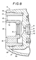
- a nozzle cap 5 comprises a nozzle body 5a an a lituid guide 5b.
- the liquid guide 5b is engaged fixedly with the end of a liquid injection cylinder 4.
- the nozzle body 5a has substantially triangular shape in the front shape.
- a nozzle port 6 is perforated at the center on the front face of the nozzle body 5a.
- the nozzle body 5a is rotatably engaged through a short cylindrical portion 5c with a plug 9 at the end of the liquid guide 5b.
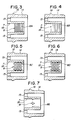
- Figs. 1 (A) and 1 (B) show "foaming" position of the nozzle cap.
- Shallow grooves 10 are formed at a plurality of peripheral positions on the peripheral surface of the end of the plug 9 of the liquid guide 5b in a longutudinal direction from the front end face over a predetermined zone.
- Liquid passages 11 are formed at a plurality of peripheral positions on the inner periphery of an end cylindrical portion 5c in longitudinal line direction from the rear end face over a predetermined zone.
- a spin groove 12 is disposed at the rear side face of the nozzle port 6.
- the shallow grooves 10, 10 communicate between the liquid passage 11, 11 and the spin groove 12 to thus inject high pressure liquid through the spin groove 12 and the nozzle port 6 in an atomized state to collide the atomized liquid to the inner peripheral wall of the foaming cylinder 7 to foam the liquid.
- the foaming cylinder 7 is integrally formed as an outer periphery thereof with a large-diameter mounting cylinder 13.
- the mounting cylinder 13 is engaged fixedly within a peripheral wall 14 projected toward the front face side so that the foaming cylinder 7 is arranged at an air gap 13A of suitable distance on the front face of the nozzle port 6 of the nozzle body 5a.
- the foaming cylinder 7 and the mounting cylinder 13 are integrated by a front end plate.
- Air intake openings 15 are perforated peripherally at the end plate and communicate with the air gap 13A.
- the foaming cylinder 7 also has an engaging projecting circumferential strip 16 formed on the outer peripheral surface of the mounting cylinder 13 to be engaged with an engaging inner circumferential groove 17 formed on the inner peripheral surface of the peripheral wall 14.
- the inner peripheral uneven portion 8 on the inner peripheral wall of the foaming cylinder 7 is formed substantially by half near the nozzle port 6 for colliding injecting liquid from the nozzle port 6 and the projecting strip is spirally projected on the inner wall to be formed in the uneven state.
- the inner peripheral uneven portion 8 of the foaming cylinder 7 may be formed in an uneven state on the inner wall of the foaming cylinder 7, and is not limited to the embodiment in Fig. 1.
- Fig. 2 to 7 show different examples of inner peripheral uneven portions 8 of the foaming cylinder 7.
- grooves are spirally recessed on the inner peripheral wall of the foaming cylinder 7 to form an uneven state on the inner peripheral wall.
- a plurality of ring-like projecting strips 8A are peripherally projected on the inner peripheral wall of the foaming cylinder 7 to form an uneven state on the inner peripheral wall.
- a plurality of ring-like peripheral grooves 8B are peripherally recessed on the inner peripheral wall of the foaming cylinder 7 to form an uneven state in the inner peripheral wall.
- a plurality of projections 8C are projected on the inner peripheral wall of the foaming cylinder 7 to form an uneven state on the inner peripheral wall.
- a plurality of pores 8D are recessed on the inner peripheral wall of the foaming cylinder 7 to form an uneven portion on the inner peripheral wall.
- small projections 8E of triangular projecting shape on a plane are formed at a predetermined circumferential interval on the inner peripheral wall of the foaming cylinder 7 to form an uneven state on the inner peripheral wall.
- an angle for diffusing liquid (atomized state) injected from the nozzle port 6 depends differently upon the viscosity of the liquid to be injected. Therefore, the formation of the uneven portion 8 is preferably devised on the basis of the viscosity of the liquid to be injected.
- the liquid is injected to be disperesed in a wide angel from the nozzle port 6.
- the injected liquid atomized state
- the foaming cylinders which have the uneven portions of the same shape are employed, a range that the low viscosity liquid is contacted with the uneven portion 8 becomes a peripheral surface near the nozzle port 6 on the inner peripheral wall of the foaming cylinder 7 as compared with that of the high viscosity liquid.
- the uneven portion 8 it is desirable to form the uneven portion 8 shorter and nearer to the nozzle port 6 axially as compared with the case of high viscosity liquid.
- the uneven portion 8 is formed too long in the axial direction in the foaming cylinder 7, the resistance of the uneven portion 8 against the liquid injected from the nozzle port 6 is increased so that the injecting pressure of the liquid injected from an injection port 18 decreases.
- the uneven portion 8 is formed on the portion near the side of the nozzle port 6 from the center of the inner peripheral wall of the foaming cylinder 7. When the foamability is good and the viscosity of the liquid is low, foaming is performed efficiently even if the uneven portion 8 is formed shorter in the axial direction of the foaming cylinder 7.
- the liquid is diffused and injected in a relatively narrow angle from the nozzle port 6 as compared with the case of low viscosity liquid.
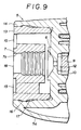
- the inner diameter of the portion 7a formed with no uneven portion 8 of the forming cylinder 7 may increased larger than the maximum inner diameter of the uneven portion 8.
- the atomizing pattern can be varied.
- the inner diameter of the portion 7a not formed with the uneven portion 8 of the foaming cylinder 7 may be formed smaller than the minimum inner diameter of the uneven portion 8.
- the resistance increases excessively to cause the injecting pressure of the liquid to reduce, thereby permitting the liquid to leak and drop from the injection port.
- the uneven portion 8 of the inner peripheral wall of the foaming cylinder 7 is formed mainly on the rear half portion near the nozzle port 6 on the inner peripheral wall of the foaming cylinder 7 and it is preferable not to form the uneven portion 8 on the entire inner peripheral wall of the foaming cylinder 7. If the uneven portion 8 is formed on the entire inner peripheral wall of the foaming cylinder 7, the resistance against the injected liquid by the uneven portion 8 is excessively increased to reduce the injection pressure of the liquid.
- the axial length of the uneven portion 8 on the inner peripheral surface depends upon the viscosity of the liquid.
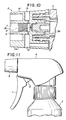
- the foaming cylinder 7 is formed independently from the nozzle body 5a.
- the foaming cylinder 7 may be formed integrally with the nozzle body 5a.
- Fig. 10 shows the example of this case.
- a foaming cylinder 7 is projected integrally from the front wall of the outer periphery of the nozzle port.
- the respective portions are molded of synthetic resin material.
- the uneven portion 8 is formed on the inner peripheral wall of the foaming cylinder 7 so that the injecting liquid from the nozzle port 6 is complicatedly reflected by the uneven portion 8. Therefore, the nozzle cap having high foaming efficiency can be provided.
Landscapes
- Nozzles (AREA)
- Closures For Containers (AREA)
Priority Applications (5)
| Application Number | Priority Date | Filing Date | Title |
|---|---|---|---|
| DE8787311456T DE3785454T2 (de) | 1987-12-24 | 1987-12-24 | Duesenkappe. |
| EP87311456A EP0322488B1 (fr) | 1987-12-24 | 1987-12-24 | Capuchon de buse |
| AU83099/87A AU606640B2 (en) | 1987-12-24 | 1987-12-29 | Nozzle cap |
| CA000556361A CA1330211C (fr) | 1987-12-24 | 1988-01-12 | Capuchon d'ajutage |
| US07/372,112 US4971252A (en) | 1987-12-24 | 1989-06-28 | Nozzle cap |
Applications Claiming Priority (2)
| Application Number | Priority Date | Filing Date | Title |
|---|---|---|---|
| EP87311456A EP0322488B1 (fr) | 1987-12-24 | 1987-12-24 | Capuchon de buse |
| CA000556361A CA1330211C (fr) | 1987-12-24 | 1988-01-12 | Capuchon d'ajutage |
Publications (2)
| Publication Number | Publication Date |
|---|---|
| EP0322488A1 true EP0322488A1 (fr) | 1989-07-05 |
| EP0322488B1 EP0322488B1 (fr) | 1993-04-14 |
Family
ID=25671660
Family Applications (1)
| Application Number | Title | Priority Date | Filing Date |
|---|---|---|---|
| EP87311456A Expired - Lifetime EP0322488B1 (fr) | 1987-12-24 | 1987-12-24 | Capuchon de buse |
Country Status (4)
| Country | Link |
|---|---|
| EP (1) | EP0322488B1 (fr) |
| AU (1) | AU606640B2 (fr) |
| CA (1) | CA1330211C (fr) |
| DE (1) | DE3785454T2 (fr) |
Cited By (3)
| Publication number | Priority date | Publication date | Assignee | Title |
|---|---|---|---|---|
| FR2660289A1 (fr) * | 1990-04-03 | 1991-10-04 | Oreal | Bouton-poussoir pour bidon aerosol, et bidon aerosol equipe d'un tel bouton-poussoir. |
| EP0554373A4 (fr) * | 1990-10-25 | 1994-02-02 | Contico International, Inc. | |
| US5622318A (en) * | 1993-11-03 | 1997-04-22 | Sofab | Spray nozzle for an aerosol dispenser |
Citations (3)
| Publication number | Priority date | Publication date | Assignee | Title |
|---|---|---|---|---|
| DE8434459U1 (de) * | 1984-11-24 | 1986-04-03 | Zeller Plastik Koehn, Graebner & Co, 5583 Zell | Schaumerzeuger |
| US4598862A (en) * | 1983-05-31 | 1986-07-08 | The Dow Chemical Company | Foam generating device and process |
| EP0237696A2 (fr) * | 1986-01-10 | 1987-09-23 | AFA Products, Inc. | Buse en deux parties pour générateur de mousse |
-
1987
- 1987-12-24 EP EP87311456A patent/EP0322488B1/fr not_active Expired - Lifetime
- 1987-12-24 DE DE8787311456T patent/DE3785454T2/de not_active Expired - Lifetime
- 1987-12-29 AU AU83099/87A patent/AU606640B2/en not_active Ceased
-
1988
- 1988-01-12 CA CA000556361A patent/CA1330211C/fr not_active Expired - Fee Related
Patent Citations (3)
| Publication number | Priority date | Publication date | Assignee | Title |
|---|---|---|---|---|
| US4598862A (en) * | 1983-05-31 | 1986-07-08 | The Dow Chemical Company | Foam generating device and process |
| DE8434459U1 (de) * | 1984-11-24 | 1986-04-03 | Zeller Plastik Koehn, Graebner & Co, 5583 Zell | Schaumerzeuger |
| EP0237696A2 (fr) * | 1986-01-10 | 1987-09-23 | AFA Products, Inc. | Buse en deux parties pour générateur de mousse |
Cited By (6)
| Publication number | Priority date | Publication date | Assignee | Title |
|---|---|---|---|---|
| FR2660289A1 (fr) * | 1990-04-03 | 1991-10-04 | Oreal | Bouton-poussoir pour bidon aerosol, et bidon aerosol equipe d'un tel bouton-poussoir. |
| EP0465275A1 (fr) * | 1990-04-03 | 1992-01-08 | L'oreal | Bouton-poussoir pour bidon aérosol, et bidon aérosol équipé d'un tel bouton-poussoir |
| US5139201A (en) * | 1990-04-03 | 1992-08-18 | L'oreal | Push-button for aerosol can, and aerosol can provided with a push-button of this kind |
| EP0554373A4 (fr) * | 1990-10-25 | 1994-02-02 | Contico International, Inc. | |
| USRE35744E (en) * | 1990-10-25 | 1998-03-17 | Contico International, Inc. | Spinner assembly for a sprayer |
| US5622318A (en) * | 1993-11-03 | 1997-04-22 | Sofab | Spray nozzle for an aerosol dispenser |
Also Published As
| Publication number | Publication date |
|---|---|
| EP0322488B1 (fr) | 1993-04-14 |
| AU606640B2 (en) | 1991-02-14 |
| DE3785454D1 (en) | 1993-05-19 |
| CA1330211C (fr) | 1994-06-14 |
| AU8309987A (en) | 1989-07-20 |
| DE3785454T2 (de) | 1993-07-29 |
Similar Documents
| Publication | Publication Date | Title |
|---|---|---|
| US4971252A (en) | Nozzle cap | |
| US4979646A (en) | Paste dispenser | |
| US4989790A (en) | Nozzle cap, spring valve and body assembly | |
| US4365751A (en) | Trigger type liquid injector | |
| KR100504082B1 (ko) | 수동펌프스프레이어 | |
| CN1305582C (zh) | 可伸缩的发泡剂喷嘴 | |
| US4247048A (en) | Dispensing nozzle | |
| US5335858A (en) | Pump sprayer having leak preventing seals and closures | |
| US4940186A (en) | Manually operated trigger type dispenser, a spinner for use in the dispenser, and a flow-pattern switching mechanism for use in the dispenser | |
| US4991778A (en) | Adjustable nozzle assembly | |
| US4953791A (en) | Manually operated trigger type dispenser, method of assembling the same, and a spinner for use in the dispenser | |
| US4911361A (en) | Manually operated trigger type dispenser, method of assembling the same, and a spinner for use in the dispenser | |
| KR900701408A (ko) | 트리거 스프레이어에 사용되는 배럴스크린 인서트를 구비한 거품노즐조립체 | |
| US5181658A (en) | Nozzle with incorporated valve | |
| EP0322488A1 (fr) | Capuchon de buse | |
| CA2475049A1 (fr) | Dispositif d' echantillons de parfum | |
| US4165824A (en) | Self cleaning shampoo dispenser | |
| JPH0634858Y2 (ja) | 液体の泡状噴射器のノズル | |
| JPH05104038A (ja) | 媒体用排出ノズル | |
| JPH0634857Y2 (ja) | 液体の泡状噴射器のノズル | |
| JP2915853B2 (ja) | トリガー式液体泡状噴射器 | |
| JPH0639809Y2 (ja) | 液体噴出器のノズル | |
| JP2811228B2 (ja) | 内燃機関用燃料噴射ノズル | |
| JPS6027482Y2 (ja) | トリガ−式液体噴出器のノズル | |
| JPS6027483Y2 (ja) | トリガ−式霧等噴出器のノズル |
Legal Events
| Date | Code | Title | Description |
|---|---|---|---|
| PUAI | Public reference made under article 153(3) epc to a published international application that has entered the european phase |
Free format text: ORIGINAL CODE: 0009012 |
|
| AK | Designated contracting states |
Kind code of ref document: A1 Designated state(s): CH DE FR GB IT LI NL |
|
| 17P | Request for examination filed |
Effective date: 19891221 |
|
| 17Q | First examination report despatched |
Effective date: 19910125 |
|
| GRAA | (expected) grant |
Free format text: ORIGINAL CODE: 0009210 |
|
| AK | Designated contracting states |
Kind code of ref document: B1 Designated state(s): CH DE FR GB IT LI NL |
|
| ITF | It: translation for a ep patent filed | ||
| REF | Corresponds to: |
Ref document number: 3785454 Country of ref document: DE Date of ref document: 19930519 |
|
| ET | Fr: translation filed | ||
| PLBE | No opposition filed within time limit |
Free format text: ORIGINAL CODE: 0009261 |
|
| STAA | Information on the status of an ep patent application or granted ep patent |
Free format text: STATUS: NO OPPOSITION FILED WITHIN TIME LIMIT |
|
| 26N | No opposition filed | ||
| PGFP | Annual fee paid to national office [announced via postgrant information from national office to epo] |
Ref country code: CH Payment date: 20010306 Year of fee payment: 14 |
|
| PGFP | Annual fee paid to national office [announced via postgrant information from national office to epo] |
Ref country code: FR Payment date: 20011212 Year of fee payment: 15 |
|
| PGFP | Annual fee paid to national office [announced via postgrant information from national office to epo] |
Ref country code: GB Payment date: 20011227 Year of fee payment: 15 |
|
| PG25 | Lapsed in a contracting state [announced via postgrant information from national office to epo] |
Ref country code: LI Free format text: LAPSE BECAUSE OF NON-PAYMENT OF DUE FEES Effective date: 20011231 Ref country code: CH Free format text: LAPSE BECAUSE OF NON-PAYMENT OF DUE FEES Effective date: 20011231 |
|
| REG | Reference to a national code |
Ref country code: GB Ref legal event code: IF02 |
|
| PGFP | Annual fee paid to national office [announced via postgrant information from national office to epo] |
Ref country code: DE Payment date: 20020109 Year of fee payment: 15 |
|
| REG | Reference to a national code |
Ref country code: CH Ref legal event code: PL |
|
| PG25 | Lapsed in a contracting state [announced via postgrant information from national office to epo] |
Ref country code: GB Free format text: LAPSE BECAUSE OF NON-PAYMENT OF DUE FEES Effective date: 20021224 |
|
| PGFP | Annual fee paid to national office [announced via postgrant information from national office to epo] |
Ref country code: NL Payment date: 20021227 Year of fee payment: 16 |
|
| PG25 | Lapsed in a contracting state [announced via postgrant information from national office to epo] |
Ref country code: DE Free format text: LAPSE BECAUSE OF NON-PAYMENT OF DUE FEES Effective date: 20030701 |
|
| GBPC | Gb: european patent ceased through non-payment of renewal fee |
Effective date: 20021224 |
|
| PG25 | Lapsed in a contracting state [announced via postgrant information from national office to epo] |
Ref country code: FR Free format text: LAPSE BECAUSE OF NON-PAYMENT OF DUE FEES Effective date: 20030901 |
|
| REG | Reference to a national code |
Ref country code: FR Ref legal event code: ST |
|
| PG25 | Lapsed in a contracting state [announced via postgrant information from national office to epo] |
Ref country code: NL Free format text: LAPSE BECAUSE OF NON-PAYMENT OF DUE FEES Effective date: 20040701 |
|
| NLV4 | Nl: lapsed or anulled due to non-payment of the annual fee |
Effective date: 20040701 |
|
| PG25 | Lapsed in a contracting state [announced via postgrant information from national office to epo] |
Ref country code: IT Free format text: LAPSE BECAUSE OF NON-PAYMENT OF DUE FEES;WARNING: LAPSES OF ITALIAN PATENTS WITH EFFECTIVE DATE BEFORE 2007 MAY HAVE OCCURRED AT ANY TIME BEFORE 2007. THE CORRECT EFFECTIVE DATE MAY BE DIFFERENT FROM THE ONE RECORDED. Effective date: 20051224 |