EP0322547B1 - Bouchon pour lyophilisation - Google Patents
Bouchon pour lyophilisation Download PDFInfo
- Publication number
- EP0322547B1 EP0322547B1 EP88118842A EP88118842A EP0322547B1 EP 0322547 B1 EP0322547 B1 EP 0322547B1 EP 88118842 A EP88118842 A EP 88118842A EP 88118842 A EP88118842 A EP 88118842A EP 0322547 B1 EP0322547 B1 EP 0322547B1
- Authority
- EP
- European Patent Office
- Prior art keywords
- bung
- transverse plane
- circumferential surface
- cams
- longitudinal axis
- Prior art date
- Legal status (The legal status is an assumption and is not a legal conclusion. Google has not performed a legal analysis and makes no representation as to the accuracy of the status listed.)
- Expired - Lifetime
Links
Images

Classifications
-
- B—PERFORMING OPERATIONS; TRANSPORTING
- B65—CONVEYING; PACKING; STORING; HANDLING THIN OR FILAMENTARY MATERIAL
- B65D—CONTAINERS FOR STORAGE OR TRANSPORT OF ARTICLES OR MATERIALS, e.g. BAGS, BARRELS, BOTTLES, BOXES, CANS, CARTONS, CRATES, DRUMS, JARS, TANKS, HOPPERS, FORWARDING CONTAINERS; ACCESSORIES, CLOSURES, OR FITTINGS THEREFOR; PACKAGING ELEMENTS; PACKAGES
- B65D51/00—Closures not otherwise provided for
- B65D51/24—Closures not otherwise provided for combined or co-operating with auxiliary devices for non-closing purposes
- B65D51/241—Closures not otherwise provided for combined or co-operating with auxiliary devices for non-closing purposes provided with freeze-drying means
-
- B—PERFORMING OPERATIONS; TRANSPORTING
- B01—PHYSICAL OR CHEMICAL PROCESSES OR APPARATUS IN GENERAL
- B01L—CHEMICAL OR PHYSICAL LABORATORY APPARATUS FOR GENERAL USE
- B01L3/00—Containers or dishes for laboratory use, e.g. laboratory glassware; Droppers
- B01L3/50—Containers for the purpose of retaining a material to be analysed, e.g. test tubes
- B01L3/508—Rigid containers without fluid transport within
- B01L3/5082—Test tubes per se
- B01L3/50825—Closing or opening means, corks, bungs
-
- B—PERFORMING OPERATIONS; TRANSPORTING
- B65—CONVEYING; PACKING; STORING; HANDLING THIN OR FILAMENTARY MATERIAL
- B65D—CONTAINERS FOR STORAGE OR TRANSPORT OF ARTICLES OR MATERIALS, e.g. BAGS, BARRELS, BOTTLES, BOXES, CANS, CARTONS, CRATES, DRUMS, JARS, TANKS, HOPPERS, FORWARDING CONTAINERS; ACCESSORIES, CLOSURES, OR FITTINGS THEREFOR; PACKAGING ELEMENTS; PACKAGES
- B65D39/00—Closures arranged within necks or pouring openings or in discharge apertures, e.g. stoppers
- B65D39/0005—Closures arranged within necks or pouring openings or in discharge apertures, e.g. stoppers made in one piece
- B65D39/0023—Plastic cap-shaped hollow plugs
-
- B—PERFORMING OPERATIONS; TRANSPORTING
- B65—CONVEYING; PACKING; STORING; HANDLING THIN OR FILAMENTARY MATERIAL
- B65D—CONTAINERS FOR STORAGE OR TRANSPORT OF ARTICLES OR MATERIALS, e.g. BAGS, BARRELS, BOTTLES, BOXES, CANS, CARTONS, CRATES, DRUMS, JARS, TANKS, HOPPERS, FORWARDING CONTAINERS; ACCESSORIES, CLOSURES, OR FITTINGS THEREFOR; PACKAGING ELEMENTS; PACKAGES
- B65D2539/00—Details relating to closures arranged within necks or pouring openings or in discharge apertures, e.g. stoppers
- B65D2539/001—Details of closures arranged within necks or pouring opening or in discharge apertures, e.g. stoppers
- B65D2539/005—Details of closures arranged within necks or pouring opening or in discharge apertures, e.g. stoppers provided with slits or gaps for increasing the elasticity
Definitions
- the invention relates to a freeze-drying stopper made of rubber-elastic material, consisting of a substantially cylindrical outer circumferential surface intended for insertion into the container neck to be sealed, with a pin and an integral part of it, defining a first transverse plane with the lower boundary surface of its radially projecting edge.
- the peg containing a cavity which surrounds the peg longitudinal axis and is open to the free peg end face and extends substantially over the entire peg length and which extends to the peripheral surface of the peg via at least one slot extending in the direction of the peg longitudinal axis is open, which starts from the free end face of the spigot and extends up to a perpendicular to the longitudinal axis of the spigot, roughly approximating the free spigot length of the second transverse plane and the spigot projecting over the circumferential surface exercises, the axially outer boundaries of which lie on a common third transverse plane perpendicular to the longitudinal axis of the journal, which extends between the second transverse plane and the free journal front side and in each case at a distance therefrom.
- Freeze-drying stoppers of this type are known (FR-A-2 096 680: Fig. 7-12) and have a spigot, the cavity of which faces the lateral peripheral surface is open via two slots that are diametrically opposed.
- the projections protruding from the lateral circumferential surface, which define a stable intermediate position when the plug is partially pressed into the container neck, are formed by a first annular bead which has the shape of a triangle in cross section and which lies with its sharp outer edge in the third transverse plane.
- the ring bead extends, apart from the interruptions caused by the two slots, over the entire outer peripheral surface of the pin.
- a second, in principle identically formed ring bead of greater axial extent and somewhat smaller diameter the sole located between the two ring beads having a diameter which is essentially the diameter of the outer cylindrical peripheral surface of the Cone corresponds.
- the plug of the stopper is only partially pressed in to a first position, which is defined by the elevations or the first annular bead resting on the end face of the container neck.
- a first position which is defined by the elevations or the first annular bead resting on the end face of the container neck.
- the interior of the container is still connected to its surroundings via the slots, so that vapors and gases can escape during freeze-drying.
- the stopper is pushed in completely by means of a mechanical device, ie brought into a second position in which the first cylindrical section of the journal, which is not interrupted by the slots, brings about the complete sealing.
- a first type of tube made of tubular glass in which the neck is completely cylindrical on the inside
- a second type known as a glassworks container
- the neck also has a cylindrical shape over most of its length receiving the stopper is, but has a blow back directly at the transition to the neck end face, which appears as a small, radially inwardly protruding ridge.
- the ridge causes greater press-in forces.
- the linear stability of the ridge reduces the stability of the stopper in the first position mentioned.
- the known freeze-drying stopper has in the first press-in position in glassworks containers by snapping the burr between a stable position for the two ring beads. With further pressing for the purpose of transferring to the second press-in position, however, relatively strong forces have to be applied, the two pin parts separated by the slots being bent radially inwards and the resulting deformation continuing into the sealing surface of the pin.
- the object of the invention is to develop a container made of tubular glass for the same neck nominal diameter and freeze-drying stoppers of the type mentioned at the outset that can be used for glassworks containers in such a way that it has advantageous properties in both applications, in particular with regard to material requirements, simple machinability, tight fit the closed position with low press-in force.
- the pin has only one slot, that the elevations are formed by a plurality of spaced cams, that in the axial portion of the outer circumferential surface between the third transverse plane delimiting the cams axially and the is located free pin end face, a groove extending in a fourth transverse plane perpendicular to the longitudinal axis of the pin is formed, the distance of the axially inner side wall of the groove from the third transverse plane being less than the axial width of the groove.
- the cross-sectional area of the pin cavity is also increased in a desired manner, which is particularly important for the removal of the container contents by means of a cannula.
- the cams which are spaced apart, have a smaller material volume compared to continuous ring beads. When the plug is fully pressed in, supported by the immediately adjacent groove, the material of the cams can be displaced relatively easily into the surrounding area, so that the bending of the pin is reduced and thereby also deformations in the area adjacent to the plug flange avoid the cylindrical peripheral surface, which is decisive for the tightness of the stopper.
- the axially inner sidewall of the groove lies in the third transverse plane, i.e. represents a radially inner extension of the axially outer limits of the cams.
- the axial width of the groove, as well as its depth, is advantageously at least 0.8 mm.
- three cams are provided, one cam of which is diametrically opposite the slot, the center of which lies in a first longitudinal plane containing the longitudinal axis of the pin and running through the center of the slot, and that the centers of the other two cams each contain the longitudinal axis of the pin second and third longitudinal planes are arranged which enclose angles of more than 90 ° of equal size with the first longitudinal plane, the cams being designed as elongated beads, the length of which in the circumferential direction is at least 2.5 times their axial extent.
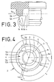
- the freeze-drying stopper is shown in FIGS. 1 to 4 in a magnification of approximately 5 times. It is made of rubber and contains a pin 1 intended for insertion into the container neck to be closed and a flange 2 formed in one piece with it.
- the pin 1 has, in addition to its special design which will be explained in the following, in principle the shape of a hollow cylinder which delimits a cavity 4 which is open to the free pin end face 3.
- the flange 2 has an edge 2a projecting laterally over the pin 1, on which a lower edge extending radially outward from the pin flat annular boundary surface 5 is formed.
- This boundary surface lies in a first transverse plane Q 1 penetrated perpendicularly by the longitudinal axis A of the pin, is intended for bearing against the end face of the neck of the container and limits the insertion depth of the pin in its closed position.
- the closed central wall part 2b of the flange 2 delimits the cavity 4 axially with an inner wall surface 6 which is flat in a surface area surrounding the journal longitudinal axis A and lies in a transverse plane P which runs at a short distance from the first transverse plane Q 1.
- the outer surface 7 of the flange 2 facing away from the peg 1 has two projections 8 each running approximately semicircularly, the diameter of which is small with respect to the outer diameter of the flange and which mark a surface area surrounding the longitudinal axis A of the pin intended for the puncture of a withdrawal cannula. From the surface area of the outer surface 7 surrounding the projections 8, further projections 9 extend radially to the longitudinal axis A of the pin and at equal angular intervals, which prevent freeze-drying stoppers lying against one another with their outer surfaces from adhering to one another or to other objects and thereby hinder their processing.
- the pin 1 In a first section Z1 of its axial length, which is located between the first transverse plane Q1 and a perpendicular to the longitudinal axis A, the pin length in a rough approximation centrally dividing second transverse plane Q2, the pin 1 is of full-walled design, ie it has a closed outer upper peripheral surface 10a.
- This peripheral surface is adjacent to the first transverse plane Q 1 narrow and flat annular recess 10 'and an adjoining, axially longer cylindrical surface is formed, the latter having a diameter D which is slightly larger than the inside diameter of the neck of the container and, when the plug is fully inserted, rests sealingly against the neck of the container under elastic prestress.
- a second section Z2 of the axial length of the pin 1, which extends from the second transverse plane Q2 to the free pin end face 3, has an outer cylindrical envelope surface 10b, which has essentially the same diameter D as the upper peripheral surface 10a.
- the passage 11 has the shape of a slot and contains two side surfaces 12a, 12b, which are substantially flat, run almost parallel to the longitudinal axis A of the pin, widen from the cavity 4 to the mouth 13 and have a mutual average distance which is approximately the average diameter of the Cavity corresponds.
- a first inner part 12c of the bottom surface of the passage 11 lies in a plane parallel to the second transverse plane Q2 and in this respect offset by a small distance from the end face 3 of the pin.
- the inner part 12c is followed by an outer part 12d of the bottom surface which is shaped in the form of a sector of a truncated cone and which, with an edge located in the second transverse plane Q2 and forming part of the mouth 13, merges into the peripheral surface 10b.
- cams 14a-14c When the pin 1 is inserted into the container neck, these cams 14a-14c cause an inhibition by the abutment of their delimitations 15 on the end face of the container neck and define a first position of the stopper in which it is already non-positively connected by elastic deformation of the pin part adjoining the pin end face is held in the container neck, but the interior of the container is still open to the environment via the passage 11. Vapors and gases can therefore escape from the material contained in the container during freeze drying to the surroundings of the container.
- the cams 14a-14c are pushed back by the increased application of force to the plug, the cams themselves and the material of the pin 1 surrounding them being deformed.
- the pin can then be inserted into the container neck up to a second position (closed position), which is defined by contact of the boundary surface 5 of the flange 2 on the end face of the container neck and in which the first section Z 1 of the pin equipped with the closed upper peripheral surface 10 a a complete seal of the container neck causes.
- the cams 14a-14c each have the shape of semicircular, elongated beads in cross-section, which extend in the circumferential direction of the pin 1, their length in this direction in each case being at least 2.5 times their axial extent.
- a first cam 14a is arranged diametrically opposite the passage (slot) 11 such that its center lies in a first longitudinal plane L1, which contains the pin longitudinal axis A and passes through the middle between the side surfaces 12a, 12b of the passage 11.
- the centers of the other two cams 14b, 14c are defined by a second longitudinal plane L2 or third longitudinal plane L3, which contain the pin longitudinal axis A containing on different sides of the first longitudinal plane L1 and with this each have the same angle ⁇ 2 or ⁇ 3 of Include approx. 110 ° (old degree).
- a groove 16 is arranged in such a way that its inner (ie adjacent to the flange 2) side wall lies in the third transverse plane Q3.
- the groove 16 is adjoined by a peripheral surface 17 of the pin 1, the diameter of which is slightly larger than the diameter of the peripheral surface from which the cams 14a-14c project. The peripheral surface closes via one of the easier insertion of the pin 1 into the container neck conical surface 18 on the pin end face.
- the inner wall surface 6 axially delimiting the cavity 4 of the peg 1 merges via a rounded fillet into a laterally delimiting inner wall surface 19 which has the shape of a truncated cone, the axis of which is the longitudinal axis A of the peg and its largest diameter is on the Has end face 3.
Landscapes
- Health & Medical Sciences (AREA)
- Chemical & Material Sciences (AREA)
- Engineering & Computer Science (AREA)
- Mechanical Engineering (AREA)
- Analytical Chemistry (AREA)
- General Health & Medical Sciences (AREA)
- Hematology (AREA)
- Clinical Laboratory Science (AREA)
- Chemical Kinetics & Catalysis (AREA)
- Closures For Containers (AREA)
Claims (8)
- Bouchon de lyophilisation en matière élastique caoutchouteuse constitué d'un tourillon (1) destiné à être introduit dans le goulot du récipient à boucher, présentant une face périphérique externe (10a, 10b, 17) sensiblement cylindrique et, moulé d'une seule pièce avec ledit bouchon (1), d'un flasque (2) de forme sensiblement circulaire définissant, avec la face de délimitation inférieure (5) de son bord (2a) se projetant radialement, un premier plan transversal (Q₁), ledit tourillon (1) entourant une cavité (4) située autour de l'axe longitudinal (A) dudit tourillon, ouvert vers le côté frontal libre (3) de ce tourillon et s'étendant sensiblement sur toute la longueur de celui-ci, ladite cavité (4) étant ouverte en direction de la face périphérique (10a, 10b, 17) du tourillon (1) par au moins une fente (11) s'étendant en direction de l'axe longitudinal (A) du tourillon, et partant du côté frontal libre (3) de ce tourillon en s'étendant jusqu'à un deuxième plan transversal (Q₂) perpendiculaire à l'axe longitudinal (A) et partageant très approximativement en deux la longueur libre du tourillon, ledit tourillon (1) présentant sur la face périphérique (10a, 10b, 17) des projections (14a à 14c) dont les limites axiales extérieures sont situées dans un troisième plan transversal commun (Q₃), perpendiculaire à l'axe longitudinal (A) du tourillon, ce plan s'étendant entre le deuxième plan transversal (Q₂) et le côté frontal libre (3) du tourillon et à une certaine distance de ces plans, caractérisé par le fait que le tourillon (1) ne présente qu'une fente (11), par le fait que les projections sont constituées d'une pluralité de cames (14a, 14b, 14c) disposées à une certaine distance les unes des autres, par le fait que dans la section axiale de la face périphérique extérieure (17) située entre le troisième plan transversal (Q₃) délimitant axialement vers l'extérieur les cames (14a, 14b, 14c) et le côté frontal libre (3) du tourillon, est formée une rainure (16) s'étendant dans un quatrième plan transversal (Q₄) perpendiculaire à l'axe longitudinal (A) du tourillon, la distance entre la paroi latérale, axialement interne, de la rainure (16) et le troisième plan transversal (Q₃) étant inférieure à la largeur axiale (W) de ladite rainure (16).
- Bouchon de lyophilisation selon la revendication 1, caractérisé par le fait que la paroi latérale axialement interne de la rainure (16) est située dans le troisième plan transversal (Q₃)
- Bouchon de lyophilisation selon la revendication 1, caractérisé par le fait que la largeur axiale (W) de la rainure (16) est égale à au moins 0,8 mm.
- Bouchon de lyophilisation selon la revendication 1, caractérisé par le fait que la rainure (16) présente une profondeur (T) d'au moins 0,8 mm.
- Bouchon de lyophilisation selon la revendication 1, caractérisé par le fait que trois cames (14a, 14b 14c) sont prévues dont une came (14a) fait diamétralement face à la fente, son centre étant situé dans un premier plan longitudinal (L₁) contenant l'axe longitudinal (A) du tourillon s'étendant à travers le centre de la fente, et par le fait que les centres des deux autres cames (14b, 14c) sont disposés respectivement dans les deuxième et troisième plans longitudinaux (L₂, L₃) contenant l'axe longitudinal (A) du tourillon, ces plans formant avec le premier plan longitudinal (L₁) des angles égaux (α₂, α₃) supérieurs à 90°.
- Bouchon de lyophilisation selon la revendication 1 ou 5, caractérisé par le fait que les cames (14a, 14b, 14c) sont réalisées sous la forme de bourrelets allongés dont la longueur dans le sens périphérique est au moins égale à 2,5 fois son extension axiale.
- Bouchon de lyophilisation selon la revendication 1, caractérisé par le fait que le diamètre de la section axiale de la face périphérique externe du tourillon (1) située entre la rainure (16) et le côté frontal libre dudit tourillon est légèrement supérieur au diamètre de la section axiale située entre les cames (14a, 14b, 14c).
- Bouchon de lyophilisation selon la revendication 1, caractérisé par le fait que la face périphérique externe du tourillon (1) présente une encoche (10') de forme annulaire, étroite et plate, immédiatement adjacente au premier plan transversal (Q₁).
Priority Applications (1)
| Application Number | Priority Date | Filing Date | Title |
|---|---|---|---|
| AT88118842T ATE78781T1 (de) | 1987-12-24 | 1988-11-11 | Gefriertrocknungs-stopfen. |
Applications Claiming Priority (2)
| Application Number | Priority Date | Filing Date | Title |
|---|---|---|---|
| DE3744173 | 1987-12-24 | ||
| DE19873744173 DE3744173A1 (de) | 1987-12-24 | 1987-12-24 | Gefriertrocknungs-stopfen |
Publications (2)
| Publication Number | Publication Date |
|---|---|
| EP0322547A1 EP0322547A1 (fr) | 1989-07-05 |
| EP0322547B1 true EP0322547B1 (fr) | 1992-07-29 |
Family
ID=6343656
Family Applications (1)
| Application Number | Title | Priority Date | Filing Date |
|---|---|---|---|
| EP88118842A Expired - Lifetime EP0322547B1 (fr) | 1987-12-24 | 1988-11-11 | Bouchon pour lyophilisation |
Country Status (3)
| Country | Link |
|---|---|
| EP (1) | EP0322547B1 (fr) |
| AT (1) | ATE78781T1 (fr) |
| DE (2) | DE3744173A1 (fr) |
Families Citing this family (1)
| Publication number | Priority date | Publication date | Assignee | Title |
|---|---|---|---|---|
| US5845797A (en) * | 1996-07-31 | 1998-12-08 | Daikyo Seiko, Ltd. | Rubber plug for drug vessel |
Family Cites Families (4)
| Publication number | Priority date | Publication date | Assignee | Title |
|---|---|---|---|---|
| US3136440A (en) * | 1963-06-25 | 1964-06-09 | Becton Dickinson Co | Self sealing pierceable stopper for sealed containers |
| FR2096680B1 (fr) * | 1970-05-29 | 1973-12-21 | Barville Jean | |
| FR2416848A1 (fr) * | 1978-02-08 | 1979-09-07 | Rumpler Jean Jacques | Bouchon de recipient de produits medicamenteux |
| FR2432449A1 (fr) * | 1978-08-01 | 1980-02-29 | Coulter Electronics | Bouchon de fermeture pour une fiole |
-
1987
- 1987-12-24 DE DE19873744173 patent/DE3744173A1/de not_active Withdrawn
-
1988
- 1988-11-11 AT AT88118842T patent/ATE78781T1/de not_active IP Right Cessation
- 1988-11-11 DE DE8888118842T patent/DE3873297D1/de not_active Expired - Fee Related
- 1988-11-11 EP EP88118842A patent/EP0322547B1/fr not_active Expired - Lifetime
Also Published As
| Publication number | Publication date |
|---|---|
| EP0322547A1 (fr) | 1989-07-05 |
| ATE78781T1 (de) | 1992-08-15 |
| DE3744173A1 (de) | 1989-07-06 |
| DE3873297D1 (de) | 1992-09-03 |
Similar Documents
| Publication | Publication Date | Title |
|---|---|---|
| EP0322548B1 (fr) | Bouchon pour lyophilisation | |
| EP0128525B1 (fr) | Fermeture pour récipients, en particulier pour tubes, et ses applications | |
| DE3509641C2 (fr) | ||
| EP0399234B1 (fr) | Ampoule | |
| DE69624069T2 (de) | Flasche mit einem Henkel und Verfahren zur Herstellung der Flasche durch Streckblasformen | |
| EP1094974B1 (fr) | Clapet de fermeture a fente pour ouvertures de recipients | |
| DE1804549A1 (de) | Sicherheitsverschluss fuer Behaelter | |
| EP1192964B1 (fr) | Seringue avec réservoir cylindrique et capuchon de fermeture | |
| CH637345A5 (de) | Flaschenverschluss zur tropfenweisen entnahme einer sterilen fluessigkeit. | |
| EP0081124B1 (fr) | Fermeture pour récipient | |
| DE102011050983A1 (de) | Verschlussstopfen für pharmazeutische Anwendungen | |
| EP0322547B1 (fr) | Bouchon pour lyophilisation | |
| EP3002228B1 (fr) | Bouteille muni d'un bouchon de bouteille | |
| DE19613035B4 (de) | System mit einer Spritze und einem Griffstück | |
| AT504003B1 (de) | Universelle verschlussvorrichtung | |
| EP3288843B1 (fr) | Récipient comportant deux sections d'étanchéité | |
| DE2950242A1 (de) | Duennwandige kunststoff-flasche | |
| DE3418530A1 (de) | Vorrichtung zum verstopfen von behaeltern mit einem hals | |
| DE1164864B (de) | Flaschenverschluss | |
| EP0215202B1 (fr) | Procédé pour la fabrication d'un couvercle en matière synthétique pour récipients en forme de bouteille | |
| DE2426759A1 (de) | Kappenverschluss fuer flaschen | |
| EP0413245B1 (fr) | Casier à bouteilles utilisable verticalement et horizontalement | |
| DE2530232A1 (de) | Kippduese | |
| CH591372A5 (en) | Elastic material bottle sealing cap - has notches in edge engaging under bead either side of opening lug | |
| DE2313482A1 (de) | Verschlusskappe fuer tuben |
Legal Events
| Date | Code | Title | Description |
|---|---|---|---|
| PUAI | Public reference made under article 153(3) epc to a published international application that has entered the european phase |
Free format text: ORIGINAL CODE: 0009012 |
|
| AK | Designated contracting states |
Kind code of ref document: A1 Designated state(s): AT BE CH DE FR GB IT LI LU NL SE |
|
| 17P | Request for examination filed |
Effective date: 19891213 |
|
| 17Q | First examination report despatched |
Effective date: 19910415 |
|
| GRAA | (expected) grant |
Free format text: ORIGINAL CODE: 0009210 |
|
| AK | Designated contracting states |
Kind code of ref document: B1 Designated state(s): AT BE CH DE FR GB IT LI LU NL SE |
|
| REF | Corresponds to: |
Ref document number: 78781 Country of ref document: AT Date of ref document: 19920815 Kind code of ref document: T |
|
| REF | Corresponds to: |
Ref document number: 3873297 Country of ref document: DE Date of ref document: 19920903 |
|
| GBT | Gb: translation of ep patent filed (gb section 77(6)(a)/1977) | ||
| ITF | It: translation for a ep patent filed | ||
| ET | Fr: translation filed | ||
| PG25 | Lapsed in a contracting state [announced via postgrant information from national office to epo] |
Ref country code: LU Free format text: LAPSE BECAUSE OF NON-PAYMENT OF DUE FEES Effective date: 19921130 |
|
| PLBE | No opposition filed within time limit |
Free format text: ORIGINAL CODE: 0009261 |
|
| STAA | Information on the status of an ep patent application or granted ep patent |
Free format text: STATUS: NO OPPOSITION FILED WITHIN TIME LIMIT |
|
| 26N | No opposition filed | ||
| PGFP | Annual fee paid to national office [announced via postgrant information from national office to epo] |
Ref country code: CH Payment date: 19941110 Year of fee payment: 7 |
|
| PGFP | Annual fee paid to national office [announced via postgrant information from national office to epo] |
Ref country code: SE Payment date: 19941118 Year of fee payment: 7 |
|
| PGFP | Annual fee paid to national office [announced via postgrant information from national office to epo] |
Ref country code: NL Payment date: 19941130 Year of fee payment: 7 Ref country code: AT Payment date: 19941130 Year of fee payment: 7 |
|
| PGFP | Annual fee paid to national office [announced via postgrant information from national office to epo] |
Ref country code: BE Payment date: 19941212 Year of fee payment: 7 |
|
| EAL | Se: european patent in force in sweden |
Ref document number: 88118842.9 |
|
| PGFP | Annual fee paid to national office [announced via postgrant information from national office to epo] |
Ref country code: GB Payment date: 19951108 Year of fee payment: 8 |
|
| PG25 | Lapsed in a contracting state [announced via postgrant information from national office to epo] |
Ref country code: AT Effective date: 19951111 |
|
| PG25 | Lapsed in a contracting state [announced via postgrant information from national office to epo] |
Ref country code: SE Effective date: 19951112 |
|
| PG25 | Lapsed in a contracting state [announced via postgrant information from national office to epo] |
Ref country code: LI Effective date: 19951130 Ref country code: CH Effective date: 19951130 Ref country code: BE Effective date: 19951130 |
|
| BERE | Be: lapsed |
Owner name: HELVOET PHARMA N.V. Effective date: 19951130 |
|
| PG25 | Lapsed in a contracting state [announced via postgrant information from national office to epo] |
Ref country code: NL Effective date: 19960601 |
|
| REG | Reference to a national code |
Ref country code: CH Ref legal event code: PL |
|
| NLV4 | Nl: lapsed or anulled due to non-payment of the annual fee |
Effective date: 19960601 |
|
| EUG | Se: european patent has lapsed |
Ref document number: 88118842.9 |
|
| PG25 | Lapsed in a contracting state [announced via postgrant information from national office to epo] |
Ref country code: GB Effective date: 19961111 |
|
| GBPC | Gb: european patent ceased through non-payment of renewal fee |
Effective date: 19961111 |
|
| PGFP | Annual fee paid to national office [announced via postgrant information from national office to epo] |
Ref country code: FR Payment date: 19980928 Year of fee payment: 11 |
|
| PGFP | Annual fee paid to national office [announced via postgrant information from national office to epo] |
Ref country code: DE Payment date: 19991115 Year of fee payment: 12 |
|
| PG25 | Lapsed in a contracting state [announced via postgrant information from national office to epo] |
Ref country code: FR Free format text: LAPSE BECAUSE OF NON-PAYMENT OF DUE FEES Effective date: 20000731 |
|
| REG | Reference to a national code |
Ref country code: FR Ref legal event code: ST |
|
| PG25 | Lapsed in a contracting state [announced via postgrant information from national office to epo] |
Ref country code: DE Free format text: LAPSE BECAUSE OF NON-PAYMENT OF DUE FEES Effective date: 20010801 |
|
| PG25 | Lapsed in a contracting state [announced via postgrant information from national office to epo] |
Ref country code: IT Free format text: LAPSE BECAUSE OF NON-PAYMENT OF DUE FEES;WARNING: LAPSES OF ITALIAN PATENTS WITH EFFECTIVE DATE BEFORE 2007 MAY HAVE OCCURRED AT ANY TIME BEFORE 2007. THE CORRECT EFFECTIVE DATE MAY BE DIFFERENT FROM THE ONE RECORDED. Effective date: 20051111 |