EP0322552A2 - Dispositif de test de demi-produits - Google Patents
Dispositif de test de demi-produits Download PDFInfo
- Publication number
- EP0322552A2 EP0322552A2 EP88119186A EP88119186A EP0322552A2 EP 0322552 A2 EP0322552 A2 EP 0322552A2 EP 88119186 A EP88119186 A EP 88119186A EP 88119186 A EP88119186 A EP 88119186A EP 0322552 A2 EP0322552 A2 EP 0322552A2
- Authority
- EP
- European Patent Office
- Prior art keywords
- coil arrangement
- test
- test coil
- signal voltages
- ferromagnetic
- Prior art date
- Legal status (The legal status is an assumption and is not a legal conclusion. Google has not performed a legal analysis and makes no representation as to the accuracy of the status listed.)
- Granted
Links
- 238000012360 testing method Methods 0.000 title claims abstract description 59
- 230000005294 ferromagnetic effect Effects 0.000 claims abstract description 18
- 239000000463 material Substances 0.000 claims abstract description 13
- 230000005415 magnetization Effects 0.000 claims abstract description 12
- 239000002245 particle Substances 0.000 claims abstract description 10
- 230000005291 magnetic effect Effects 0.000 claims description 17
- 238000005516 engineering process Methods 0.000 claims description 3
- 230000000694 effects Effects 0.000 claims 1
- 238000011144 upstream manufacturing Methods 0.000 claims 1
- 230000007547 defect Effects 0.000 abstract description 11
- 238000000034 method Methods 0.000 abstract description 7
- 238000011156 evaluation Methods 0.000 abstract 1
- 239000003302 ferromagnetic material Substances 0.000 description 8
- 239000011265 semifinished product Substances 0.000 description 6
- 230000006698 induction Effects 0.000 description 4
- 239000002184 metal Substances 0.000 description 4
- 229910052751 metal Inorganic materials 0.000 description 4
- 230000005284 excitation Effects 0.000 description 3
- 230000004907 flux Effects 0.000 description 3
- 238000010586 diagram Methods 0.000 description 2
- 238000000053 physical method Methods 0.000 description 2
- 239000000047 product Substances 0.000 description 2
- 238000007493 shaping process Methods 0.000 description 2
- 238000004804 winding Methods 0.000 description 2
- 230000015572 biosynthetic process Effects 0.000 description 1
- 239000002131 composite material Substances 0.000 description 1
- 238000001514 detection method Methods 0.000 description 1
- 230000002500 effect on skin Effects 0.000 description 1
- 238000003780 insertion Methods 0.000 description 1
- 230000037431 insertion Effects 0.000 description 1
- 238000004519 manufacturing process Methods 0.000 description 1
- 150000002739 metals Chemical class 0.000 description 1
- 230000003287 optical effect Effects 0.000 description 1
- 230000000149 penetrating effect Effects 0.000 description 1
- 230000035515 penetration Effects 0.000 description 1
- 230000035699 permeability Effects 0.000 description 1
- 238000009420 retrofitting Methods 0.000 description 1
- 238000005096 rolling process Methods 0.000 description 1
- 238000000926 separation method Methods 0.000 description 1
- 230000011664 signaling Effects 0.000 description 1
Images
Classifications
-
- G—PHYSICS
- G01—MEASURING; TESTING
- G01N—INVESTIGATING OR ANALYSING MATERIALS BY DETERMINING THEIR CHEMICAL OR PHYSICAL PROPERTIES
- G01N27/00—Investigating or analysing materials by the use of electric, electrochemical, or magnetic means
- G01N27/72—Investigating or analysing materials by the use of electric, electrochemical, or magnetic means by investigating magnetic variables
- G01N27/82—Investigating or analysing materials by the use of electric, electrochemical, or magnetic means by investigating magnetic variables for investigating the presence of flaws
- G01N27/90—Investigating or analysing materials by the use of electric, electrochemical, or magnetic means by investigating magnetic variables for investigating the presence of flaws using eddy currents
- G01N27/9046—Investigating or analysing materials by the use of electric, electrochemical, or magnetic means by investigating magnetic variables for investigating the presence of flaws using eddy currents by analysing electrical signals
Definitions
- the invention relates to a device for testing elongated non-ferromagnetic metallic test material according to the preamble of claim 1. It is known that such devices have long been used to test a variety of semi-finished products, such as wires, rods, pipes. In particular, such tests take place after the test material has undergone shaping processing, for example in a rolling mill or the like. The test makes it possible to find cracks, cavities, overrolls, shells and other defects as far as these are located on or immediately below the surface of the test material.
- Inclusions made of ferromagnetic material play a special role in the sought-after defects, on the one hand because their occurrence indicates defects in the shaping tools, for example on signs of wear on rollers whose chipping particles have been rolled into the semi-finished product, and on the other hand because inclusions made of ferromagnetic Material in the further processing of metallic semifinished products can give rise to serious errors and, particularly when the semifinished product is being drawn to ever smaller diameters, inevitably cause splits, breaks and the like, and can even lead to damage to the drawing tool.
- the solution according to the invention makes it possible to use two different physical methods in a common device, which has been supplemented to the known by only a few simple means.
- the test coil arrangement and the means for evaluating the signal voltages can be used together for both methods.
- the use of only one test coil arrangement for both the eddy current and the induction process proves to be particularly advantageous when it comes to retrofitting in an existing production line, where the insertion of two test coil arrangements can often be difficult, if not impossible, for space reasons.
- the first and second signal voltages are separated from one another by a low-pass filter.
- a common preamplifier is used for the first and second signal voltages.
- a further embodiment of the invention consists in that a magnet yoke which is customary in eddy current testing technology is used as magnetizing means and is otherwise only used for the magnetic saturation of ferromagnetic test parts.
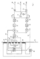
- the block diagram according to FIG. 1 contains a device, known per se, for testing metals using the eddy current method.
- This consists of an alternating current generator 10 with a switchable frequency, a test coil arrangement 12, the input 14 of which is fed by the generator 10 with an alternating current of the selected frequency, a preamplifier 18 which is connected to the output 16 of the test coil arrangement 12, one via line 20 from the generator 10 controlled phase-selective rectifier 22, the signal voltage de generated in the test coil arrangement 12 and amplified by the preamplifier 18 modulated, a filter arrangement 24 in which undesired components of the signal voltage are suppressed and a signal voltage threshold 26 which, when the signal voltage exceeds a certain threshold voltage, gives rise to a binary signal at its output 28.
- the test coil arrangement 12 has two excitation coils 30 and two receiver coils 32, each of which is passed through by the test material, a wire 34 made of non-ferromagnetic metal.
- the alternating current flowing from the generator 10 in the excitation coils 30 builds up an alternating magnetic field which penetrates the wire 34 and causes eddy currents in it. These in turn result in magnetic fields that induce 32 voltages in the receiver coils. Since the latter two are connected in series in the opposite direction of winding, the voltages induced in them stand out as long as there are no surface defects in the wire 34 to be examined. Surface defects of the wire 34 passing through the coil arrangement 12 influence the formation of the eddy currents and thus cause voltage changes in the receiver coils 32 which do not stand out because they occur at different times in the two coils. With a corresponding size of such an error, the associated signal voltage exceeds the threshold voltage in the signal voltage threshold 26, so that a binary signal is generated at its output 28.
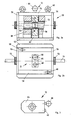
- FIGS. 2a, 2b and 3 show magnetization yoke 50 with built-in test coil arrangement 12 in a partially sectioned side view or in plan view
- FIG. 3 shows test coil arrangement 12 separately in a side view.
- the housing of the magnetization yoke 50 is composed of a base plate 52, a cover plate 54, two side plates 56 and two wall plates 58, each made of ferromagnetic material. Two support lugs 60 fastened to the cover plate 54 are used for transportation.
- an opening 62 On both sides of an opening 62 there are two magnetization coils 38 which are electrically connected in series and are connected to a direct current source 36.
- the test coil assembly 12 In the opening 62, their Continued in a recess in the cover plate 54, the test coil assembly 12 is inserted.
- the latter consists of a housing 64, a handle 66, a connecting socket 68 and a coil body 70 with four winding joints incorporated therein, in which the excitation coils 30 and the receiver coils 32 are embedded. As already described above, these are connected to one another and connected to the generator 10 or the input of the amplifier 18 via the connecting socket 68 and a cable (not shown).
- interchangeable guide nozzles 72 made of ferromagnetic material, which serve two purposes.
- they are available in different bore diameters adapted to the respective diameter of the wire 34.
- the receiver coils 32 perform an additional task.
- the ferromagnetic particles enclosed in the wire 34 and passing through the coils 32 are magnetized by the magnetic field of the magnetizing coils 38 and cause magnetic flux changes which induce a signal voltage in the coils 32.
- a simple coil 32 is sufficient for this.
- the use of two coils with the same structure, which are connected in different ways, has the advantage that voltages caused by interference fields, e.g. B. of interference fields of the supply network, stand out in the two coils 32.
- ferromagnetic particles induce 32 signal voltages of opposite polarity in the two coils at different times, which occur as a composite signal voltage at the terminals 16.
- a magnetization yoke with one or more can also be used Permanent magnets are used to generate the required constant magnetic field.
- Permanent magnets are used to generate the required constant magnetic field.
- the signal voltages at the terminals 16 of the test coil arrangement 12, that is to say both those based on eddy currents and those based on simple induction, are amplified together in the preamplifier 18.
- the output of the preamplifier 18 is connected to the input of a low-pass filter 40. This is designed so that the remainder of the carrier frequency of the generator 10 are completely suppressed in it.
- the low-pass filter 40 can be switched in its cut-off frequency.
- the changeover takes place, as indicated by a broken line 41, coupled with the changeover of the test frequency of the generator 10, so that for a selected test frequency the appropriate cutoff frequency of the low-pass filter 40 is also set at the same time.
- An amplifier 42 is connected to the output of the low-pass filter 40, and a signal voltage threshold 44 is connected to its output. If the signal voltage exceeds a predetermined amount, a binary signal is produced at the output 46 of the signal voltage threshold 44. This is to indicate that the test coil assembly 12 has been traversed by a ferromagnetic inclusion in the wire 34.
- a signal at the output 28 of the eddy current channel indicates that an inhomogeneity on the surface of the wire 34 has passed through the test coil 32. Naturally, this may also have been a particle of ferromagnetic material touching the surface of the wire 34. In contrast, a signal at the output 46 of the induction channel indicates that only a ferromagnetic particle, regardless of whether on or below the surface of the wire 34, has passed the test coil.
- the signals at the two outputs 28, 46 can be evaluated in a wide variety of ways. There can be a count of signals per Wire bundles and / or take place per unit length. Color marking of faulty spots in both categories is possible, as is the use of an acoustic or optical signaling device. In the case of the large amount of data that may arise, computer-aided data processing seems appropriate, in particular if the signals of the two outputs 28 and 46 are also to be linked.
- FIG. 1 A simple example of such a combination of the two signals is shown in FIG. 1.
- the outputs 28 and 46 are connected to the two inputs of an AND gate 74 and to an input of the AND gates 76, 78, respectively.
- a further input of the AND gate 76, 78 is connected to the output of the AND gate 74 via a negation element 80.
- There is a signal at output 82 if there is only one at output 28, i. H. if the indicated error is a pure material separation or inhomogeneity of the wire surface, not a ferromagnetic particle.
- a signal at the output 86 indicates that a signal is present only at the output 46, that is to say a ferromagnetic inclusion below the wire surface should be reported. If a signal appears at the output 84, this indicates that a ferromagnetic particle with surface contact has passed through the test coil 12. It can be seen that simply linking the signals of the eddy current and induction channels can lead to a differentiated statement about the type of error.
Landscapes
- Chemical & Material Sciences (AREA)
- Chemical Kinetics & Catalysis (AREA)
- Electrochemistry (AREA)
- Physics & Mathematics (AREA)
- Health & Medical Sciences (AREA)
- Life Sciences & Earth Sciences (AREA)
- Analytical Chemistry (AREA)
- Biochemistry (AREA)
- General Health & Medical Sciences (AREA)
- General Physics & Mathematics (AREA)
- Immunology (AREA)
- Pathology (AREA)
- Investigating Or Analyzing Materials By The Use Of Magnetic Means (AREA)
Applications Claiming Priority (2)
| Application Number | Priority Date | Filing Date | Title |
|---|---|---|---|
| DE19873743521 DE3743521A1 (de) | 1987-12-22 | 1987-12-22 | Vorrichtung zum pruefen von halbzeug |
| DE3743521 | 1987-12-22 |
Publications (3)
| Publication Number | Publication Date |
|---|---|
| EP0322552A2 true EP0322552A2 (fr) | 1989-07-05 |
| EP0322552A3 EP0322552A3 (en) | 1990-10-10 |
| EP0322552B1 EP0322552B1 (fr) | 1995-05-17 |
Family
ID=6343260
Family Applications (1)
| Application Number | Title | Priority Date | Filing Date |
|---|---|---|---|
| EP88119186A Expired - Lifetime EP0322552B1 (fr) | 1987-12-22 | 1988-11-18 | Dispositif de test de demi-produits |
Country Status (4)
| Country | Link |
|---|---|
| US (1) | US4954777A (fr) |
| EP (1) | EP0322552B1 (fr) |
| JP (1) | JPH01203965A (fr) |
| DE (2) | DE3743521A1 (fr) |
Cited By (1)
| Publication number | Priority date | Publication date | Assignee | Title |
|---|---|---|---|---|
| CN119619280A (zh) * | 2024-11-21 | 2025-03-14 | 华中科技大学 | 铁磁性构件脉冲涡流检测成像方法及系统 |
Families Citing this family (39)
| Publication number | Priority date | Publication date | Assignee | Title |
|---|---|---|---|---|
| DE3909729A1 (de) * | 1989-03-23 | 1990-09-27 | Gerald Schiebold | Variable hybridsonde fuer mess- und pruefzwecke und zum abtasten von oberflaechen in der zerstoerungsfreien werkstoffpruefung, auch in starken allgemeinen magnetischen ueberlagerungs/stoerfeldern |
| JP2767278B2 (ja) * | 1989-04-10 | 1998-06-18 | 株式会社日本コンラックス | 硬貨選別装置 |
| DE3937261C2 (de) * | 1989-11-09 | 1996-04-11 | Foerster Inst Dr Friedrich | Rotierkopf zum Abtasten von metallischem Prüfgut |
| FR2660068B1 (fr) * | 1990-03-26 | 1993-12-03 | Vallourec Industries | Procede et dispositif de controle de tubes metalliques par courants de foucault. |
| US5491409A (en) * | 1992-11-09 | 1996-02-13 | The Babcock & Wilcox Company | Multiple yoke eddy current technique for detection of surface defects on metal components covered with marine growth |
| US5442285A (en) * | 1994-02-28 | 1995-08-15 | Westinghouse Electric Corporation | NDE eddy current sensor for very high scan rate applications in an operating combustion turbine |
| JP2768906B2 (ja) * | 1994-07-27 | 1998-06-25 | 株式会社神代鉄工所 | 搬送選別機の異品検出コイル装置の調整方法および搬送選別機 |
| JPH0854375A (ja) * | 1994-08-11 | 1996-02-27 | Kaisei Enjinia Kk | 電磁誘導型検査装置 |
| US6249119B1 (en) * | 1998-10-07 | 2001-06-19 | Ico, Inc. | Rotating electromagnetic field defect detection system for tubular goods |
| US7295003B2 (en) * | 2004-09-22 | 2007-11-13 | The Boeing Company | Non-destructive testing system and method utilizing a magnetic field to identify defects in a layer of a laminated material |
| US8183861B2 (en) * | 2006-12-20 | 2012-05-22 | Koninklijke Philips Electronics N.V. | Arrangement including compensation for influencing and/or detecting magnetic particles in a region of action |
| US9823090B2 (en) | 2014-10-31 | 2017-11-21 | Allegro Microsystems, Llc | Magnetic field sensor for sensing a movement of a target object |
| DE102008053778B4 (de) * | 2008-10-23 | 2020-08-06 | Institut Dr. Foerster Gmbh & Co. Kg | Prüfverfahren und Prüfvorrichtung zur Prüfung von langgestreckten Gegenständen mittels Durchlaufspule |
| JP4766472B1 (ja) * | 2010-10-22 | 2011-09-07 | 国立大学法人 岡山大学 | 非破壊検査装置及び非破壊検査方法 |
| US9817078B2 (en) | 2012-05-10 | 2017-11-14 | Allegro Microsystems Llc | Methods and apparatus for magnetic sensor having integrated coil |
| US10495699B2 (en) * | 2013-07-19 | 2019-12-03 | Allegro Microsystems, Llc | Methods and apparatus for magnetic sensor having an integrated coil or magnet to detect a non-ferromagnetic target |
| US9823092B2 (en) | 2014-10-31 | 2017-11-21 | Allegro Microsystems, Llc | Magnetic field sensor providing a movement detector |
| US9720054B2 (en) | 2014-10-31 | 2017-08-01 | Allegro Microsystems, Llc | Magnetic field sensor and electronic circuit that pass amplifier current through a magnetoresistance element |
| US10712403B2 (en) | 2014-10-31 | 2020-07-14 | Allegro Microsystems, Llc | Magnetic field sensor and electronic circuit that pass amplifier current through a magnetoresistance element |
| US9719806B2 (en) | 2014-10-31 | 2017-08-01 | Allegro Microsystems, Llc | Magnetic field sensor for sensing a movement of a ferromagnetic target object |
| US10012518B2 (en) | 2016-06-08 | 2018-07-03 | Allegro Microsystems, Llc | Magnetic field sensor for sensing a proximity of an object |
| US10641842B2 (en) | 2017-05-26 | 2020-05-05 | Allegro Microsystems, Llc | Targets for coil actuated position sensors |
| US10837943B2 (en) | 2017-05-26 | 2020-11-17 | Allegro Microsystems, Llc | Magnetic field sensor with error calculation |
| US10310028B2 (en) | 2017-05-26 | 2019-06-04 | Allegro Microsystems, Llc | Coil actuated pressure sensor |
| US10996289B2 (en) | 2017-05-26 | 2021-05-04 | Allegro Microsystems, Llc | Coil actuated position sensor with reflected magnetic field |
| US10324141B2 (en) | 2017-05-26 | 2019-06-18 | Allegro Microsystems, Llc | Packages for coil actuated position sensors |
| US11428755B2 (en) | 2017-05-26 | 2022-08-30 | Allegro Microsystems, Llc | Coil actuated sensor with sensitivity detection |
| JP6452880B1 (ja) * | 2018-06-13 | 2019-01-16 | 東亜非破壊検査株式会社 | 管状体のきず又は欠陥の検査方法及び装置 |
| US11255700B2 (en) | 2018-08-06 | 2022-02-22 | Allegro Microsystems, Llc | Magnetic field sensor |
| US10823586B2 (en) | 2018-12-26 | 2020-11-03 | Allegro Microsystems, Llc | Magnetic field sensor having unequally spaced magnetic field sensing elements |
| US11061084B2 (en) | 2019-03-07 | 2021-07-13 | Allegro Microsystems, Llc | Coil actuated pressure sensor and deflectable substrate |
| US10955306B2 (en) | 2019-04-22 | 2021-03-23 | Allegro Microsystems, Llc | Coil actuated pressure sensor and deformable substrate |
| US11237020B2 (en) | 2019-11-14 | 2022-02-01 | Allegro Microsystems, Llc | Magnetic field sensor having two rows of magnetic field sensing elements for measuring an angle of rotation of a magnet |
| US11280637B2 (en) | 2019-11-14 | 2022-03-22 | Allegro Microsystems, Llc | High performance magnetic angle sensor |
| US11262422B2 (en) | 2020-05-08 | 2022-03-01 | Allegro Microsystems, Llc | Stray-field-immune coil-activated position sensor |
| JP7559594B2 (ja) * | 2021-02-12 | 2024-10-02 | 株式会社プロテリアル | 品質評価方法および製造方法 |
| US11493361B2 (en) | 2021-02-26 | 2022-11-08 | Allegro Microsystems, Llc | Stray field immune coil-activated sensor |
| US11578997B1 (en) | 2021-08-24 | 2023-02-14 | Allegro Microsystems, Llc | Angle sensor using eddy currents |
| US12523717B2 (en) | 2024-02-15 | 2026-01-13 | Allegro Microsystems, Llc | Closed loop magnetic field sensor with current control |
Family Cites Families (18)
| Publication number | Priority date | Publication date | Assignee | Title |
|---|---|---|---|---|
| US2207592A (en) * | 1938-03-28 | 1940-07-09 | Gen Electric | Detecting magnetic particles in nonmagnetic materials |
| US3065412A (en) * | 1958-12-23 | 1962-11-20 | Union Carbide Corp | Metal detector |
| US3271664A (en) * | 1961-12-04 | 1966-09-06 | Magnaflux Corp | Combined leakage field and eddy current detection system |
| US3401332A (en) * | 1963-11-12 | 1968-09-10 | Magnaflux Corp | Magnetic leakage field and eddy current flaw detection system |
| US3314006A (en) * | 1965-04-19 | 1967-04-11 | Automation Forster Inc | Variable frequency eddy current test device with variable means for maintaining the apparent impedance of the probe constant at all frequencies |
| US3391336A (en) * | 1965-10-20 | 1968-07-02 | Automation Forster Inc | Eddy current nondestructive testing apparatus having adjustable output signal conversion means |
| US3538433A (en) * | 1968-07-15 | 1970-11-03 | American Mach & Foundry | Apparatus for discriminating between inside and outside defects using a combined leakage field and eddy current test system |
| JPS4890287A (fr) * | 1972-02-29 | 1973-11-24 | ||
| US3972156A (en) * | 1975-02-24 | 1976-08-03 | Sperry Rand Corporation | Speed-independent static magnetic field metal detector |
| US4095180A (en) * | 1975-12-29 | 1978-06-13 | K. J. Law Engineers, Inc. | Method and apparatus for testing conductivity using eddy currents |
| US4383218A (en) * | 1978-12-29 | 1983-05-10 | The Boeing Company | Eddy current flow detection including compensation for system variables such as lift-off |
| US4303885A (en) * | 1979-06-18 | 1981-12-01 | Electric Power Research Institute, Inc. | Digitally controlled multifrequency eddy current test apparatus and method |
| US4602212A (en) * | 1982-06-14 | 1986-07-22 | Sumitomo Metal Industries, Ltd. | Method and apparatus including a flux leakage and eddy current sensor for detecting surface flaws in metal products |
| DE3236224C2 (de) * | 1982-09-30 | 1985-03-28 | Werner Turck Gmbh & Co Kg, 5884 Halver | Induktiver Annäherungsschalter |
| JPS60247155A (ja) * | 1984-05-22 | 1985-12-06 | Sumitomo Metal Ind Ltd | 結晶粒度測定方法及び装置 |
| JPS61277051A (ja) * | 1985-05-31 | 1986-12-08 | Sumitomo Metal Ind Ltd | 磁気特性測定装置 |
| DE3530525C2 (de) * | 1985-08-27 | 1994-05-11 | Foerster Inst Dr Friedrich | Vorrichtung zur zerstörungsfreien Werkstoffprüfung |
| JPH0654306B2 (ja) * | 1985-11-06 | 1994-07-20 | 住友金属工業株式会社 | 結晶粒度測定方法及び装置 |
-
1987
- 1987-12-22 DE DE19873743521 patent/DE3743521A1/de active Granted
-
1988
- 1988-11-18 DE DE3853812T patent/DE3853812D1/de not_active Expired - Fee Related
- 1988-11-18 EP EP88119186A patent/EP0322552B1/fr not_active Expired - Lifetime
- 1988-12-09 US US07/282,450 patent/US4954777A/en not_active Expired - Fee Related
- 1988-12-21 JP JP63320791A patent/JPH01203965A/ja active Pending
Cited By (1)
| Publication number | Priority date | Publication date | Assignee | Title |
|---|---|---|---|---|
| CN119619280A (zh) * | 2024-11-21 | 2025-03-14 | 华中科技大学 | 铁磁性构件脉冲涡流检测成像方法及系统 |
Also Published As
| Publication number | Publication date |
|---|---|
| DE3743521C2 (fr) | 1992-07-30 |
| EP0322552A3 (en) | 1990-10-10 |
| DE3743521A1 (de) | 1989-07-06 |
| DE3853812D1 (de) | 1995-06-22 |
| JPH01203965A (ja) | 1989-08-16 |
| EP0322552B1 (fr) | 1995-05-17 |
| US4954777A (en) | 1990-09-04 |
Similar Documents
| Publication | Publication Date | Title |
|---|---|---|
| EP0322552B1 (fr) | Dispositif de test de demi-produits | |
| DE3240964C2 (fr) | ||
| EP0467202B1 (fr) | Disposition pour tester des objets ayant des propriétés magnétiques | |
| DE69605330T2 (de) | Vorrichtung zur Induktions-Bohrlochmessung in Gegenwart von metallischen Wänden | |
| DE2928899C2 (de) | Vorrichtung zur Bestimmung von Größe und Richtung der seitlichen Abweichung eines Prüfkopfes von der Mittellinie einer Schweißnaht | |
| WO2011154088A1 (fr) | Procédé et dispositif de contrôle de documents de valeur | |
| DE1516589A1 (de) | Verfahren und Vorrichtung zum Nachweis des Durchganges eines sich bewegenden Gegenstandes | |
| DE3527819A1 (de) | Verfahren und vorrichtung zur ortung von rissen in foerderbandstraengen | |
| EP0039019B1 (fr) | Dipositif pour le contrôle continu sans contact de l'état structural de bande étirée à froid | |
| DE3001885A1 (de) | Pruefgeraet zur zerstoerungsfreien materialpruefung auf fehlerstellen | |
| DE3212465A1 (de) | Transportvorrichtung, insbesondere ladevorrichtung fuer bearbeitungsmaschinen | |
| WO2023275372A1 (fr) | Dispositif de détection et procédé de caractérisation d'un copeau de métal | |
| DE2935887A1 (de) | Vorrichtung zur magnetischen pruefung von stahlblechen oder stahlbaendern | |
| DE3114247C2 (de) | Verfahren zur zerstörungsfreien Prüfung eines Werkstückes aus elektrisch leitendem Material | |
| DE2526978A1 (de) | Verfahren und vorrichtung zum messen magnetischer anomalien in ferromagnetischen und nichtferromagnetischen materialien | |
| DE112005000106B4 (de) | Elektromagnetisch-Akustischer Messwandler | |
| DE1573837A1 (de) | Magnetische Pruefvorrichtung | |
| DE102015122812A1 (de) | Aufmagnetisieranordnung, Magnetisiervorrichtung und Verfahren zur Aufmagnetisierung eines eingebauten Werkstücks aus hartmagnetischem Material | |
| DE322252C (de) | Verfahren zum Erhoehen der Empfindlichkeit besonders von solchen magnetischen Instrumenten und Apparaten, deren Wirkung von der Permeabilitaet von weichem Eisen oder aehnlichem magnetischen Material abhaengt | |
| DE3709934A1 (de) | Magnetisierungseinrichtung zur magnetografischen pruefung von werkstuecken | |
| DE1489214B2 (de) | Verfahren zum magnetischen markieren magnetisierbarer langgestreckter koerper und zum wiederauffinden der markierung und vorrichtungen zur durchfuehrung des verfahrens | |
| EP0442267A2 (fr) | Procédé et appareil pour le contrôle par poudre magnétique | |
| EP3931576B1 (fr) | Dispositif et procédé servant à déterminer une vitesse ou une accélération d'un objet électro-conducteur, ainsi que système | |
| DE2114000A1 (de) | Magnetisches Nachweisverfahren fuer Risse in Stahlwerkstuecken und Vorrichtung zur Ausuebung dieses Verfahrens | |
| DE4005817A1 (de) | Einrichtung zur erkennung von metallhaltigen objekten |
Legal Events
| Date | Code | Title | Description |
|---|---|---|---|
| PUAI | Public reference made under article 153(3) epc to a published international application that has entered the european phase |
Free format text: ORIGINAL CODE: 0009012 |
|
| AK | Designated contracting states |
Kind code of ref document: A2 Designated state(s): DE FR GB IT SE |
|
| PUAL | Search report despatched |
Free format text: ORIGINAL CODE: 0009013 |
|
| AK | Designated contracting states |
Kind code of ref document: A3 Designated state(s): DE FR GB IT SE |
|
| 17P | Request for examination filed |
Effective date: 19900827 |
|
| 17Q | First examination report despatched |
Effective date: 19920715 |
|
| 18D | Application deemed to be withdrawn |
Effective date: 19921126 |
|
| 18RA | Request filed for re-establishment of rights before grant |
Effective date: 19930629 |
|
| D18Z | Request filed for re-establishment of rights before grant (deleted) | ||
| D18D | Application deemed to be withdrawn (deleted) | ||
| GRAA | (expected) grant |
Free format text: ORIGINAL CODE: 0009210 |
|
| AK | Designated contracting states |
Kind code of ref document: B1 Designated state(s): DE FR GB IT SE |
|
| PG25 | Lapsed in a contracting state [announced via postgrant information from national office to epo] |
Ref country code: IT Free format text: LAPSE BECAUSE OF FAILURE TO SUBMIT A TRANSLATION OF THE DESCRIPTION OR TO PAY THE FEE WITHIN THE PRE;WARNING: LAPSES OF ITALIAN PATENTS WITH EFFECTIVE DATE BEFORE 2007 MAY HAVE OCCURRED AT ANY TIME BEFORE 2007. THE CORRECT EFFECTIVE DATE MAY BE DIFFERENT FROM THE ONE RECORDED.SCRIBED TIME-LIMIT Effective date: 19950517 |
|
| REF | Corresponds to: |
Ref document number: 3853812 Country of ref document: DE Date of ref document: 19950622 |
|
| ET | Fr: translation filed | ||
| GBT | Gb: translation of ep patent filed (gb section 77(6)(a)/1977) |
Effective date: 19950712 |
|
| PG25 | Lapsed in a contracting state [announced via postgrant information from national office to epo] |
Ref country code: SE Effective date: 19950817 |
|
| PLBE | No opposition filed within time limit |
Free format text: ORIGINAL CODE: 0009261 |
|
| STAA | Information on the status of an ep patent application or granted ep patent |
Free format text: STATUS: NO OPPOSITION FILED WITHIN TIME LIMIT |
|
| 26N | No opposition filed | ||
| PGFP | Annual fee paid to national office [announced via postgrant information from national office to epo] |
Ref country code: GB Payment date: 19991028 Year of fee payment: 12 |
|
| PGFP | Annual fee paid to national office [announced via postgrant information from national office to epo] |
Ref country code: FR Payment date: 19991116 Year of fee payment: 12 |
|
| PGFP | Annual fee paid to national office [announced via postgrant information from national office to epo] |
Ref country code: DE Payment date: 19991227 Year of fee payment: 12 |
|
| PG25 | Lapsed in a contracting state [announced via postgrant information from national office to epo] |
Ref country code: GB Free format text: LAPSE BECAUSE OF NON-PAYMENT OF DUE FEES Effective date: 20001118 |
|
| GBPC | Gb: european patent ceased through non-payment of renewal fee |
Effective date: 20001118 |
|
| PG25 | Lapsed in a contracting state [announced via postgrant information from national office to epo] |
Ref country code: FR Free format text: LAPSE BECAUSE OF NON-PAYMENT OF DUE FEES Effective date: 20010731 |
|
| PG25 | Lapsed in a contracting state [announced via postgrant information from national office to epo] |
Ref country code: DE Free format text: LAPSE BECAUSE OF NON-PAYMENT OF DUE FEES Effective date: 20010801 |
|
| REG | Reference to a national code |
Ref country code: FR Ref legal event code: ST |