EP0322579A2 - Device for centering optical lenses for mechanical clamping, especially during bevelling and facetting - Google Patents
Device for centering optical lenses for mechanical clamping, especially during bevelling and facetting Download PDFInfo
- Publication number
- EP0322579A2 EP0322579A2 EP88119934A EP88119934A EP0322579A2 EP 0322579 A2 EP0322579 A2 EP 0322579A2 EP 88119934 A EP88119934 A EP 88119934A EP 88119934 A EP88119934 A EP 88119934A EP 0322579 A2 EP0322579 A2 EP 0322579A2
- Authority
- EP
- European Patent Office
- Prior art keywords
- clamping
- centering
- guide sleeve
- spindle
- axially
- Prior art date
- Legal status (The legal status is an assumption and is not a legal conclusion. Google has not performed a legal analysis and makes no representation as to the accuracy of the status listed.)
- Granted
Links
Images

Classifications
-
- B—PERFORMING OPERATIONS; TRANSPORTING
- B24—GRINDING; POLISHING
- B24B—MACHINES, DEVICES, OR PROCESSES FOR GRINDING OR POLISHING; DRESSING OR CONDITIONING OF ABRADING SURFACES; FEEDING OF GRINDING, POLISHING, OR LAPPING AGENTS
- B24B9/00—Machines or devices designed for grinding edges or bevels on work or for removing burrs; Accessories therefor
- B24B9/02—Machines or devices designed for grinding edges or bevels on work or for removing burrs; Accessories therefor characterised by a special design with respect to properties of materials specific to articles to be ground
- B24B9/06—Machines or devices designed for grinding edges or bevels on work or for removing burrs; Accessories therefor characterised by a special design with respect to properties of materials specific to articles to be ground of non-metallic inorganic material, e.g. stone, ceramics, porcelain
- B24B9/08—Machines or devices designed for grinding edges or bevels on work or for removing burrs; Accessories therefor characterised by a special design with respect to properties of materials specific to articles to be ground of non-metallic inorganic material, e.g. stone, ceramics, porcelain of glass
- B24B9/14—Machines or devices designed for grinding edges or bevels on work or for removing burrs; Accessories therefor characterised by a special design with respect to properties of materials specific to articles to be ground of non-metallic inorganic material, e.g. stone, ceramics, porcelain of glass of optical work, e.g. lenses, prisms
- B24B9/146—Accessories, e.g. lens mounting devices
-
- Y—GENERAL TAGGING OF NEW TECHNOLOGICAL DEVELOPMENTS; GENERAL TAGGING OF CROSS-SECTIONAL TECHNOLOGIES SPANNING OVER SEVERAL SECTIONS OF THE IPC; TECHNICAL SUBJECTS COVERED BY FORMER USPC CROSS-REFERENCE ART COLLECTIONS [XRACs] AND DIGESTS
- Y10—TECHNICAL SUBJECTS COVERED BY FORMER USPC
- Y10T—TECHNICAL SUBJECTS COVERED BY FORMER US CLASSIFICATION
- Y10T82/00—Turning
- Y10T82/25—Lathe
- Y10T82/2552—Headstock
- Y10T82/2562—Spindle and bearings
-
- Y—GENERAL TAGGING OF NEW TECHNOLOGICAL DEVELOPMENTS; GENERAL TAGGING OF CROSS-SECTIONAL TECHNOLOGIES SPANNING OVER SEVERAL SECTIONS OF THE IPC; TECHNICAL SUBJECTS COVERED BY FORMER USPC CROSS-REFERENCE ART COLLECTIONS [XRACs] AND DIGESTS
- Y10—TECHNICAL SUBJECTS COVERED BY FORMER USPC
- Y10T—TECHNICAL SUBJECTS COVERED BY FORMER US CLASSIFICATION
- Y10T82/00—Turning
- Y10T82/25—Lathe
- Y10T82/2568—Center
- Y10T82/2571—Alignment adjuster
-
- Y—GENERAL TAGGING OF NEW TECHNOLOGICAL DEVELOPMENTS; GENERAL TAGGING OF CROSS-SECTIONAL TECHNOLOGIES SPANNING OVER SEVERAL SECTIONS OF THE IPC; TECHNICAL SUBJECTS COVERED BY FORMER USPC CROSS-REFERENCE ART COLLECTIONS [XRACs] AND DIGESTS
- Y10—TECHNICAL SUBJECTS COVERED BY FORMER USPC
- Y10T—TECHNICAL SUBJECTS COVERED BY FORMER US CLASSIFICATION
- Y10T82/00—Turning
- Y10T82/27—Centerer
Definitions
- the present invention relates to a device for centering optical lenses for mechanical mounting, in particular for edge grinding and faceting, according to the preamble of claim 1.
- the lens has been clamped at high pressure between two bells so that its position no longer changes automatically.
- the clamping bells were vibrated by ultrasound during the clamping process in order to convert the static friction between the bell and the lens into a lower sliding friction.
- this transition took place by leaps and bounds, which often resulted in damage to the lens with undesired material removal.
- DE-AS 21 48 102 it has been proposed to arrange a piezoceramic tube oscillator on the height-adjustable clamping bell, which is controlled electrically via threshold switches so that the clamping bell drops when a predetermined pressure is reached, as a result of which the vibration generator is switched off.
- the piezo oscillator is also used to check the clamping pressure to which the vibration amplitude is adjusted in a controlled manner.
- electronics uncertainties are disadvantageous.
- the transducer has a not inconsiderable sensitivity to axial pressure. The pressure load during clamping creates a preload; the support of the transducer is therefore problematic.
- a device is known in which irregularities of a gear drive are exploited to generate relative movements between the lens and the clamping bell.
- a balance beam differential is provided in a bevel gear train between the two parts of a two-part centering spindle and drive shaft.
- a hydraulic clamping cylinder is available for a pressure plate of the upper, axially movable spindle. Due to the high friction of the clamping spindle in its slide bearing, however, it is difficult to achieve fine regulation of the clamping pressure, so that this device can also be used only to a limited extent.
- each centering spindle is mounted radially and axially in a sleeve, which in turn can be fixed in the machine frame via a hydraulic clamping element.
- the clamping element consists of a sleeve which is surrounded by a cavity, the sleeve being deformed when the pressure in the cavity is increased and pressed against the guide sleeve of the centering spindle.
- the or each air bearing can be integrated in the sleeve, which surrounds the associated guide sleeve of the centering spindle.
- the upper centering spindle can be moved axially and clamped in place to set up the machine.
- An adjusting screw which acts as a pressure piston makes it possible to adjust the pressure on the guide sleeve of this so-called fixed spindle as required without changing its axis orientation.
- the centering spindle has an outer sleeve which is guided closely in the air bearing sleeve and is axially and / or radially supported at the ends.
- the lower centering spindle the so-called clamping spindle
- the sleeve for the guide sleeve of the clamping spindle which is firmly seated in the machine housing, is precisely aligned with the sleeve for the guide sleeve of the fixed spindle.
- a very favorable development of the air bearing is that there are grooves between the housing and at least the lower guide sleeve of the centering spindle, which can be acted upon with pressure medium via control openings.
- the grooves can form axially parallel and / or partially annular channels.
- the inner wall of the guide sleeve bore is preferably designed with channels and pockets in such a way that four air cushion fields are formed in the upper and lower half, which support the clamping spindle in a positionally stable manner with compressed air supply with extremely low friction.
- the cavity surrounding the clamping sleeve is subjected to high pressure, so that the clamping spindle is clamped in its position in an exact and centric position.
- the compressed air supplied is also very beneficial during the machining process in order to prevent the penetration of coolants and abrasives or material abrasion between the guide sleeve and the clamping spindle.
- FIG. 1 illustrates a device with a housing 10 having a bearing 12 for aligned drive shafts 14, 14 ', which act on gear elements 16, 16' on also aligned centering spindles 18, 18 '. These wear at their free ends clamping bells 20, 20 ', between which a lens L can be aligned and clamped for processing.
- a motor M which acts via a belt drive R and a torque divider 50 on the two drive shafts 14, 14 '.
- a chamber 44 in which a tensioning device 24 is accommodated. This makes it possible to move the lower centering spindle 18 'relative to the upper centering spindle 18' in the axial direction A in order to clamp the lens L.
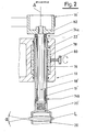
- Fig. 2 shows the upper part of the centering spindle arrangement.
- a clamp bearing 22 ' for the upper centering spindle 18', which is also referred to as a fixed spindle. It has a guide sleeve 19 ', which is supported radially and axially via support bearings 74a, 74b with respect to the inner centering spindle 18'.
- the clamp bearing 22 ' has a thin-walled sleeve 76 which surrounds the centering spindle 18' or its guide sleeve 19 'in the housing 10 and is in turn surrounded by a cavity 78 in which the adjusting screw 80 acting as a pressure piston corresponds to the respective requirement Clamping pressure on the guide sleeve 76 is adjustable.
- a lens L can be clamped with a clamping angle. This is the angle that the two tangents at the points of contact between the lens surfaces and the clamping bells 20, 20 'to each other. Due to the physical friction coefficient, the angle ⁇ must be greater than 2 x 8 °> 16 °.
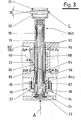
- the lower centering spindle arrangement according to FIG. 3 is used for clamping.
- the lower centering spindle 18 has also called a clamping spindle, also a guide sleeve 19, which is supported axially and radially via support bearings 84a, 84b with respect to the inner, actual centering spindle 18.
- a corrugated spring 82 is arranged between the lower support bearing 84a and a collar of a coupling piece 34, which permits a limited axial displacement of the guide sleeve and centering spindle relative to one another.
- the coupling piece 34 consists of two gear wheels 36, 37 with internal and external teeth, the gear wheel 36 being connected to the centering spindle 18 in a rotationally fixed manner.
- the gearwheel 37 is supported on the housing 10 via a radial bearing 35.
- the gear 36 is so wide that the gears 36, 37 do not come out of engagement even with the required axial displacement of the centering spindle.
- the gearwheel 37 is designed as a pulley on which the gear element 16 (ie a drive belt) engages.
- the tensioning device 24 has a plate 26 designed as a yoke, which has a hollow space with a membrane piston 32 in the center. By pressurizing the diaphragm piston 32 can be moved upward to raise the clamping spindle 18 together with the lens L resting on the clamping bell 20 to the upper clamping bell 20 '.
- the clamp bearing 22 for the clamping spindle 18 is additionally designed according to the invention as an air bearing.
- grooves 90 are provided on the periphery of the thin-walled guide sleeve 86, in particular at its two ends, which can be acted upon with pressure medium via control openings A i and B i .
- these grooves 90 are designed as axially parallel and partially annular channels, which in particular form four air cushion fields, thanks to which the centering spindle 18 or its outer sleeve 19 is axially displaceable in the clamp bearing 22 with extremely little friction, while at the same time ensuring an exact axial alignment of the centering spindle.
- the guide sleeve 19 of the clamping spindle 18 is guided in an air-supported manner, thereby reducing the friction for the axial clamping movement to a minimum and, at the same time, ensuring high alignment accuracy.
- the alignment forces required for aligning the lens L can be set sensitively by the membrane piston 32.
- the cavity 88 is put under high pressure by a pressure medium through the bore 98 and the thin-walled guide sleeve 8-6 deforms towards the center and clamps the clamping spindle precisely in alignment.
- the clamping force necessary for processing the lens L is transmitted to the centering spindle 18.
- the resulting slight axial movement of the clamping spindle 18 takes place in its own bearing 84a and 84b, the corrugated spring 82 being tensioned somewhat more.
Landscapes
- Engineering & Computer Science (AREA)
- Chemical & Material Sciences (AREA)
- Ceramic Engineering (AREA)
- Inorganic Chemistry (AREA)
- Mechanical Engineering (AREA)
- Grinding And Polishing Of Tertiary Curved Surfaces And Surfaces With Complex Shapes (AREA)
Abstract
Zum Zentrieren von optischen Linsen für die mechanische Halterung insbesondere beim Randschleifen und Facettieren schlägt die Erfindung eine Vorrichtung mit einem Gehäuse (10) vor, in dem ein motorischer Antrieb (M, R) über einen Drehmomentteiles (50), Antriebswellen (14, 14′) sowie Getriebeelemente (16, 16′) auf miteinander fluchtende Zentrierspindeln (18, 18′) wirkt. Diese sind in Führungslagern (22, 22′) an vorragenden Teilen des C-förmigen Gehäuses (10) angeordnet und als Luftlager ausgebildet. Dadurch kann der Einspannwinkel (α) an der Linse (L) im Bereich unterhalb 2 x 8°, vorzugsweise unterhalb 2 x 6° gehalten werden. Insbesondere die untere Zentrierspindel (18) ist im Luftlager (22) leichtgängig axialverstellbar, wozu achsparallele und/oder teilringförmige Nuten (90) an den Enden einer dünnwandigen Führungshülse (76) vorgesehen sind, zwischen denen sich bei Druckluftzufuhr Umfangs-Luftpolsterfelder aufbauen. Die axiale Zustellung der Spannspindel (18) erfolgt durch eine Spanneinrichtung (24) mit einer Jochplatte (26) und einem Membrankolben (32). 
Description
Die vorliegende Erfindung betrifft eine Vorrichtung zum Zentrieren von optischen Linsen für die mechanische Halterung insbesondere beim Randschleifen und Facettieren gemäß dem Oberbegriff von Anspruch 1.The present invention relates to a device for centering optical lenses for mechanical mounting, in particular for edge grinding and faceting, according to the preamble of
Gemäß der DE-PS 1 004 516 hat man hierzu die Linse mit hohem Druck zwischen zwei Glocken eingespannt, damit sich ihre Lage nicht mehr selbsttätig ändert. Zum Zentrieren der Linse wurden während des Spannvorganges die Spannglocken durch Ultraschall in Schwingungen versetzt, um die ruhende Reibung zwischen Glocke und Linse in eine niedrigere Gleitreibung umzuwandeln. Dieser Übergang erfolgte jedoch sprunghaft, wodurch häufig Beschädigungen der Linse mit unerwünschtem Materialabtrag auftraten.According to DE-PS 1 004 516, the lens has been clamped at high pressure between two bells so that its position no longer changes automatically. To center the lens, the clamping bells were vibrated by ultrasound during the clamping process in order to convert the static friction between the bell and the lens into a lower sliding friction. However, this transition took place by leaps and bounds, which often resulted in damage to the lens with undesired material removal.
Man hat ferner versucht, die Spannglocken beim Einspannen der Linse mit entgegengesetztem Drehsinn anzutreiben. Auch hierbei besteht ein hohes Beschädigungsrisiko, so daß sich Schleifspuren in Form von in die Linsenoberfläche eingeschnittenen Ringen kaum vermeiden lassen.Attempts have also been made to drive the clamping bells with the opposite direction of rotation when clamping the lens. There is also a high risk of damage here, so that grinding marks in the form of rings cut into the lens surface can hardly be avoided.
In der DE-AS 21 48 102 wurde vorgeschlagen, auf der höhenunveränderlichen Spannglocke einen piezokeramischen Rohrschwinger anzuordnen, der elektrisch über Schwellenwertschalter so gesteuert wird, daß die Spannglocke bei Erreichen eines vorgegebenen Druckes absinkt, wodurch der Schwingungsgenerator abgeschaltet wird. Der Piezoschwinger dient gleichzeitig zum Prüfen des Spanndruckes, dem die Schwingungsamplitude geregelt angepaßt wird. Bei dieser Anordnung sind Elektronik-Unsicherheiten nachteilig. Ferner hat der Schwinger eine nicht unbeachtliche Axialdruckempfindlichkeit. Durch die Druckbelastung beim Einspannen entsteht eine Vorspannung; die Abstützung des Schwingers ist daher problematisch.In DE-AS 21 48 102 it has been proposed to arrange a piezoceramic tube oscillator on the height-adjustable clamping bell, which is controlled electrically via threshold switches so that the clamping bell drops when a predetermined pressure is reached, as a result of which the vibration generator is switched off. The piezo oscillator is also used to check the clamping pressure to which the vibration amplitude is adjusted in a controlled manner. With this arrangement, electronics uncertainties are disadvantageous. Furthermore, the transducer has a not inconsiderable sensitivity to axial pressure. The pressure load during clamping creates a preload; the support of the transducer is therefore problematic.
Aus der DE-OS 31 39 873 ist eine Vorrichtung bekannt, bei der Unregelmäßigkeiten eines Zahnradantriebes ausgenutzt werden, um Relativbewegungen zwischen Linse und Spannglocken zu erzeugen. Als Ausgleichseinrichtung ist ein Waagebalken-Differential in einem Kegelrad-Getriebezug zwischen den beiden Teilen einer zweiteiligen Zentrierspindel und Antriebswelle vorgesehen. Für eine Druckplatte der oberen, axialbeweglichen Spindel ist ein hydraulischer Spannzylinder vorhanden. Infolge der hohen Reibung der Spannspindel in ihrer Gleitlagerung ist jedoch eine feine Regulierung des Einspanndruckes schwer zu realisieren, so daß auch diese Vorrichtung nur begrenzt anwendbar ist.From DE-OS 31 39 873 a device is known in which irregularities of a gear drive are exploited to generate relative movements between the lens and the clamping bell. As a compensation device, a balance beam differential is provided in a bevel gear train between the two parts of a two-part centering spindle and drive shaft. A hydraulic clamping cylinder is available for a pressure plate of the upper, axially movable spindle. Due to the high friction of the clamping spindle in its slide bearing, however, it is difficult to achieve fine regulation of the clamping pressure, so that this device can also be used only to a limited extent.
Es ist ein wichtiges Ziel der Erfindung, unter Überwindung der Nachteile des Standes der Technik das Zentrieren von Linsen insbesondere für die Schleifbearbeitung am Rand durch eine wesentlich verbesserte und leichtgängige Führung der Zentrierspindeln, durch erhöhte Haltekräfte sowie Genauigkeit der Einspannung zu verbessern, ohne den statischen Kraftaufwand zu steigern, so daß mechanische Beschädigungen der Linse sicher vermieden werden.It is an important object of the invention, while overcoming the disadvantages of the prior art, to center lenses, in particular for grinding on the edge, by means of a substantially improved and smooth guidance of the Centering spindles to improve by increased holding forces and accuracy of the clamping without increasing the static effort, so that mechanical damage to the lens can be avoided.
Die Aufgabe wird mit den Merkmalen des Anspruches 1 gelöst. Ausgestaltungen sind Gegenstand der Ansprüche 2 bis 7.The object is achieved with the features of
Gemäß der Erfindung ist jede Zentrierspindel in einer Hülse radial und axial gelagert, die wiederum über ein hydraulisches Spannelement im Maschinengestell festlegbar ist. Das Spannelement besteht aus einer Hülse, die von einem Hohlraum umgeben ist, wobei die Hülse bei Erhöhung des Druckes im Hohlraum verformt und gegen die Führungshülse der Zentrierspindel gepreßt wird. Hierdurch wird die Zentrierspindel in axialer Richtung festgelegt und gleichzeitig achsgenau ausgerichtet.According to the invention, each centering spindle is mounted radially and axially in a sleeve, which in turn can be fixed in the machine frame via a hydraulic clamping element. The clamping element consists of a sleeve which is surrounded by a cavity, the sleeve being deformed when the pressure in the cavity is increased and pressed against the guide sleeve of the centering spindle. As a result, the centering spindle is fixed in the axial direction and at the same time aligned with the axis.
Die bzw. jede Luftlagerung kann in der Hülse integriert sein, welche die zugeordnete Führungshülse der Zentrierspindel umschließt. Die obere Zentrierspindel ist zum Einrichten der Maschine axial verschiebbar und zentrisch festklemmbar. Eine als Druckkolben wirksame Stellschraube ermöglicht es, den Druck auf die Führungshülse dieser sogenannten Festspindel bedarfsgemäß einzustellen, ohne deren Achsausrichtung zu verändern.The or each air bearing can be integrated in the sleeve, which surrounds the associated guide sleeve of the centering spindle. The upper centering spindle can be moved axially and clamped in place to set up the machine. An adjusting screw which acts as a pressure piston makes it possible to adjust the pressure on the guide sleeve of this so-called fixed spindle as required without changing its axis orientation.
Die Zentrierspindel hat eine Außenhülse die in der Luftlagerhülse eng geführt und an den Enden axial und/oder radial abgestützt ist. Insbesondere die untere Zentrierspindel, die sogenannte Spannspindel, wird dadurch mit hoher zentrischer Genauigkeit und Leitgängigkeit axial geführt. Die fest im Maschinengehäuse sitzende Hülse für die Führungshülse der Spannspindel ist dabei genau fluchtend zur Hülse für die Führungshülse der Festspindel angeordnet.The centering spindle has an outer sleeve which is guided closely in the air bearing sleeve and is axially and / or radially supported at the ends. In particular, the lower centering spindle, the so-called clamping spindle, becomes more centric Axial accuracy and conductivity. The sleeve for the guide sleeve of the clamping spindle, which is firmly seated in the machine housing, is precisely aligned with the sleeve for the guide sleeve of the fixed spindle.
Eine sehr günstige Weiterbildung der Luftlagerung besteht darin, daß zwischen dem Gehäuse und zumindest der unteren Führungshülse der Zentrierspindel Nuten vorhanden sind, die über Steueröffnungen mit Druckmittel beaufschlagbar sind. Die Nuten können achsparallele und/oder teilringförmige Kanäle bilden. Bevorzugt ist die Innenwand der Führungshülsenbohrung mit Kanälen und Taschen so gestaltet, daß in der oberen und unteren Hälfte je vier Luftpolsterfelder entstehen, welche die Spannspindel bei Druckluftzufuhr mit äußerst geringer Reibung positionsstabil lagern. Die Luftlagerung und die damit verbundene Leichtgängigkeit der Spannspindel und der Membrankolben ermöglichen es für das Ausrichten der Linse die Ausrichtkräfte sehr klein zu halten und diese feinfühlig einzustellen, wodurch eine Beschädigung der Linsenoberfläche während ihrer Ausrichtbewegung vermieden wird. Hat die Linse ihre genaue Ausrichtposition erreicht, wird der die Spannhülse umgebende Hohlraum mit hohem Druck beaufschlagt, so daß die Spannspindel in ihrer Lage achsgenau und zentrisch festgeklemmt wird. Die zugeführte Druckluft ist auch während des Bearbeitungsvorganges sehr förderlich, um das Eindringen von Kühl- und Schleifmitteln bzw. Materialabrieb zwischen der Führungshülse und der Spannspindel zu vermeiden.A very favorable development of the air bearing is that there are grooves between the housing and at least the lower guide sleeve of the centering spindle, which can be acted upon with pressure medium via control openings. The grooves can form axially parallel and / or partially annular channels. The inner wall of the guide sleeve bore is preferably designed with channels and pockets in such a way that four air cushion fields are formed in the upper and lower half, which support the clamping spindle in a positionally stable manner with compressed air supply with extremely low friction. The air bearing and the associated ease of movement of the clamping spindle and the diaphragm piston make it possible to keep the alignment forces very small for the alignment of the lens and to adjust them sensitively, thereby avoiding damage to the lens surface during its alignment movement. When the lens has reached its precise alignment position, the cavity surrounding the clamping sleeve is subjected to high pressure, so that the clamping spindle is clamped in its position in an exact and centric position. The compressed air supplied is also very beneficial during the machining process in order to prevent the penetration of coolants and abrasives or material abrasion between the guide sleeve and the clamping spindle.
Weitere Merkmale, Einzelheiten und Vorteile der Erfindung ergeben sich aus dem Wortlaut der Ansprüche sowie aus der folgenden Beschreibung eines Ausführungsbeispiels anhand der Zeichnung. Darin zeigen:
- Fig. 1 eine Axialschnitt-Gesamtansicht einer Zentriervorrichtung,
- Fig. 2 eine vergrößerte Axialschnitt-Ansicht einer oberen Zentrierspindel-Führung,
- Fig. 3 eine vergrößerte Axialschnitt-Ansicht einer unteren Zentrierspindel-Führung mit Spanneinrichtung,
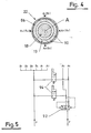
- Fig. 4 eine weiter vergrößerte Querschnittsansicht entsprechend der Ebene Ai-Ai in Fig. 3 und
- Fig. 5 eine schematische Darstellung der Druckmittel-Steuerung für die Anordnung gemäß Fig. 3 und 4.
- 1 is an overall axial section view of a centering device,
- 2 is an enlarged axial sectional view of an upper centering spindle guide,
- 3 is an enlarged axial sectional view of a lower centering spindle guide with a clamping device,
- Fig. 4 is a further enlarged cross-sectional view corresponding to the plane A i -A i in Fig. 3 and
- 5 shows a schematic illustration of the pressure medium control for the arrangement according to FIGS. 3 and 4.
Die Gesamtansicht von Fig. 1 veranschaulicht eine Vorrichtung mit einem Gehäuse 10, das eine Lagerung 12 für fluchtende Antriebswellen 14, 14′ aufweist, welche über Getriebeelemente 16, 16′ auf unter sich ebenfalls fluchtende Zentrierspindeln 18, 18′ wirken. Diese tragen an ihren freien Enden Spannglocken 20, 20′, zwischen denen eine Linse L zur Bearbeitung ausrichtbar und einspannbar ist. Zum Antrieb dient ein Motor M, der über einen Riemenantrieb R und einen Drehmomentteiler 50 auf die beiden Antriebswellen 14, 14′ wirkt.The overall view of Fig. 1 illustrates a device with a
Im unteren Teil des C-förmig gestalteten Gehäuses 10 befindet sich eine Kammer 44, in der eine Spanneinrichtung 24 untergebracht ist. Diese ermöglicht es, die untere Zentrierspindel 18 gegenüber der oberen Zentrierspindel 18′ in Achsrichtung A zu verschieben, um die Linse L festzuspannen.In the lower part of the C-
Fig. 2 zeigt den oberen Teil der Zentrierspindel-Anordnung. In einem vorragenden Teil des Gehäuses 10 befindet sich ein Klemmlager 22′ für die oberen Zentrierspindel 18′, die auch als Festspindel bezeichnet wird. Sie hat eine Führungshülse 19′, welche über Stützlager 74a, 74b gegenüber der inneren Zentrierspindel 18′ radial und axil abgestützt ist.Fig. 2 shows the upper part of the centering spindle arrangement. In a projecting part of the
Das Klemmlager 22′ weist eine dünnwandige Hülse 76 auf, welche die Zentrierspindel 18′ bzw. ihrer Führungshülse 19′ im Gehäuse 10 anliegend umschließt ünd ihrerseits von einem Hohlraum 78 umgeben ist, in welchem mittels einer als Druckkolben wirkenden Stellschraube 80 der dem jeweiligem Bedarf entsprechende Klemmdruck auf die Führungshülse 76 einstellbar ist.The clamp bearing 22 'has a thin-
Zwischen der oberen Spannglocke 20′ und der unteren Spannglocke 20 ist eine Linse L mit einem Einspannwinkel einspannbar. Das ist derjenige Winkel, den die beiden Tangenten an den Berührungsstellen zwischen den Linsenoberflächen und den Spannglocken 20, 20′ zueinander einnehmen. Durch den Haftreibungskoeffizienten physikalisch bedingt, muß der Winkel α größer als 2 x 8° > 16° sein.Between the upper clamping bell 20 'and the
Zum Einspannen dient die untere Zentrierspindel-Anordnung gemäß Fig. 3. Hierbei hat die untere Zentrierspindel 18, auch Spannspindel genannt, ebenfalls eine Führungshülse 19, die über Stützlager 84a, 84b gegenüber der inneren, eigentlichen Zentrierspindel 18 axial und radial abgestützt ist. Zwischen dem unteren Stützlager 84a und einem Bund eines Kupplungs-stücks 34 ist eine Wellfeder 82 angeordnet, die eine begrenzte axiale Verschiebung von Führungshülse und Zentrierspindel zueinander gestattet. Das Kupplungsstück 34 besteht aus zwei Zahnrädern 36, 37 mit Innen- und Außenverzahnung, wobei das Zahnrad 36 mit der Zentrierspindel 18 drehfest verbunden ist. Das Zahnrad 37 ist über ein Radiallager 35 am Gehäuse 10 abgestützt. Das Zahnrad 36 ist so breit, daß auch bei der erforderlichen axialen Verschiebung der Zentrierspindel die Zahnräder 36, 37 nicht außer Eingriff kommen. Am Umfang ist das Zahnrad 37 als Riemenscheibe ausgebildet, an welcher das Getriebeelement 16 (also ein Treibriemen) angreift.The lower centering spindle arrangement according to FIG. 3 is used for clamping. Here, the
Die Spanneinrichtung 24 weist eine als Joch ausgebildete Platte 26 auf, die zentrisch einen Hohlraum mit einem Membrankolben 32 hat. Durch Druckmittelbeaufschlagung kann der Membrankolben 32 aufwärts bewegt werden, um die Spannspindel 18 samt der auf der Spannglocke 20 ruhenden Linse L zu der oberen Spannglocke 20′ hin anzuheben.The
Um diese Zustellbewegung möglichst leichtgängig durchführen zu können, ist das Klemmlager 22 für die Spannspindel 18 erfindungsgemäß zusätzlich als Luftlager ausgebildet. Am Umfang der dünnwandigen Führungshülse 86, insbesondere an deren beiden Enden, sind hierzu Nuten 90 vorgesehen, welche ber Steueröffnungen Ai und Bi mit Druckmittel beaufschlagbar sind. In Verbindung mit Fig. 4 ist ersichtlich, daß diese Nuten 90 als achsparallele und teilringförmige Kanäle gestaltet sind, welche insbesondere je vier Luftpolsterfelder bilden, dank welcher die Zentrierspindel 18 bzw. deren Außenhülse 19 im Klemmlager 22 mit überaus geringer Reibung axialverschieblich ist, wobei gleichzeitig eine exakte axiale Ausrichtung der Zentrierspindel gewährleistet ist.In order to be able to carry out this feed movement as smoothly as possible, the clamp bearing 22 for the clamping
Durch die Druckbeaufschlagung wird die Führungshülse 19 der Spannspindel 18 luftgelagert geführt und dadurch die Reibung für die axiale Spannbewegung auf ein Minimum reduziert und gleichzeitig eine hohe Achsfluchtgenauigkeit gewährleistet. Durch den Membrankolben 32 können die zum Ausrichten der Linse L benötigten Ausrichtkräfte feinfühlig eingestellt werden. Nach dem Ausrichten wird durch die Bohrung 98 der Hohlraum 88 durch ein Druckmedium unter hohen Druck gestellt und die dünnwandige Führungshülse 8-6 deformiert sich zum Zentrum hin und klemmt die Spannspindel genau fluchtend fest. Über das Joch 26 und das Axiallager 33 wird die zur Bearbeitung der Linse L notwendige Spannkraft auf die Zentrierspindel 18 übertragen. Die hierdurch entstehende geringe Axialbewegung der Spannspindel 18 geschieht in der eigenen Lagerung 84a und 84b wobei die Wellfeder 82 etwas stärker gespannt wird.Due to the pressurization, the
Sämtliche aus den Ansprüchen, der Beschreibung und der Zeichnung hervorgehenden Merkmale und Vorteile, einschließlich konstruktiver Einzelheiten, räumlicher Anordnungen und Verfahrensschritten, können sowohl für sich als auch in den verschiedensten Kombinationen erfindungswesentlich sein.All of the features and advantages arising from the claims, the description and the drawing, including constructive details, spatial arrangements and method steps, can be essential to the invention both individually and in the most varied of combinations.
Claims (7)
Applications Claiming Priority (2)
| Application Number | Priority Date | Filing Date | Title |
|---|---|---|---|
| DE3744115 | 1987-12-24 | ||
| DE3744115A DE3744115C2 (en) | 1987-12-24 | 1987-12-24 | Machine for centering edge grinding and faceting optical lenses for their mechanical mounting |
Publications (3)
| Publication Number | Publication Date |
|---|---|
| EP0322579A2 true EP0322579A2 (en) | 1989-07-05 |
| EP0322579A3 EP0322579A3 (en) | 1990-09-05 |
| EP0322579B1 EP0322579B1 (en) | 1993-02-03 |
Family
ID=6343615
Family Applications (1)
| Application Number | Title | Priority Date | Filing Date |
|---|---|---|---|
| EP88119934A Expired - Lifetime EP0322579B1 (en) | 1987-12-24 | 1988-11-30 | Device for centering optical lenses for mechanical clamping, especially during bevelling and facetting |
Country Status (4)
| Country | Link |
|---|---|
| US (1) | US4951421A (en) |
| EP (1) | EP0322579B1 (en) |
| DE (1) | DE3744115C2 (en) |
| ES (1) | ES2037805T3 (en) |
Families Citing this family (5)
| Publication number | Priority date | Publication date | Assignee | Title |
|---|---|---|---|---|
| US6257968B1 (en) | 1998-12-16 | 2001-07-10 | National Optronics, Incorporated | Quick-release lens clamp pad assembly for use in eyeglass lens processing |
| US6243960B1 (en) | 1999-03-16 | 2001-06-12 | National Optronics, Incorporated | Tracer, clamp and object engager for holding and tracing a lens mount of an eyeglass frame, a lens, and/or a lens pattern, to reliably detect a shape thereof even when the shape includes high wrap |
| USD435053S (en) * | 1999-03-16 | 2000-12-12 | National Optronics, Incorporated | Eyeglass frame tracer |
| US6249991B1 (en) | 1999-03-17 | 2001-06-26 | National Optronics, Incorporated | Control system for eyeglass tracer |
| DE10008710C2 (en) | 2000-02-24 | 2002-01-10 | Loh Optikmaschinen Ag | Device for centering clamping of optical lenses for their edge processing |
Family Cites Families (15)
| Publication number | Priority date | Publication date | Assignee | Title |
|---|---|---|---|---|
| US2508009A (en) * | 1946-09-11 | 1950-05-16 | Simonds Machine Co Inc | Edging machine |
| NL152774A (en) * | 1950-01-24 | |||
| BE498786A (en) * | 1950-01-24 | |||
| DE1004516B (en) * | 1956-03-02 | 1957-03-14 | Voigtlaender Ag | Method and machine for centering optical lenses |
| US3143382A (en) * | 1961-06-06 | 1964-08-04 | Commissariat Energie Atomique | Aerodynamic bearing |
| US3599377A (en) * | 1968-07-22 | 1971-08-17 | Bausch & Lomb | Lens alignment using gas bearings |
| GB1310135A (en) * | 1970-07-22 | 1973-03-14 | Raphael O P | Method of and apparatus for filling spectacle lenses |
| DE2148102C3 (en) * | 1971-09-27 | 1979-07-05 | Ernst Leitz Wetzlar Gmbh, 6300 Lahn- Wetzlar | Method for centering lenses |
| GB1332414A (en) * | 1971-12-02 | 1973-10-03 | Produmatic Sa | Machine tools |
| DK338978A (en) * | 1977-08-02 | 1979-02-03 | Automated Optics | CONTACT LENS AND METHOD AND MACHINE FOR MANUFACTURE OF SUCH LENSES |
| DE2756407A1 (en) * | 1977-12-17 | 1979-06-21 | Prontor Werk Gauthier Gmbh | Lens grinding machine securing spindle bearing system - uses stack of bushes each end, compressed around spindle by adjusting screws |
| DE3139873C2 (en) * | 1981-10-07 | 1983-11-10 | Prontor-Werk Alfred Gauthier Gmbh, 7547 Wildbad | Machine for edge grinding and faceting of optical lenses |
| FR2553323B1 (en) * | 1983-10-18 | 1986-07-25 | Essilor Int | METHOD AND MACHINE FOR BEVELING OR SLOTTING AN OPHTHALMIC LENS |
| DE3526539C1 (en) * | 1985-07-24 | 1986-11-13 | Erwin 7611 Nordrach Junker | Process for precision quick clamping of rotationally symmetrical workpieces and precision quick clamping device for carrying out the process |
| DE8702561U1 (en) * | 1987-02-19 | 1987-06-04 | Wernicke & Co GmbH, 4000 Düsseldorf | Lens holder for spectacle lens edge grinding machines |
-
1987
- 1987-12-24 DE DE3744115A patent/DE3744115C2/en not_active Expired - Fee Related
-
1988
- 1988-11-30 ES ES198888119934T patent/ES2037805T3/en not_active Expired - Lifetime
- 1988-11-30 EP EP88119934A patent/EP0322579B1/en not_active Expired - Lifetime
- 1988-12-23 US US07/289,920 patent/US4951421A/en not_active Expired - Fee Related
Also Published As
| Publication number | Publication date |
|---|---|
| ES2037805T3 (en) | 1993-07-01 |
| EP0322579B1 (en) | 1993-02-03 |
| DE3744115C2 (en) | 1994-03-31 |
| US4951421A (en) | 1990-08-28 |
| DE3744115A1 (en) | 1989-07-06 |
| EP0322579A3 (en) | 1990-09-05 |
Similar Documents
| Publication | Publication Date | Title |
|---|---|---|
| DE19825698B4 (en) | belt sander | |
| DE3407615C2 (en) | ||
| DE4311940C2 (en) | Universal testing machine | |
| EP1044760B1 (en) | Clamping device | |
| DE102012009110B4 (en) | honing tool | |
| EP1742762B1 (en) | Device for the production of microstructures | |
| WO2017036876A2 (en) | Machine tool having a fine machining spindle | |
| DE69107676T2 (en) | Boring head. | |
| EP0322580B1 (en) | Device for centering optical lenses for mechanical clamping, especially during bevelling and facetting | |
| EP2934816B1 (en) | Spindle of a grinding machine tool | |
| EP0322579B1 (en) | Device for centering optical lenses for mechanical clamping, especially during bevelling and facetting | |
| EP0146149B1 (en) | Auxiliary device for accurate of a cylindrical surface and a curved shoulder on a work piece | |
| DE19531506C1 (en) | Grinding machine, in particular cylindrical grinding machine | |
| EP0323572B1 (en) | Device for centering optical lenses for mechanical clamping, espcially during bevelling and facetting | |
| DE69400964T2 (en) | TORIC LENS HOLDING DEVICE | |
| DE3239720T1 (en) | INTERNAL GRINDING MACHINE | |
| EP3251788B1 (en) | Device for supporting a workpiece to be machined | |
| EP0322578A2 (en) | Device for centering optical lenses for mechanical clamping, especially during bevelling and facetting | |
| CH671177A5 (en) | ||
| DE2334667B2 (en) | Honing tool | |
| DE3617790A1 (en) | Ultrasonic machine tool | |
| DE20219615U1 (en) | Machine tool for grinding optical components, e.g. lenses, includes piston with tappets supporting grinding films or pellets at one end | |
| DE906782C (en) | Device for the drive of vibrating systems with several masses for the fine machining of surfaces | |
| DE1176880B (en) | Pneumatic teaching on precision grinding machines | |
| DE2407261C3 (en) | Device for grinding the flat face on an otherwise hollow-cylindrical workpiece |
Legal Events
| Date | Code | Title | Description |
|---|---|---|---|
| PUAI | Public reference made under article 153(3) epc to a published international application that has entered the european phase |
Free format text: ORIGINAL CODE: 0009012 |
|
| AK | Designated contracting states |
Kind code of ref document: A2 Designated state(s): CH ES FR GB IT LI |
|
| PUAL | Search report despatched |
Free format text: ORIGINAL CODE: 0009013 |
|
| AK | Designated contracting states |
Kind code of ref document: A3 Designated state(s): CH ES FR GB IT LI |
|
| 17P | Request for examination filed |
Effective date: 19901002 |
|
| 17Q | First examination report despatched |
Effective date: 19920413 |
|
| GRAA | (expected) grant |
Free format text: ORIGINAL CODE: 0009210 |
|
| AK | Designated contracting states |
Kind code of ref document: B1 Designated state(s): CH ES FR GB IT LI |
|
| ITF | It: translation for a ep patent filed | ||
| GBT | Gb: translation of ep patent filed (gb section 77(6)(a)/1977) |
Effective date: 19930225 |
|
| ET | Fr: translation filed | ||
| REG | Reference to a national code |
Ref country code: ES Ref legal event code: FG2A Ref document number: 2037805 Country of ref document: ES Kind code of ref document: T3 |
|
| PLBE | No opposition filed within time limit |
Free format text: ORIGINAL CODE: 0009261 |
|
| STAA | Information on the status of an ep patent application or granted ep patent |
Free format text: STATUS: NO OPPOSITION FILED WITHIN TIME LIMIT |
|
| 26N | No opposition filed | ||
| PGFP | Annual fee paid to national office [announced via postgrant information from national office to epo] |
Ref country code: GB Payment date: 19941122 Year of fee payment: 7 |
|
| PGFP | Annual fee paid to national office [announced via postgrant information from national office to epo] |
Ref country code: ES Payment date: 19941130 Year of fee payment: 7 |
|
| PGFP | Annual fee paid to national office [announced via postgrant information from national office to epo] |
Ref country code: CH Payment date: 19951013 Year of fee payment: 8 |
|
| PGFP | Annual fee paid to national office [announced via postgrant information from national office to epo] |
Ref country code: FR Payment date: 19951020 Year of fee payment: 8 |
|
| PG25 | Lapsed in a contracting state [announced via postgrant information from national office to epo] |
Ref country code: GB Effective date: 19951130 |
|
| PG25 | Lapsed in a contracting state [announced via postgrant information from national office to epo] |
Ref country code: ES Free format text: LAPSE BECAUSE OF THE APPLICANT RENOUNCES Effective date: 19951201 |
|
| GBPC | Gb: european patent ceased through non-payment of renewal fee |
Effective date: 19951130 |
|
| PG25 | Lapsed in a contracting state [announced via postgrant information from national office to epo] |
Ref country code: LI Effective date: 19961130 Ref country code: CH Effective date: 19961130 |
|
| REG | Reference to a national code |
Ref country code: CH Ref legal event code: PL |
|
| PG25 | Lapsed in a contracting state [announced via postgrant information from national office to epo] |
Ref country code: FR Effective date: 19970731 |
|
| REG | Reference to a national code |
Ref country code: FR Ref legal event code: ST |
|
| REG | Reference to a national code |
Ref country code: ES Ref legal event code: FD2A Effective date: 20010402 |
|
| PG25 | Lapsed in a contracting state [announced via postgrant information from national office to epo] |
Ref country code: IT Free format text: LAPSE BECAUSE OF NON-PAYMENT OF DUE FEES;WARNING: LAPSES OF ITALIAN PATENTS WITH EFFECTIVE DATE BEFORE 2007 MAY HAVE OCCURRED AT ANY TIME BEFORE 2007. THE CORRECT EFFECTIVE DATE MAY BE DIFFERENT FROM THE ONE RECORDED. Effective date: 20051130 |