EP0322579A2 - Dispositif de centrage de lentilles optiques pour le montage mécanique, en particulier lors du meulage des bords et de facettes - Google Patents
Dispositif de centrage de lentilles optiques pour le montage mécanique, en particulier lors du meulage des bords et de facettes Download PDFInfo
- Publication number
- EP0322579A2 EP0322579A2 EP88119934A EP88119934A EP0322579A2 EP 0322579 A2 EP0322579 A2 EP 0322579A2 EP 88119934 A EP88119934 A EP 88119934A EP 88119934 A EP88119934 A EP 88119934A EP 0322579 A2 EP0322579 A2 EP 0322579A2
- Authority
- EP
- European Patent Office
- Prior art keywords
- clamping
- centering
- guide sleeve
- spindle
- axially
- Prior art date
- Legal status (The legal status is an assumption and is not a legal conclusion. Google has not performed a legal analysis and makes no representation as to the accuracy of the status listed.)
- Granted
Links
Images

Classifications
-
- B—PERFORMING OPERATIONS; TRANSPORTING
- B24—GRINDING; POLISHING
- B24B—MACHINES, DEVICES, OR PROCESSES FOR GRINDING OR POLISHING; DRESSING OR CONDITIONING OF ABRADING SURFACES; FEEDING OF GRINDING, POLISHING, OR LAPPING AGENTS
- B24B9/00—Machines or devices designed for grinding edges or bevels on work or for removing burrs; Accessories therefor
- B24B9/02—Machines or devices designed for grinding edges or bevels on work or for removing burrs; Accessories therefor characterised by a special design with respect to properties of materials specific to articles to be ground
- B24B9/06—Machines or devices designed for grinding edges or bevels on work or for removing burrs; Accessories therefor characterised by a special design with respect to properties of materials specific to articles to be ground of non-metallic inorganic material, e.g. stone, ceramics, porcelain
- B24B9/08—Machines or devices designed for grinding edges or bevels on work or for removing burrs; Accessories therefor characterised by a special design with respect to properties of materials specific to articles to be ground of non-metallic inorganic material, e.g. stone, ceramics, porcelain of glass
- B24B9/14—Machines or devices designed for grinding edges or bevels on work or for removing burrs; Accessories therefor characterised by a special design with respect to properties of materials specific to articles to be ground of non-metallic inorganic material, e.g. stone, ceramics, porcelain of glass of optical work, e.g. lenses, prisms
- B24B9/146—Accessories, e.g. lens mounting devices
-
- Y—GENERAL TAGGING OF NEW TECHNOLOGICAL DEVELOPMENTS; GENERAL TAGGING OF CROSS-SECTIONAL TECHNOLOGIES SPANNING OVER SEVERAL SECTIONS OF THE IPC; TECHNICAL SUBJECTS COVERED BY FORMER USPC CROSS-REFERENCE ART COLLECTIONS [XRACs] AND DIGESTS
- Y10—TECHNICAL SUBJECTS COVERED BY FORMER USPC
- Y10T—TECHNICAL SUBJECTS COVERED BY FORMER US CLASSIFICATION
- Y10T82/00—Turning
- Y10T82/25—Lathe
- Y10T82/2552—Headstock
- Y10T82/2562—Spindle and bearings
-
- Y—GENERAL TAGGING OF NEW TECHNOLOGICAL DEVELOPMENTS; GENERAL TAGGING OF CROSS-SECTIONAL TECHNOLOGIES SPANNING OVER SEVERAL SECTIONS OF THE IPC; TECHNICAL SUBJECTS COVERED BY FORMER USPC CROSS-REFERENCE ART COLLECTIONS [XRACs] AND DIGESTS
- Y10—TECHNICAL SUBJECTS COVERED BY FORMER USPC
- Y10T—TECHNICAL SUBJECTS COVERED BY FORMER US CLASSIFICATION
- Y10T82/00—Turning
- Y10T82/25—Lathe
- Y10T82/2568—Center
- Y10T82/2571—Alignment adjuster
-
- Y—GENERAL TAGGING OF NEW TECHNOLOGICAL DEVELOPMENTS; GENERAL TAGGING OF CROSS-SECTIONAL TECHNOLOGIES SPANNING OVER SEVERAL SECTIONS OF THE IPC; TECHNICAL SUBJECTS COVERED BY FORMER USPC CROSS-REFERENCE ART COLLECTIONS [XRACs] AND DIGESTS
- Y10—TECHNICAL SUBJECTS COVERED BY FORMER USPC
- Y10T—TECHNICAL SUBJECTS COVERED BY FORMER US CLASSIFICATION
- Y10T82/00—Turning
- Y10T82/27—Centerer
Definitions
- the present invention relates to a device for centering optical lenses for mechanical mounting, in particular for edge grinding and faceting, according to the preamble of claim 1.
- the lens has been clamped at high pressure between two bells so that its position no longer changes automatically.
- the clamping bells were vibrated by ultrasound during the clamping process in order to convert the static friction between the bell and the lens into a lower sliding friction.
- this transition took place by leaps and bounds, which often resulted in damage to the lens with undesired material removal.
- DE-AS 21 48 102 it has been proposed to arrange a piezoceramic tube oscillator on the height-adjustable clamping bell, which is controlled electrically via threshold switches so that the clamping bell drops when a predetermined pressure is reached, as a result of which the vibration generator is switched off.
- the piezo oscillator is also used to check the clamping pressure to which the vibration amplitude is adjusted in a controlled manner.
- electronics uncertainties are disadvantageous.
- the transducer has a not inconsiderable sensitivity to axial pressure. The pressure load during clamping creates a preload; the support of the transducer is therefore problematic.
- a device is known in which irregularities of a gear drive are exploited to generate relative movements between the lens and the clamping bell.
- a balance beam differential is provided in a bevel gear train between the two parts of a two-part centering spindle and drive shaft.
- a hydraulic clamping cylinder is available for a pressure plate of the upper, axially movable spindle. Due to the high friction of the clamping spindle in its slide bearing, however, it is difficult to achieve fine regulation of the clamping pressure, so that this device can also be used only to a limited extent.
- each centering spindle is mounted radially and axially in a sleeve, which in turn can be fixed in the machine frame via a hydraulic clamping element.
- the clamping element consists of a sleeve which is surrounded by a cavity, the sleeve being deformed when the pressure in the cavity is increased and pressed against the guide sleeve of the centering spindle.
- the or each air bearing can be integrated in the sleeve, which surrounds the associated guide sleeve of the centering spindle.
- the upper centering spindle can be moved axially and clamped in place to set up the machine.
- An adjusting screw which acts as a pressure piston makes it possible to adjust the pressure on the guide sleeve of this so-called fixed spindle as required without changing its axis orientation.
- the centering spindle has an outer sleeve which is guided closely in the air bearing sleeve and is axially and / or radially supported at the ends.
- the lower centering spindle the so-called clamping spindle
- the sleeve for the guide sleeve of the clamping spindle which is firmly seated in the machine housing, is precisely aligned with the sleeve for the guide sleeve of the fixed spindle.
- a very favorable development of the air bearing is that there are grooves between the housing and at least the lower guide sleeve of the centering spindle, which can be acted upon with pressure medium via control openings.
- the grooves can form axially parallel and / or partially annular channels.
- the inner wall of the guide sleeve bore is preferably designed with channels and pockets in such a way that four air cushion fields are formed in the upper and lower half, which support the clamping spindle in a positionally stable manner with compressed air supply with extremely low friction.
- the cavity surrounding the clamping sleeve is subjected to high pressure, so that the clamping spindle is clamped in its position in an exact and centric position.
- the compressed air supplied is also very beneficial during the machining process in order to prevent the penetration of coolants and abrasives or material abrasion between the guide sleeve and the clamping spindle.
- FIG. 1 illustrates a device with a housing 10 having a bearing 12 for aligned drive shafts 14, 14 ', which act on gear elements 16, 16' on also aligned centering spindles 18, 18 '. These wear at their free ends clamping bells 20, 20 ', between which a lens L can be aligned and clamped for processing.
- a motor M which acts via a belt drive R and a torque divider 50 on the two drive shafts 14, 14 '.
- a chamber 44 in which a tensioning device 24 is accommodated. This makes it possible to move the lower centering spindle 18 'relative to the upper centering spindle 18' in the axial direction A in order to clamp the lens L.
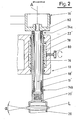
- Fig. 2 shows the upper part of the centering spindle arrangement.
- a clamp bearing 22 ' for the upper centering spindle 18', which is also referred to as a fixed spindle. It has a guide sleeve 19 ', which is supported radially and axially via support bearings 74a, 74b with respect to the inner centering spindle 18'.
- the clamp bearing 22 ' has a thin-walled sleeve 76 which surrounds the centering spindle 18' or its guide sleeve 19 'in the housing 10 and is in turn surrounded by a cavity 78 in which the adjusting screw 80 acting as a pressure piston corresponds to the respective requirement Clamping pressure on the guide sleeve 76 is adjustable.
- a lens L can be clamped with a clamping angle. This is the angle that the two tangents at the points of contact between the lens surfaces and the clamping bells 20, 20 'to each other. Due to the physical friction coefficient, the angle ⁇ must be greater than 2 x 8 °> 16 °.
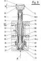
- the lower centering spindle arrangement according to FIG. 3 is used for clamping.
- the lower centering spindle 18 has also called a clamping spindle, also a guide sleeve 19, which is supported axially and radially via support bearings 84a, 84b with respect to the inner, actual centering spindle 18.
- a corrugated spring 82 is arranged between the lower support bearing 84a and a collar of a coupling piece 34, which permits a limited axial displacement of the guide sleeve and centering spindle relative to one another.
- the coupling piece 34 consists of two gear wheels 36, 37 with internal and external teeth, the gear wheel 36 being connected to the centering spindle 18 in a rotationally fixed manner.
- the gearwheel 37 is supported on the housing 10 via a radial bearing 35.
- the gear 36 is so wide that the gears 36, 37 do not come out of engagement even with the required axial displacement of the centering spindle.
- the gearwheel 37 is designed as a pulley on which the gear element 16 (ie a drive belt) engages.
- the tensioning device 24 has a plate 26 designed as a yoke, which has a hollow space with a membrane piston 32 in the center. By pressurizing the diaphragm piston 32 can be moved upward to raise the clamping spindle 18 together with the lens L resting on the clamping bell 20 to the upper clamping bell 20 '.
- the clamp bearing 22 for the clamping spindle 18 is additionally designed according to the invention as an air bearing.
- grooves 90 are provided on the periphery of the thin-walled guide sleeve 86, in particular at its two ends, which can be acted upon with pressure medium via control openings A i and B i .
- these grooves 90 are designed as axially parallel and partially annular channels, which in particular form four air cushion fields, thanks to which the centering spindle 18 or its outer sleeve 19 is axially displaceable in the clamp bearing 22 with extremely little friction, while at the same time ensuring an exact axial alignment of the centering spindle.
- the guide sleeve 19 of the clamping spindle 18 is guided in an air-supported manner, thereby reducing the friction for the axial clamping movement to a minimum and, at the same time, ensuring high alignment accuracy.
- the alignment forces required for aligning the lens L can be set sensitively by the membrane piston 32.
- the cavity 88 is put under high pressure by a pressure medium through the bore 98 and the thin-walled guide sleeve 8-6 deforms towards the center and clamps the clamping spindle precisely in alignment.
- the clamping force necessary for processing the lens L is transmitted to the centering spindle 18.
- the resulting slight axial movement of the clamping spindle 18 takes place in its own bearing 84a and 84b, the corrugated spring 82 being tensioned somewhat more.
Landscapes
- Engineering & Computer Science (AREA)
- Chemical & Material Sciences (AREA)
- Ceramic Engineering (AREA)
- Inorganic Chemistry (AREA)
- Mechanical Engineering (AREA)
- Grinding And Polishing Of Tertiary Curved Surfaces And Surfaces With Complex Shapes (AREA)
Applications Claiming Priority (2)
| Application Number | Priority Date | Filing Date | Title |
|---|---|---|---|
| DE3744115 | 1987-12-24 | ||
| DE3744115A DE3744115C2 (de) | 1987-12-24 | 1987-12-24 | Maschine zum zentrierenden Randschleifen und Facettieren von optischen Linsen für ihre mechanische Halterung |
Publications (3)
| Publication Number | Publication Date |
|---|---|
| EP0322579A2 true EP0322579A2 (fr) | 1989-07-05 |
| EP0322579A3 EP0322579A3 (en) | 1990-09-05 |
| EP0322579B1 EP0322579B1 (fr) | 1993-02-03 |
Family
ID=6343615
Family Applications (1)
| Application Number | Title | Priority Date | Filing Date |
|---|---|---|---|
| EP88119934A Expired - Lifetime EP0322579B1 (fr) | 1987-12-24 | 1988-11-30 | Dispositif de centrage de lentilles optiques pour le montage mécanique, en particulier lors du meulage des bords et de facettes |
Country Status (4)
| Country | Link |
|---|---|
| US (1) | US4951421A (fr) |
| EP (1) | EP0322579B1 (fr) |
| DE (1) | DE3744115C2 (fr) |
| ES (1) | ES2037805T3 (fr) |
Families Citing this family (5)
| Publication number | Priority date | Publication date | Assignee | Title |
|---|---|---|---|---|
| US6257968B1 (en) | 1998-12-16 | 2001-07-10 | National Optronics, Incorporated | Quick-release lens clamp pad assembly for use in eyeglass lens processing |
| US6243960B1 (en) | 1999-03-16 | 2001-06-12 | National Optronics, Incorporated | Tracer, clamp and object engager for holding and tracing a lens mount of an eyeglass frame, a lens, and/or a lens pattern, to reliably detect a shape thereof even when the shape includes high wrap |
| USD435053S (en) * | 1999-03-16 | 2000-12-12 | National Optronics, Incorporated | Eyeglass frame tracer |
| US6249991B1 (en) | 1999-03-17 | 2001-06-26 | National Optronics, Incorporated | Control system for eyeglass tracer |
| DE10008710C2 (de) | 2000-02-24 | 2002-01-10 | Loh Optikmaschinen Ag | Vorrichtung zum zentrierenden Spannen von optischen Linsen für deren Randbearbeitung |
Family Cites Families (15)
| Publication number | Priority date | Publication date | Assignee | Title |
|---|---|---|---|---|
| US2508009A (en) * | 1946-09-11 | 1950-05-16 | Simonds Machine Co Inc | Edging machine |
| NL152774A (fr) * | 1950-01-24 | |||
| BE498786A (fr) * | 1950-01-24 | |||
| DE1004516B (de) * | 1956-03-02 | 1957-03-14 | Voigtlaender Ag | Verfahren und Maschine zum Zentrieren von optischen Linsen |
| US3143382A (en) * | 1961-06-06 | 1964-08-04 | Commissariat Energie Atomique | Aerodynamic bearing |
| US3599377A (en) * | 1968-07-22 | 1971-08-17 | Bausch & Lomb | Lens alignment using gas bearings |
| GB1310135A (en) * | 1970-07-22 | 1973-03-14 | Raphael O P | Method of and apparatus for filling spectacle lenses |
| DE2148102C3 (de) * | 1971-09-27 | 1979-07-05 | Ernst Leitz Wetzlar Gmbh, 6300 Lahn- Wetzlar | Verfahren zum Zentrieren von Linsen |
| GB1332414A (en) * | 1971-12-02 | 1973-10-03 | Produmatic Sa | Machine tools |
| DK338978A (da) * | 1977-08-02 | 1979-02-03 | Automated Optics | Kontaktlinse samt fremgangsmaade og maskine til fremstilling af saadanne linser |
| DE2756407A1 (de) * | 1977-12-17 | 1979-06-21 | Prontor Werk Gauthier Gmbh | Maschine zum randschleifen und facettieren von optischen linsen |
| DE3139873C2 (de) * | 1981-10-07 | 1983-11-10 | Prontor-Werk Alfred Gauthier Gmbh, 7547 Wildbad | Maschine zum Randschleifen und Facettieren von optischen Linsen |
| FR2553323B1 (fr) * | 1983-10-18 | 1986-07-25 | Essilor Int | Procede et machine pour le biseautage ou rainurage d'une lentille ophtalmique |
| DE3526539C1 (de) * | 1985-07-24 | 1986-11-13 | Erwin 7611 Nordrach Junker | Verfahren zur Praezisionsschnellspannung von rotationssymmetrischen Werkstuecken sowie Praezisionsschnellspannvorrichtung zur Durchfuehrung des Verfahrens |
| DE8702561U1 (de) * | 1987-02-19 | 1987-06-04 | Wernicke & Co GmbH, 4000 Düsseldorf | Glashalterung für Brillenglasrandschleifmaschinen |
-
1987
- 1987-12-24 DE DE3744115A patent/DE3744115C2/de not_active Expired - Fee Related
-
1988
- 1988-11-30 ES ES198888119934T patent/ES2037805T3/es not_active Expired - Lifetime
- 1988-11-30 EP EP88119934A patent/EP0322579B1/fr not_active Expired - Lifetime
- 1988-12-23 US US07/289,920 patent/US4951421A/en not_active Expired - Fee Related
Also Published As
| Publication number | Publication date |
|---|---|
| ES2037805T3 (es) | 1993-07-01 |
| EP0322579B1 (fr) | 1993-02-03 |
| DE3744115C2 (de) | 1994-03-31 |
| US4951421A (en) | 1990-08-28 |
| DE3744115A1 (de) | 1989-07-06 |
| EP0322579A3 (en) | 1990-09-05 |
Similar Documents
| Publication | Publication Date | Title |
|---|---|---|
| DE19825698B4 (de) | Bandschleifmaschine | |
| DE3407615C2 (fr) | ||
| DE4311940C2 (de) | Universalprüfmaschine | |
| EP1044760B1 (fr) | Dispositif de serrage | |
| DE102012009110B4 (de) | Honwerkzeug | |
| EP1742762B1 (fr) | Dispositif pour produire des microstructures | |
| WO2017036876A2 (fr) | Machine-outil avec une broche d'usinage de précision | |
| DE69107676T2 (de) | Ausbohrkopf. | |
| EP0322580B1 (fr) | Dispositif de centrage de lentilles optiques pour le montage mécanique, en particulier lors du meulage des bords et de facettes | |
| EP2934816B1 (fr) | Broche d'une affûteuse d'outils | |
| EP0322579B1 (fr) | Dispositif de centrage de lentilles optiques pour le montage mécanique, en particulier lors du meulage des bords et de facettes | |
| EP0146149B1 (fr) | Dispositif auxiliaire pour l'usinage de précision d'une surface cylindrique et d'un épaulement in curvé d'une pièce à usiner | |
| DE19531506C1 (de) | Schleifmaschine, insbesondere Rundschleifmaschine | |
| EP0323572B1 (fr) | Dispositif de centrage de lentilles optiques pour le montage mécanique, en particulier lors du moulage des bords et de facettes | |
| DE69400964T2 (de) | Haltevorrichtung für torische linse | |
| DE3239720T1 (de) | Innenschleifmaschine | |
| EP3251788B1 (fr) | Dispositif de soutien d'une pièce à usiner | |
| EP0322578A2 (fr) | Dispositif de centrage de lentilles optiques pour le montage mécanique, en particulier lors du meulage des bords et de facettes | |
| CH671177A5 (fr) | ||
| DE2334667B2 (de) | Honwerkzeug | |
| DE3617790A1 (de) | Ultraschallbearbeitungsmaschine | |
| DE20219615U1 (de) | Werkzeug zum formgebundenen Schleifen optischer Bauteile aus sprödharten Materialien | |
| DE906782C (de) | Geraet fuer den Antrieb von Schwingsystemen mit mehreren Massen zur Feinstbearbeitung von Oberflaechen | |
| DE1176880B (de) | Pneumatische Lehre an Praezisions-schleifmaschinen | |
| DE2407261C3 (de) | Vorrichtung für die schleifende Bearbeitung der ebenen Stirnfläche an einem im übrigen hohlzylindrischen Werkstück |
Legal Events
| Date | Code | Title | Description |
|---|---|---|---|
| PUAI | Public reference made under article 153(3) epc to a published international application that has entered the european phase |
Free format text: ORIGINAL CODE: 0009012 |
|
| AK | Designated contracting states |
Kind code of ref document: A2 Designated state(s): CH ES FR GB IT LI |
|
| PUAL | Search report despatched |
Free format text: ORIGINAL CODE: 0009013 |
|
| AK | Designated contracting states |
Kind code of ref document: A3 Designated state(s): CH ES FR GB IT LI |
|
| 17P | Request for examination filed |
Effective date: 19901002 |
|
| 17Q | First examination report despatched |
Effective date: 19920413 |
|
| GRAA | (expected) grant |
Free format text: ORIGINAL CODE: 0009210 |
|
| AK | Designated contracting states |
Kind code of ref document: B1 Designated state(s): CH ES FR GB IT LI |
|
| ITF | It: translation for a ep patent filed | ||
| GBT | Gb: translation of ep patent filed (gb section 77(6)(a)/1977) |
Effective date: 19930225 |
|
| ET | Fr: translation filed | ||
| REG | Reference to a national code |
Ref country code: ES Ref legal event code: FG2A Ref document number: 2037805 Country of ref document: ES Kind code of ref document: T3 |
|
| PLBE | No opposition filed within time limit |
Free format text: ORIGINAL CODE: 0009261 |
|
| STAA | Information on the status of an ep patent application or granted ep patent |
Free format text: STATUS: NO OPPOSITION FILED WITHIN TIME LIMIT |
|
| 26N | No opposition filed | ||
| PGFP | Annual fee paid to national office [announced via postgrant information from national office to epo] |
Ref country code: GB Payment date: 19941122 Year of fee payment: 7 |
|
| PGFP | Annual fee paid to national office [announced via postgrant information from national office to epo] |
Ref country code: ES Payment date: 19941130 Year of fee payment: 7 |
|
| PGFP | Annual fee paid to national office [announced via postgrant information from national office to epo] |
Ref country code: CH Payment date: 19951013 Year of fee payment: 8 |
|
| PGFP | Annual fee paid to national office [announced via postgrant information from national office to epo] |
Ref country code: FR Payment date: 19951020 Year of fee payment: 8 |
|
| PG25 | Lapsed in a contracting state [announced via postgrant information from national office to epo] |
Ref country code: GB Effective date: 19951130 |
|
| PG25 | Lapsed in a contracting state [announced via postgrant information from national office to epo] |
Ref country code: ES Free format text: LAPSE BECAUSE OF THE APPLICANT RENOUNCES Effective date: 19951201 |
|
| GBPC | Gb: european patent ceased through non-payment of renewal fee |
Effective date: 19951130 |
|
| PG25 | Lapsed in a contracting state [announced via postgrant information from national office to epo] |
Ref country code: LI Effective date: 19961130 Ref country code: CH Effective date: 19961130 |
|
| REG | Reference to a national code |
Ref country code: CH Ref legal event code: PL |
|
| PG25 | Lapsed in a contracting state [announced via postgrant information from national office to epo] |
Ref country code: FR Effective date: 19970731 |
|
| REG | Reference to a national code |
Ref country code: FR Ref legal event code: ST |
|
| REG | Reference to a national code |
Ref country code: ES Ref legal event code: FD2A Effective date: 20010402 |
|
| PG25 | Lapsed in a contracting state [announced via postgrant information from national office to epo] |
Ref country code: IT Free format text: LAPSE BECAUSE OF NON-PAYMENT OF DUE FEES;WARNING: LAPSES OF ITALIAN PATENTS WITH EFFECTIVE DATE BEFORE 2007 MAY HAVE OCCURRED AT ANY TIME BEFORE 2007. THE CORRECT EFFECTIVE DATE MAY BE DIFFERENT FROM THE ONE RECORDED. Effective date: 20051130 |