EP0322580B1 - Dispositif de centrage de lentilles optiques pour le montage mécanique, en particulier lors du meulage des bords et de facettes - Google Patents
Dispositif de centrage de lentilles optiques pour le montage mécanique, en particulier lors du meulage des bords et de facettes Download PDFInfo
- Publication number
- EP0322580B1 EP0322580B1 EP88119935A EP88119935A EP0322580B1 EP 0322580 B1 EP0322580 B1 EP 0322580B1 EP 88119935 A EP88119935 A EP 88119935A EP 88119935 A EP88119935 A EP 88119935A EP 0322580 B1 EP0322580 B1 EP 0322580B1
- Authority
- EP
- European Patent Office
- Prior art keywords
- clamping
- accordance
- bearing
- spindle
- pressure
- Prior art date
- Legal status (The legal status is an assumption and is not a legal conclusion. Google has not performed a legal analysis and makes no representation as to the accuracy of the status listed.)
- Expired - Lifetime
Links
- 230000003287 optical effect Effects 0.000 title claims description 4
- 230000001105 regulatory effect Effects 0.000 claims description 3
- 239000011796 hollow space material Substances 0.000 claims 3
- 230000003068 static effect Effects 0.000 description 4
- 239000000463 material Substances 0.000 description 2
- 238000000034 method Methods 0.000 description 2
- 230000008569 process Effects 0.000 description 2
- 230000007704 transition Effects 0.000 description 2
- 238000005299 abrasion Methods 0.000 description 1
- 230000008859 change Effects 0.000 description 1
- 238000010276 construction Methods 0.000 description 1
- 239000002826 coolant Substances 0.000 description 1
- 238000012937 correction Methods 0.000 description 1
- 230000008878 coupling Effects 0.000 description 1
- 238000010168 coupling process Methods 0.000 description 1
- 238000005859 coupling reaction Methods 0.000 description 1
- 230000000694 effects Effects 0.000 description 1
- 239000000314 lubricant Substances 0.000 description 1
- 238000003754 machining Methods 0.000 description 1
- 239000012528 membrane Substances 0.000 description 1
- 230000036316 preload Effects 0.000 description 1
- 230000035945 sensitivity Effects 0.000 description 1
- 238000002604 ultrasonography Methods 0.000 description 1
Images


Classifications
-
- B—PERFORMING OPERATIONS; TRANSPORTING
- B24—GRINDING; POLISHING
- B24B—MACHINES, DEVICES, OR PROCESSES FOR GRINDING OR POLISHING; DRESSING OR CONDITIONING OF ABRADING SURFACES; FEEDING OF GRINDING, POLISHING, OR LAPPING AGENTS
- B24B9/00—Machines or devices designed for grinding edges or bevels on work or for removing burrs; Accessories therefor
- B24B9/02—Machines or devices designed for grinding edges or bevels on work or for removing burrs; Accessories therefor characterised by a special design with respect to properties of materials specific to articles to be ground
- B24B9/06—Machines or devices designed for grinding edges or bevels on work or for removing burrs; Accessories therefor characterised by a special design with respect to properties of materials specific to articles to be ground of non-metallic inorganic material, e.g. stone, ceramics, porcelain
- B24B9/08—Machines or devices designed for grinding edges or bevels on work or for removing burrs; Accessories therefor characterised by a special design with respect to properties of materials specific to articles to be ground of non-metallic inorganic material, e.g. stone, ceramics, porcelain of glass
- B24B9/14—Machines or devices designed for grinding edges or bevels on work or for removing burrs; Accessories therefor characterised by a special design with respect to properties of materials specific to articles to be ground of non-metallic inorganic material, e.g. stone, ceramics, porcelain of glass of optical work, e.g. lenses, prisms
- B24B9/146—Accessories, e.g. lens mounting devices
-
- Y—GENERAL TAGGING OF NEW TECHNOLOGICAL DEVELOPMENTS; GENERAL TAGGING OF CROSS-SECTIONAL TECHNOLOGIES SPANNING OVER SEVERAL SECTIONS OF THE IPC; TECHNICAL SUBJECTS COVERED BY FORMER USPC CROSS-REFERENCE ART COLLECTIONS [XRACs] AND DIGESTS
- Y10—TECHNICAL SUBJECTS COVERED BY FORMER USPC
- Y10T—TECHNICAL SUBJECTS COVERED BY FORMER US CLASSIFICATION
- Y10T82/00—Turning
- Y10T82/25—Lathe
- Y10T82/2552—Headstock
- Y10T82/2562—Spindle and bearings
-
- Y—GENERAL TAGGING OF NEW TECHNOLOGICAL DEVELOPMENTS; GENERAL TAGGING OF CROSS-SECTIONAL TECHNOLOGIES SPANNING OVER SEVERAL SECTIONS OF THE IPC; TECHNICAL SUBJECTS COVERED BY FORMER USPC CROSS-REFERENCE ART COLLECTIONS [XRACs] AND DIGESTS
- Y10—TECHNICAL SUBJECTS COVERED BY FORMER USPC
- Y10T—TECHNICAL SUBJECTS COVERED BY FORMER US CLASSIFICATION
- Y10T82/00—Turning
- Y10T82/25—Lathe
- Y10T82/2568—Center
- Y10T82/2571—Alignment adjuster
-
- Y—GENERAL TAGGING OF NEW TECHNOLOGICAL DEVELOPMENTS; GENERAL TAGGING OF CROSS-SECTIONAL TECHNOLOGIES SPANNING OVER SEVERAL SECTIONS OF THE IPC; TECHNICAL SUBJECTS COVERED BY FORMER USPC CROSS-REFERENCE ART COLLECTIONS [XRACs] AND DIGESTS
- Y10—TECHNICAL SUBJECTS COVERED BY FORMER USPC
- Y10T—TECHNICAL SUBJECTS COVERED BY FORMER US CLASSIFICATION
- Y10T82/00—Turning
- Y10T82/27—Centerer
Definitions
- the present invention relates to a device for centering optical lenses for mechanical mounting, in particular for edge grinding and faceting, according to the preamble of claim 1.
- the lens has been clamped at high pressure between two bells so that its position no longer changes automatically.
- the clamping bells were vibrated by ultrasound during the clamping process in order to convert the static friction between the bell and the lens into a lower sliding friction.
- this transition took place suddenly, which often caused damage to the lens with undesired material removal.
- DE-AS 21 48 102 it has been proposed to arrange a piezoceramic tube oscillator on the height-adjustable clamping bell, which is controlled electrically via threshold switches so that the clamping bell drops when a predetermined pressure is reached, as a result of which the vibration generator is switched off.
- the piezo oscillator is also used to check the clamping pressure to which the vibration amplitude is adjusted in a controlled manner.
- electronics uncertainties are disadvantageous.
- the transducer has a not inconsiderable sensitivity to axial pressure. The pressure load during clamping creates a preload; the support of the transducer is therefore problematic.
- a device is known in which irregularities of a gear drive are exploited to generate relative movements between the lens and the clamping bell.
- a balance beam differential is provided in a bevel gear train between the two parts of a two-part centering spindle and drive shaft.
- a hydraulic clamping cylinder is available for a pressure plate of the upper, axially movable spindle. Due to the high friction of the clamping spindle in its slide bearing, however, it is difficult to achieve fine regulation of the clamping pressure, so that this device can also be used only to a limited extent.
- the object of the invention is, while overcoming the disadvantages of the prior art, to improve the central mounting and clamping of optical lenses in an economical manner so that the setup for the grinding processing and this itself can be carried out in a short time, accurately and conveniently with the lowest possible pressure stress on the lens can be.
- each air bearing has a thin guide sleeve, which surrounds the relevant centering spindle or its outer sleeve and is in turn surrounded by a cavity which can be pressurized.
- This arrangement is structurally simple and allows the clamping pressure to be adjusted or regulated as required, in order to clamp spindles for machining.
- an air bearing can also be provided for the upper centering spindle.
- the radial insert ball bearings are arranged in alignment in closed chambers of the housing. This is thanks to a honeycomb structure with a generally C-shaped shape, so that the radial insert bearings keep their orientation even under high loads.
- the pressure can be adjusted or adjusted by means of an adjusting device.
- a connection for supplying pressure medium with controllable or adjustable pressure is provided according to claim 5. This allows the desired pressure conditions to be established clearly and precisely.
- the opposing air bearings can be acted upon alternately with higher and lower pressure.
- the frequency and pressure of the air supply can be pneumatically and / or electrically controlled or adjustable according to claim 7.
- the tensioning spindle is therefore made to vibrate in its air bearing by mutually placing two opposing air cushions under increased pressure.
- the vibrations can be generated in a manner known per se using a vibrator. Due to the translational vibration introduced via the air cushions onto the clamping spindle, the clamping bell and the lens are also set into a translational movement. Since the lens is not firmly connected to the clamping bell and only rests with its own weight, its inertia creates small sliding movements between the lens and the clamping bell.
- the air bearings can be designed so that the inner wall of the or each guide sleeve has channels and / or pockets, in particular in the form of four air cushion fields.
- claim 9 provides that the channels or pockets are designed as axially parallel and / or partially annular grooves.
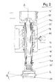
- the device illustrated in Fig. 1 has a housing 10 with a bearing 12 for drive shafts 14, 14 ', which act via gear elements 16, 16' on centering spindles 18, 18 ', which are aligned in the axial direction A. They wear tension bells 20, 20 'at their free ends, between which a lens L can be aligned and clamped.
- a motor M drives the two drive shafts 14, 14 'synchronously via a belt drive R and a torque divider 50.
- the gear elements 16 act on a coupling piece 34 at the lower end of the lower centering spindle 18, which is also called a clamping spindle. It can be adjusted in the axial direction A by means of a clamping device 24 in order to align a lens L and to hold it mechanically during grinding.
- the tensioning device 24 has a yoke 26 designed as a plate, in which a membrane piston 32 is arranged centrally for supporting the lower end of the tensioning spindle 18.
- the clamping device 24 is located in the lower, projecting part 100 of the housing 10, which has a guide bearing 22 for the clamping spindle 18.
- the tension bearing 22' has a cavity 78 which surrounds a sleeve 76 which is located concentrically on the fixed spindle 18 'or its guide sleeve 19'.
- the pressure in the cavity 78 can optionally be reduced or increased by means of an adjusting screw 80 acting as a piston.
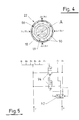
- the air bearing is shown in FIG. 3. This air bearing is arranged in the lower support part 100 of the housing 10 above the tensioning device 24.
- the air bearing has a sleeve 86 which tightly encloses the clamping spindle 18 or its guide sleeve 19.
- channels 90 are provided, which are preferably arranged axially parallel and / or partially in the form of a ring, in particular to form diametrically opposed air cushion fields. These can be pressurized or vented with compressed air via control openings A and B, preferably alternately with a pneumatically or electrically controlled (not shown) vibrator. The vibrations in the air bearing can be adjusted and optimized as required by frequency and pressure control. The smooth axial movement of the centering spindle 18 is then effected by pressurizing the diaphragm piston 32 of the tensioning device 24.
- a clamping bearing 22 which is formed by the sleeve 86 and a cavity 88 which surrounds the sleeve 86 and is connected via a connection to a pressure medium supply line, is used for clamping the clamping spindle 18.
- the sleeve deforms uniformly on all sides and clamps the clamping spindle in an exactly axially aligned manner.
- the centering spindles 18, 18 ' can be in one piece.
- the structure according to FIGS. 2 and 3 is preferred, according to which the fixed spindle 18 'has a guide sleeve 19' which is axially and radially supported via support bearings 74a, 74b with respect to the inner, actual rotary spindle 18 '.
- Corresponding support bearings 84a, 84b are provided for an outer sleeve 19 which surrounds the inner actual clamping spindle 18.
- the two centering spindles are a little bit axially displaceable due to wave springs 82, 82 ', so that the required clamping pressure can be set.
Landscapes
- Engineering & Computer Science (AREA)
- Chemical & Material Sciences (AREA)
- Ceramic Engineering (AREA)
- Inorganic Chemistry (AREA)
- Mechanical Engineering (AREA)
- Grinding And Polishing Of Tertiary Curved Surfaces And Surfaces With Complex Shapes (AREA)
Claims (9)
- Dispositif de centrage de lentilles optiques pour la fixation mécanique, en particulier lors du meulage des bords et de la réalisation de facettes, comportant un carter (10), muni d'un dispositif moteur pour l'entraînement de deux broches de centrage (18, 18'), alignées suivant la direction axiale (A) et dont les extrémités tournées l'une vers l'autre portent des cloches de serrage (20, 20'), entre lesquelles peut être serrée, pour son usinage, une lentille (L), au moyen d'un dispositif de serrage (24) agissant respectivement sur au moins une broche de centrage (18) ou une cloche de serrage (20), et dont chaque broche de centrage (18, 18') est disposée dans une première douille de guidage (19, 19') et prend appui sur celle-ci par l'intermédiaire de paliers d'appui (84a, 84b; 74a, 74b), caractérisé en ce qu'au moins l'une des deux douilles de guidage (19) est, de plus, guidée dans le carter (10) de la machine au moyen d'un ou plusieurs paliers à air (90), tandis que, pour le guidage dans le carter de machine, chaque palier à air (90) présente une deuxième douille de guidage mince (76, 86), qui entoure étroitement la broche de centrage (18, 18') concernée, ou sa douille de guidage (19, 19'), et qui, de son côté, est entourée par un volume creux (78, 88) pouvant recevoir un fluide sous pression, et forme ainsi un palier de serrage (22, 22').
- Dispositif suivant la revendication 1, caractérisé en ce que la broche supérieure de centrage (18') est également montée dans un palier à air.
- Dispositif suivant la revendication 1 ou la revendication 2, caractérisé en ce que le volume creux est réalisé, d'une part, par la deuxième douille de guidage (76, 86) et, d'autre part, par des parties de support en saillie (100, 100') du carter (10), ayant, dans son ensemble, une forme de C, ces parties de support maintenant alignés les paliers de serrage (22, 22') l'un par rapport à l'autre.
- Dispositif suivant l'une quelconque des revendications 1 à 3, caractérisé en ce que la pression dans le volume creux supérieur (78) peut être réglée ou réajustée au moyen d'un dispositif de réglage (80).
- Dispositif suivant l'une quelconque des revendications 1 à 4, caractérisé en ce qu'au moins le palier de serrage inférieur (22) présente un raccord (98) pour une conduite d'alimentation.
- Dispositif suivant au moins l'une des revendications 2 à 5, caractérisé en ce que les paliers à air (90) se faisant face peuvent être alimentés avec des pressions différentes.
- Dispositif suivant la revendication 6, caractérisé en ce que la fréquence et la pression de l'alimentation en pression peuvent être régulées ou réglées pneumatiquement et/ou électriquement.
- Dispositif suivant au moins l'une des revendications 1 à 7, caractérisé en ce que la paroi intérieure des douilles, ou de chacune des deuxièmes douilles, de guidage (76, 86) présente des canaux et/ou des poches (90), en particulier chaque fois sous la forme de quatre champs de coussins d'air.
- Dispositif suivant la revendication 8, caractérisé en ce que les canaux, ou poches, (90) sont réalisés sous forme de rainures parallèles à l'axe et/ou de parties de gorge annulaire.
Applications Claiming Priority (2)
| Application Number | Priority Date | Filing Date | Title |
|---|---|---|---|
| DE3744116A DE3744116C2 (de) | 1987-12-24 | 1987-12-24 | Maschine zum zentrierenden Randschleifen und Facettieren von optischen Linsen für die mechanische Halterung |
| DE3744116 | 1987-12-24 |
Publications (3)
| Publication Number | Publication Date |
|---|---|
| EP0322580A2 EP0322580A2 (fr) | 1989-07-05 |
| EP0322580A3 EP0322580A3 (en) | 1990-08-29 |
| EP0322580B1 true EP0322580B1 (fr) | 1993-05-05 |
Family
ID=6343616
Family Applications (1)
| Application Number | Title | Priority Date | Filing Date |
|---|---|---|---|
| EP88119935A Expired - Lifetime EP0322580B1 (fr) | 1987-12-24 | 1988-11-30 | Dispositif de centrage de lentilles optiques pour le montage mécanique, en particulier lors du meulage des bords et de facettes |
Country Status (3)
| Country | Link |
|---|---|
| US (1) | US4941291A (fr) |
| EP (1) | EP0322580B1 (fr) |
| DE (1) | DE3744116C2 (fr) |
Families Citing this family (10)
| Publication number | Priority date | Publication date | Assignee | Title |
|---|---|---|---|---|
| DE4214326A1 (de) * | 1992-04-30 | 1993-11-04 | Wernicke & Co Gmbh | Vorrichtung zur randbearbeitung von brillenglaesern |
| US6257968B1 (en) | 1998-12-16 | 2001-07-10 | National Optronics, Incorporated | Quick-release lens clamp pad assembly for use in eyeglass lens processing |
| US6243960B1 (en) | 1999-03-16 | 2001-06-12 | National Optronics, Incorporated | Tracer, clamp and object engager for holding and tracing a lens mount of an eyeglass frame, a lens, and/or a lens pattern, to reliably detect a shape thereof even when the shape includes high wrap |
| USD435053S (en) * | 1999-03-16 | 2000-12-12 | National Optronics, Incorporated | Eyeglass frame tracer |
| US6249991B1 (en) | 1999-03-17 | 2001-06-26 | National Optronics, Incorporated | Control system for eyeglass tracer |
| US6283825B1 (en) * | 1999-12-21 | 2001-09-04 | Johnson & Johnson Vision Products, Inc. | Automatic trimmer machine |
| DE10008710C2 (de) | 2000-02-24 | 2002-01-10 | Loh Optikmaschinen Ag | Vorrichtung zum zentrierenden Spannen von optischen Linsen für deren Randbearbeitung |
| US6519861B1 (en) * | 2000-05-04 | 2003-02-18 | Raytheon Company | Mechanical centering apparatus and method |
| DE102004049951A1 (de) * | 2004-10-13 | 2006-04-20 | Schneider Gmbh + Co. Kg | Hochdynamische Linsenbearbeitungsmaschine |
| CN100592125C (zh) * | 2006-12-20 | 2010-02-24 | 鸿富锦精密工业(深圳)有限公司 | 镜片压合治具 |
Family Cites Families (14)
| Publication number | Priority date | Publication date | Assignee | Title |
|---|---|---|---|---|
| US2508009A (en) * | 1946-09-11 | 1950-05-16 | Simonds Machine Co Inc | Edging machine |
| BE498786A (fr) * | 1950-01-24 | |||
| NL152774A (fr) * | 1950-01-24 | |||
| DE1004516B (de) * | 1956-03-02 | 1957-03-14 | Voigtlaender Ag | Verfahren und Maschine zum Zentrieren von optischen Linsen |
| US3143382A (en) * | 1961-06-06 | 1964-08-04 | Commissariat Energie Atomique | Aerodynamic bearing |
| US3359045A (en) * | 1966-05-20 | 1967-12-19 | Bendix Corp | Squeeze film bearing |
| US3599377A (en) * | 1968-07-22 | 1971-08-17 | Bausch & Lomb | Lens alignment using gas bearings |
| GB1310135A (en) * | 1970-07-22 | 1973-03-14 | Raphael O P | Method of and apparatus for filling spectacle lenses |
| DE2148102C3 (de) * | 1971-09-27 | 1979-07-05 | Ernst Leitz Wetzlar Gmbh, 6300 Lahn- Wetzlar | Verfahren zum Zentrieren von Linsen |
| DK338978A (da) * | 1977-08-02 | 1979-02-03 | Automated Optics | Kontaktlinse samt fremgangsmaade og maskine til fremstilling af saadanne linser |
| DE2756407A1 (de) * | 1977-12-17 | 1979-06-21 | Prontor Werk Gauthier Gmbh | Maschine zum randschleifen und facettieren von optischen linsen |
| DE3139873C2 (de) * | 1981-10-07 | 1983-11-10 | Prontor-Werk Alfred Gauthier Gmbh, 7547 Wildbad | Maschine zum Randschleifen und Facettieren von optischen Linsen |
| FR2553323B1 (fr) * | 1983-10-18 | 1986-07-25 | Essilor Int | Procede et machine pour le biseautage ou rainurage d'une lentille ophtalmique |
| DE3526539C1 (de) * | 1985-07-24 | 1986-11-13 | Erwin 7611 Nordrach Junker | Verfahren zur Praezisionsschnellspannung von rotationssymmetrischen Werkstuecken sowie Praezisionsschnellspannvorrichtung zur Durchfuehrung des Verfahrens |
-
1987
- 1987-12-24 DE DE3744116A patent/DE3744116C2/de not_active Expired - Fee Related
-
1988
- 1988-11-30 EP EP88119935A patent/EP0322580B1/fr not_active Expired - Lifetime
- 1988-12-23 US US07/289,903 patent/US4941291A/en not_active Expired - Fee Related
Also Published As
| Publication number | Publication date |
|---|---|
| DE3744116C2 (de) | 1994-10-13 |
| EP0322580A3 (en) | 1990-08-29 |
| DE3744116A1 (de) | 1989-07-06 |
| US4941291A (en) | 1990-07-17 |
| EP0322580A2 (fr) | 1989-07-05 |
Similar Documents
| Publication | Publication Date | Title |
|---|---|---|
| DE19680863B4 (de) | Verfahren zum Herstellen von optischen Oberflächen sowie Bearbeitungsmaschine zur Durchführung des Verfahrens | |
| EP0322580B1 (fr) | Dispositif de centrage de lentilles optiques pour le montage mécanique, en particulier lors du meulage des bords et de facettes | |
| DE19825698B4 (de) | Bandschleifmaschine | |
| EP0411346A2 (fr) | Machine de superfinition pour rodage, superfinition ou polissage | |
| EP1742762B1 (fr) | Dispositif pour produire des microstructures | |
| DE1577366B1 (de) | Rundschleifmaschine zur gleichzeitigen Bearbeitung von zwei rotierenden Werkstuecken mit einem rotierenden Werkzeug | |
| EP0278037A1 (fr) | Machine pour centrer l'équilibrage de corps en rotation | |
| EP0322579B1 (fr) | Dispositif de centrage de lentilles optiques pour le montage mécanique, en particulier lors du meulage des bords et de facettes | |
| EP0323572B1 (fr) | Dispositif de centrage de lentilles optiques pour le montage mécanique, en particulier lors du moulage des bords et de facettes | |
| DE69400964T2 (de) | Haltevorrichtung für torische linse | |
| DE3918365A1 (de) | Ultra-praezisionsschleifmaschine | |
| EP0322578A2 (fr) | Dispositif de centrage de lentilles optiques pour le montage mécanique, en particulier lors du meulage des bords et de facettes | |
| DE19531506C1 (de) | Schleifmaschine, insbesondere Rundschleifmaschine | |
| DE4137071A1 (de) | Fuehrung zum spitzenlosen, zentrischen, radialen fuehrnen von axial bewegten staeben | |
| DE4120338C1 (en) | Machine for external cylindrical grinding - has rotating electro-magnetic chuck with grinding wheel and support unit which allows unit to pivot about point | |
| CH671177A5 (fr) | ||
| DE3918847C2 (fr) | ||
| DE102008011215A1 (de) | Vorrichtung zur mechanischen Finishbearbeitung von Laufflächen an Wälzlagerringen | |
| EP4271538B1 (fr) | Procédé et dispositif d'usinage de précision de lentilles axicon, machine d'usinage de précision appropriée et utilisation y relative | |
| DE3617790A1 (de) | Ultraschallbearbeitungsmaschine | |
| DE10303215B4 (de) | Verfahren und Honmaschine zum Innenhonen von Werkstücken | |
| CH720778B1 (de) | Rundschleifmaschinenzubehör zum spitzenlosen Schleifen auf einer Rundschleifmaschine | |
| DE8915458U1 (de) | Feinbearbeitungsmaschine zum Läppen, Feinschleifen oder Polieren | |
| DE4314152C2 (de) | Vorrichtung zur Beseitigung der Schwingungsneigung eines Werkstückscheiben- oder Werkzeugträgers in Maschinen zur einseitigen Bearbeitung der Oberflächen von Halbleiterscheiben | |
| EP0829326A1 (fr) | Procédé et appareil pour la fabrication des corps rotatives |
Legal Events
| Date | Code | Title | Description |
|---|---|---|---|
| PUAI | Public reference made under article 153(3) epc to a published international application that has entered the european phase |
Free format text: ORIGINAL CODE: 0009012 |
|
| AK | Designated contracting states |
Kind code of ref document: A2 Designated state(s): CH ES FR GB IT LI |
|
| PUAL | Search report despatched |
Free format text: ORIGINAL CODE: 0009013 |
|
| AK | Designated contracting states |
Kind code of ref document: A3 Designated state(s): CH ES FR GB IT LI |
|
| 17P | Request for examination filed |
Effective date: 19901002 |
|
| 17Q | First examination report despatched |
Effective date: 19920318 |
|
| GRAA | (expected) grant |
Free format text: ORIGINAL CODE: 0009210 |
|
| AK | Designated contracting states |
Kind code of ref document: B1 Designated state(s): CH ES FR GB IT LI |
|
| PG25 | Lapsed in a contracting state [announced via postgrant information from national office to epo] |
Ref country code: ES Free format text: THE PATENT HAS BEEN ANNULLED BY A DECISION OF A NATIONAL AUTHORITY Effective date: 19930505 |
|
| ITF | It: translation for a ep patent filed | ||
| ET | Fr: translation filed | ||
| GBT | Gb: translation of ep patent filed (gb section 77(6)(a)/1977) |
Effective date: 19930809 |
|
| PLBE | No opposition filed within time limit |
Free format text: ORIGINAL CODE: 0009261 |
|
| STAA | Information on the status of an ep patent application or granted ep patent |
Free format text: STATUS: NO OPPOSITION FILED WITHIN TIME LIMIT |
|
| 26N | No opposition filed | ||
| PGFP | Annual fee paid to national office [announced via postgrant information from national office to epo] |
Ref country code: GB Payment date: 19941122 Year of fee payment: 7 |
|
| PGFP | Annual fee paid to national office [announced via postgrant information from national office to epo] |
Ref country code: CH Payment date: 19951013 Year of fee payment: 8 |
|
| PGFP | Annual fee paid to national office [announced via postgrant information from national office to epo] |
Ref country code: FR Payment date: 19951020 Year of fee payment: 8 |
|
| PG25 | Lapsed in a contracting state [announced via postgrant information from national office to epo] |
Ref country code: GB Effective date: 19951130 |
|
| GBPC | Gb: european patent ceased through non-payment of renewal fee |
Effective date: 19951130 |
|
| PG25 | Lapsed in a contracting state [announced via postgrant information from national office to epo] |
Ref country code: LI Effective date: 19961130 Ref country code: CH Effective date: 19961130 |
|
| REG | Reference to a national code |
Ref country code: CH Ref legal event code: PL |
|
| PG25 | Lapsed in a contracting state [announced via postgrant information from national office to epo] |
Ref country code: FR Effective date: 19970731 |
|
| REG | Reference to a national code |
Ref country code: FR Ref legal event code: ST |
|
| PG25 | Lapsed in a contracting state [announced via postgrant information from national office to epo] |
Ref country code: IT Free format text: LAPSE BECAUSE OF NON-PAYMENT OF DUE FEES;WARNING: LAPSES OF ITALIAN PATENTS WITH EFFECTIVE DATE BEFORE 2007 MAY HAVE OCCURRED AT ANY TIME BEFORE 2007. THE CORRECT EFFECTIVE DATE MAY BE DIFFERENT FROM THE ONE RECORDED. Effective date: 20051130 |