EP0411346A2 - Machine de superfinition pour rodage, superfinition ou polissage - Google Patents
Machine de superfinition pour rodage, superfinition ou polissage Download PDFInfo
- Publication number
- EP0411346A2 EP0411346A2 EP90113033A EP90113033A EP0411346A2 EP 0411346 A2 EP0411346 A2 EP 0411346A2 EP 90113033 A EP90113033 A EP 90113033A EP 90113033 A EP90113033 A EP 90113033A EP 0411346 A2 EP0411346 A2 EP 0411346A2
- Authority
- EP
- European Patent Office
- Prior art keywords
- working
- disk
- lapping
- finishing machine
- disc
- Prior art date
- Legal status (The legal status is an assumption and is not a legal conclusion. Google has not performed a legal analysis and makes no representation as to the accuracy of the status listed.)
- Withdrawn
Links
Images


Classifications
-
- B—PERFORMING OPERATIONS; TRANSPORTING
- B24—GRINDING; POLISHING
- B24B—MACHINES, DEVICES, OR PROCESSES FOR GRINDING OR POLISHING; DRESSING OR CONDITIONING OF ABRADING SURFACES; FEEDING OF GRINDING, POLISHING, OR LAPPING AGENTS
- B24B57/00—Devices for feeding, applying, grading or recovering grinding, polishing or lapping agents
- B24B57/02—Devices for feeding, applying, grading or recovering grinding, polishing or lapping agents for feeding of fluid, sprayed, pulverised, or liquefied grinding, polishing or lapping agents
-
- B—PERFORMING OPERATIONS; TRANSPORTING
- B24—GRINDING; POLISHING
- B24B—MACHINES, DEVICES, OR PROCESSES FOR GRINDING OR POLISHING; DRESSING OR CONDITIONING OF ABRADING SURFACES; FEEDING OF GRINDING, POLISHING, OR LAPPING AGENTS
- B24B37/00—Lapping machines or devices; Accessories
- B24B37/04—Lapping machines or devices; Accessories designed for working plane surfaces
Definitions
- the invention relates to a finishing machine for lapping, fine grinding or polishing.
- Finishing machines for this purpose are known with two separately drivable, ring-shaped, vertical-axis working disks, with a drivable, inner and preferably a stationary, outer pin ring being provided in the area of the lower disk, between which holders for workpiece machining are arranged, which are used for their planetary movement engage the disk axis in both pin rings by means of teeth, preferably in a cantilever or portal construction with a horizontally movable upper working disk, a control circuit being provided to influence the axial force acting on the upper working disk.
- the task of the finishing machine is the constant control of the preselected engagement pressure between the active partners during machining and dressing, as well as the automatic height adjustment of the working disks and setting of optimal speed ratios during machining and dressing with the help of a program stored in the controller memory to achieve reproducible work results in the process-inherent accuracy limit range with a high degree of automation of the machine and a lower required operator qualification.
- the finishing machine for lapping, fine grinding or polishing according to the preamble of claim 1 according to the invention is characterized in that the axial force can be derived via force transducers on the underframe of the machine with medium or direct contact with the lower working disc, the upper one , preferably pendulum-mounted working disc is pneumatically or hydraulically actuated and the axially supported bearing unit of the lower working disc, which is supported by force transducers on the machine base frame, is secured against twisting by preferably thin strips arranged in a plane parallel to the working plane and braced between the frame and the bearing unit.
- a signal which is dependent on the axial actual force is thus generated by means of the aforementioned high-resolution measuring system, for example based on a strain gauge, located in the base of the machine.
- This signal is compared with a signal that corresponds to the axial nominal force.
- the difference signal is the control deviation. It changes the pressure within the load unit in such a way that the pressure of engagement between the active partners remains constant within narrowly specified tolerance limits; an essential criterion for achieving reproducible process relationships.
- the height of the upper quill-guided working disc adjustable in height using a pneumatic or hydraulic lifting and loading device secured by means of guide rods, but the height of the lower working disc can also be changed using a quill adjustment or several axially parallel and mutually synchronized screw drives with a cross-beam, in order to maintain constant wear to enable the height of the active surface.
- the finishing machine is characterized in that the stepless adjustment and optional combination of the speeds of the two working disks and the inner and optionally outer pin ring in the area of the lower working disk and thus the planetary movement of the workpiece holder for workpiece machining or the dressing rings is program-controlled .
- this makes it difficult to set suitable speeds when machining and dressing with a program stored in the controller's memory), which involves the user-friendly entry of recommended parameters - the type of relative movement of the active partners, - the relative speed of the active partners and - the position of the parts within the holder or the size of the dressing rings ensures optimal movement conditions.
- Entering data of this type offers the advantage that the reproducibility and quality of the work and dressing results are independent of the qualifications and experience of the machine operator.
- the machine structure 1 can be seen with the axially movable quill 2 and the hollow shaft 3 which supports it and serves for torque transmission.
- the sleeve 2 is received in a form-fitting manner in the bearing area 4 of the hollow shaft 3 which is supported on the machine structure 1 via the roller bearings 6 and 7.
- the sleeve 2, on which the upper working disk 8 is suspended in a pendulum manner via its spherical bearing 5, is set in rotation by the rim drive 9 via the hollow shaft 3.
- the lifting and loading device consisting of two hydraulic cylinders 10 serves to apply the axial pressure via the crossbar 11 with the support bearing 12, while the torque resulting from the bearing friction is absorbed via the guide rods 13.
- the lapping mixture when fed via the stripping device 14 with strippers 15, enters the ring channel 16 and through bores 17 in the upper working disk 8 into the active zone.
- the drive motor 18 of the scraper device 14 is arranged on the machine structure 1 in such a way that rotation about the axis of the upper working disk 8 is suppressed, but its pendulum movement is also carried out.
- the machine structure 1 as not shown in detail here, can be made in portal construction, e.g. executed according to DE-PS 24 42 081 and thus can be moved horizontally with respect to the machine base 19 with the bearing unit and the upper working disk 8.
- the machine base 19 can be seen with the hollow shaft 20 and the height-adjustable guide housing 21.
- the hollow shaft 20 which serves to drive the lower working disk 22 is received by the roller bearings 23 and 24 and the guide housing 21 is mounted in a height-adjustable manner with guide rods 27 by means of a plurality of screw thread drives 25, which are arranged equidistantly from the central axis and are synchronized, with a crossbar 26.
- the hollow shaft 20 is via the belt drive 28 rotatable.
- a height adjustment of the lower working disc 22 in this way has the advantage that a lowering of the working height as a result of the disc wear can be compensated for.
- the possibility of keeping the height of the active surface of the lower working disk 22 largely constant is a necessary prerequisite for to see the automatability of the machine loading.
- the adjustability of the height of the lower work wheel is also suitable for integrating wear measurement and the subsequent removal of unevenness in the work wheel, which is associated with a deterioration in the achievable part shape accuracy, with the additional use of a radially arranged measuring and twisting device in an automatic sequence.
- the bearing unit 29 of the lower working disc 22 is supported on the base frame 19 of the machine by force transducers 30, the bearing unit 29 being secured against rotation in a plane parallel to the working plane by means of thin bands 31 braced between the frame 19 and the bearing unit 29.
- the force transducers 30 on the base frame 19 are used for constant control of the axial force to be applied by the lifting and loading device 10.
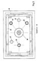
- FIG. 2 also shows the inner pin ring 33 driven from 32 and the outer pin ring 34 which is stationary here and has a workpiece holder 35 for workpieces 36, the holders 35 engaging in the inner and outer pin rings 33, 34.
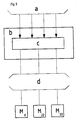
- the regulation of the axial force F is then shown schematically in FIG.
- the upper and lower working disks 8 and 22 can be seen in the machine structure 1 and the machine base frame 19 with workpieces 36 between them, the force transducer 30 in the base frame 19 and the lifting and loading device 10 as hydraulic cylinders in the structure 1 with the signal converter 37
- a hydraulic or pneumatic loading unit 10 generates an axially acting force due to the differential pressure ⁇ p H prevailing in the cylinder.
- This force F which acts as the actual force, acts on the upper working disk 8 in such a way that, depending on the contact surface between the active partners, a characteristic engagement pressure Pe results.
- the actual force introduced into the bearing system of the lower working disk 22 in this way is derived via pressure force transducers 30 arranged preferably equidistant from the axis of the working disks in the underframe 19 of the machine.
- a summatory voltage signal u act which is proportional to the actual force, is generated and is compared with a voltage signal u soll corresponding to the nominal axial force.
- the difference signal ⁇ u is the control deviation. It changes the differential pressure ⁇ p H within the pressure cylinder - load unit 10 - in such a way that the engagement pressure Pe remains constant within narrowly specified limits.
- the arrangement of the pressure force transducers 30 in the base frame 19 of the machine has the advantage over known solutions that the flow of force guided through the effective zone is recorded in an unadulterated manner.
- the measurement result is therefore not impaired by friction losses and stick-slip effects at the bearing points of the upper working disk or within the loading device.
- the control concept therefore provides for the user-guided input of recommended characteristic values, which are converted into speed control signals of the motors M of the two working disks 8 and 22 and of the inner pin ring 33 with the aid of a program stored in the control's memory without further operator intervention.
- the arbitrary selection of the characteristic values allows, in particular, the stepless setting and combination of the speeds in such a way that there are optimal movement conditions between the active partners during machining and dressing.
Landscapes
- Engineering & Computer Science (AREA)
- Mechanical Engineering (AREA)
- Finish Polishing, Edge Sharpening, And Grinding By Specific Grinding Devices (AREA)
Applications Claiming Priority (4)
| Application Number | Priority Date | Filing Date | Title |
|---|---|---|---|
| DE19893925274 DE3925274A1 (de) | 1989-07-31 | 1989-07-31 | Feinbearbeitungsmaschine zum laeppen, feinschleifen oder polieren |
| DE3925274 | 1989-07-31 | ||
| DE8915458U | 1989-07-31 | ||
| DE8915458U DE8915458U1 (de) | 1989-07-31 | 1989-07-31 | Feinbearbeitungsmaschine zum Läppen, Feinschleifen oder Polieren |
Publications (2)
| Publication Number | Publication Date |
|---|---|
| EP0411346A2 true EP0411346A2 (fr) | 1991-02-06 |
| EP0411346A3 EP0411346A3 (en) | 1991-04-10 |
Family
ID=25883567
Family Applications (1)
| Application Number | Title | Priority Date | Filing Date |
|---|---|---|---|
| EP19900113033 Withdrawn EP0411346A3 (en) | 1989-07-31 | 1990-07-07 | Precision grinding machine for lapping, precision grinding or polishing |
Country Status (2)
| Country | Link |
|---|---|
| US (1) | US5197230A (fr) |
| EP (1) | EP0411346A3 (fr) |
Cited By (1)
| Publication number | Priority date | Publication date | Assignee | Title |
|---|---|---|---|---|
| CN114888651A (zh) * | 2022-04-25 | 2022-08-12 | 长春理工大学 | 一种飞轮盘半制品磨抛修复装置和修复方法 |
Families Citing this family (15)
| Publication number | Priority date | Publication date | Assignee | Title |
|---|---|---|---|---|
| US5329732A (en) | 1992-06-15 | 1994-07-19 | Speedfam Corporation | Wafer polishing method and apparatus |
| US5733175A (en) | 1994-04-25 | 1998-03-31 | Leach; Michael A. | Polishing a workpiece using equal velocity at all points overlapping a polisher |
| US5607341A (en) | 1994-08-08 | 1997-03-04 | Leach; Michael A. | Method and structure for polishing a wafer during manufacture of integrated circuits |
| US5556322A (en) * | 1995-09-05 | 1996-09-17 | Sommer & Maca Industries, Inc. | Pneumatic mechanism for the application of uniform pressure to a mechanically adjustable spindle |
| US5697832A (en) * | 1995-10-18 | 1997-12-16 | Cerion Technologies, Inc. | Variable speed bi-directional planetary grinding or polishing apparatus |
| US5738568A (en) * | 1996-10-04 | 1998-04-14 | International Business Machines Corporation | Flexible tilted wafer carrier |
| US5816892A (en) * | 1997-02-06 | 1998-10-06 | Cobra Machine Tool Co., Inc. | Positioning control for combined milling machine and internally positioned grinding wheel |
| US5810648A (en) * | 1997-03-05 | 1998-09-22 | Hmt Technology Corporation | Device for texturing a disc substrate |
| US5928067A (en) * | 1997-10-14 | 1999-07-27 | Beloit Technologies, Inc. | Headbox apron finishing and lapping device |
| US6254463B1 (en) | 1998-10-09 | 2001-07-03 | International Business Machines Corporation | Chemical planar head dampening system |
| JP2000127033A (ja) * | 1998-10-27 | 2000-05-09 | Speedfam-Ipec Co Ltd | 研磨装置 |
| US7364495B2 (en) * | 2002-03-28 | 2008-04-29 | Etsu Handotai Co., Ltd. | Wafer double-side polishing apparatus and double-side polishing method |
| US6875076B2 (en) | 2002-06-17 | 2005-04-05 | Accretech Usa, Inc. | Polishing machine and method |
| IT1396287B1 (it) * | 2009-09-28 | 2012-11-16 | Biesse Spa | Distributore in continuo |
| US20120003900A1 (en) * | 2010-07-01 | 2012-01-05 | Artisan Industries Inc. | Apparatus and Method for Refinishing a Surface In-Situ |
Family Cites Families (10)
| Publication number | Priority date | Publication date | Assignee | Title |
|---|---|---|---|---|
| DE218300C (fr) * | ||||
| CH244291A (de) * | 1943-11-27 | 1946-09-15 | Ag Ryter | Maschine zum Polieren der Stirnflächen von Werksteinen. |
| US2973605A (en) * | 1959-11-09 | 1961-03-07 | Carman Lab Inc | Lapping machine |
| DE1577322A1 (de) * | 1966-11-26 | 1970-01-08 | Deutsche Edelstahlwerke Ag | Vorrichtung an Ein- oder Zweischeiben-Horizontallaeppmaschinen |
| DE2440978C3 (de) * | 1974-08-27 | 1979-05-17 | Jmj-Werkzeugmaschinen Gmbh Fuer Feinbearbeitung, 4020 Mettmann | Dosiervorrichtung für Läppmittel |
| DE2442081C3 (de) * | 1974-09-03 | 1979-11-15 | Jmj-Werkzeugmaschinen Gmbh Fuer Feinbearbeitung, 4020 Mettmann | Läppmaschine |
| JPS55144958A (en) * | 1979-04-18 | 1980-11-12 | Tsutomu Kimura | Lapping machine |
| US4315383A (en) * | 1980-05-13 | 1982-02-16 | Spitfire Tool & Machine, Co. Inc. | Inner gear drive for abrading machines |
| FR2564360B1 (fr) * | 1984-05-21 | 1986-10-17 | Crismatec | Machine d'usinage double face et dispositif de transmission de courant et de fluide entre une structure tournante et une structure non tournante |
| JPS63120077A (ja) * | 1986-11-08 | 1988-05-24 | Otani Reiji | ロボツト装填・装出用ラツピング及びポリシングマシン駆動方法 |
-
1990
- 1990-07-07 EP EP19900113033 patent/EP0411346A3/de not_active Withdrawn
- 1990-07-16 US US07/553,727 patent/US5197230A/en not_active Expired - Fee Related
Cited By (1)
| Publication number | Priority date | Publication date | Assignee | Title |
|---|---|---|---|---|
| CN114888651A (zh) * | 2022-04-25 | 2022-08-12 | 长春理工大学 | 一种飞轮盘半制品磨抛修复装置和修复方法 |
Also Published As
| Publication number | Publication date |
|---|---|
| US5197230A (en) | 1993-03-30 |
| EP0411346A3 (en) | 1991-04-10 |
Similar Documents
| Publication | Publication Date | Title |
|---|---|---|
| EP0411346A2 (fr) | Machine de superfinition pour rodage, superfinition ou polissage | |
| DE10234707B4 (de) | Verfahren und Vorrichtung zum Schleifen eines rotationssymmetrischen Maschinenbauteils | |
| DE2658970C3 (de) | Kurbelwellenfräsmaschine | |
| CH620389A5 (fr) | ||
| WO2004014606A1 (fr) | Procede et dispositif de rectification externe et interne d'un composant de machine a symetrie de revolution presentant un alesage longitudinal | |
| WO2003103896A1 (fr) | Machine d'usinage fin par pierrage | |
| DE69811420T2 (de) | Schleifmaschine und Verfahren | |
| DE102016006791A1 (de) | Maschine zur Bearbeitung von Werkstücken in optischer Qualität | |
| EP0159383B1 (fr) | Machine pour meuler les surfaces toriques de lentilles optiques | |
| DE2208508A1 (de) | Waagerecht-tiefbohrmaschine | |
| EP0322580B1 (fr) | Dispositif de centrage de lentilles optiques pour le montage mécanique, en particulier lors du meulage des bords et de facettes | |
| DE2818667A1 (de) | Werkzeugmaschine zum raeumlichen polieren mit magnetschleifpulver im magnetfeld von werkstuecken, die die form eines rotationskoerpers besitzen | |
| DE1577390C3 (de) | Einrichtung zum Hin- und Herbewegen der Schleifkörperhalterung einer Superfinish- oder Honmaschine | |
| EP1955808A1 (fr) | Meuleuse destinée au meulage de pièces à usiner entre des pointes ainsi qu'au meulage sans pointe et procédé de meulage | |
| WO2000066309A1 (fr) | Affuteuse pour lames de scie presentant une tete de meule porteuse d'au moins un disque de meule et d'au moins une tige de meulage | |
| DE3925274A1 (de) | Feinbearbeitungsmaschine zum laeppen, feinschleifen oder polieren | |
| DE907238C (de) | Selbsttaetige Kopierfraes- und Schleifmaschine | |
| CH647431A5 (en) | Apparatus and process for the cold rolling of sections by rolling on the circumference of a simultaneously rotating workpiece | |
| DE3936200C1 (fr) | ||
| DE3918847C2 (fr) | ||
| DE3343710C2 (fr) | ||
| DE4131752A1 (de) | Verfahren zum einseitigen flaechenbearbeiten von werkstuecken | |
| DE8915458U1 (de) | Feinbearbeitungsmaschine zum Läppen, Feinschleifen oder Polieren | |
| DE3441305C2 (fr) | ||
| DE891815C (de) | Laeppmaschine und -verfahren |
Legal Events
| Date | Code | Title | Description |
|---|---|---|---|
| PUAI | Public reference made under article 153(3) epc to a published international application that has entered the european phase |
Free format text: ORIGINAL CODE: 0009012 |
|
| AK | Designated contracting states |
Kind code of ref document: A2 Designated state(s): CH DE ES FR GB IT LI |
|
| PUAL | Search report despatched |
Free format text: ORIGINAL CODE: 0009013 |
|
| AK | Designated contracting states |
Kind code of ref document: A3 Designated state(s): CH DE ES FR GB IT LI |
|
| 17P | Request for examination filed |
Effective date: 19910413 |
|
| 17Q | First examination report despatched |
Effective date: 19920921 |
|
| STAA | Information on the status of an ep patent application or granted ep patent |
Free format text: STATUS: THE APPLICATION IS DEEMED TO BE WITHDRAWN |
|
| 18D | Application deemed to be withdrawn |
Effective date: 19930408 |