EP0322628A2 - Appareil à déposer des étoffes muni d'un dispositif de coupe - Google Patents
Appareil à déposer des étoffes muni d'un dispositif de coupe Download PDFInfo
- Publication number
- EP0322628A2 EP0322628A2 EP88120769A EP88120769A EP0322628A2 EP 0322628 A2 EP0322628 A2 EP 0322628A2 EP 88120769 A EP88120769 A EP 88120769A EP 88120769 A EP88120769 A EP 88120769A EP 0322628 A2 EP0322628 A2 EP 0322628A2
- Authority
- EP
- European Patent Office
- Prior art keywords
- knife wheel
- machine according
- laying machine
- cutting
- fabric laying
- Prior art date
- Legal status (The legal status is an assumption and is not a legal conclusion. Google has not performed a legal analysis and makes no representation as to the accuracy of the status listed.)
- Withdrawn
Links
- 239000004744 fabric Substances 0.000 title claims abstract description 38
- 230000002093 peripheral effect Effects 0.000 claims description 8
- 238000006073 displacement reaction Methods 0.000 claims description 7
- 230000001154 acute effect Effects 0.000 claims description 3
- 239000000463 material Substances 0.000 claims description 3
- 238000010276 construction Methods 0.000 abstract description 4
- 230000015572 biosynthetic process Effects 0.000 description 1
- 230000000694 effects Effects 0.000 description 1
- 238000005096 rolling process Methods 0.000 description 1
- 238000010008 shearing Methods 0.000 description 1
Images


Classifications
-
- B—PERFORMING OPERATIONS; TRANSPORTING
- B26—HAND CUTTING TOOLS; CUTTING; SEVERING
- B26D—CUTTING; DETAILS COMMON TO MACHINES FOR PERFORATING, PUNCHING, CUTTING-OUT, STAMPING-OUT OR SEVERING
- B26D1/00—Cutting through work characterised by the nature or movement of the cutting member or particular materials not otherwise provided for; Apparatus or machines therefor; Cutting members therefor
- B26D1/01—Cutting through work characterised by the nature or movement of the cutting member or particular materials not otherwise provided for; Apparatus or machines therefor; Cutting members therefor involving a cutting member which does not travel with the work
- B26D1/12—Cutting through work characterised by the nature or movement of the cutting member or particular materials not otherwise provided for; Apparatus or machines therefor; Cutting members therefor involving a cutting member which does not travel with the work having a cutting member moving about an axis
- B26D1/14—Cutting through work characterised by the nature or movement of the cutting member or particular materials not otherwise provided for; Apparatus or machines therefor; Cutting members therefor involving a cutting member which does not travel with the work having a cutting member moving about an axis with a circular cutting member, e.g. disc cutter
- B26D1/20—Cutting through work characterised by the nature or movement of the cutting member or particular materials not otherwise provided for; Apparatus or machines therefor; Cutting members therefor involving a cutting member which does not travel with the work having a cutting member moving about an axis with a circular cutting member, e.g. disc cutter coacting with a fixed member
- B26D1/205—Cutting through work characterised by the nature or movement of the cutting member or particular materials not otherwise provided for; Apparatus or machines therefor; Cutting members therefor involving a cutting member which does not travel with the work having a cutting member moving about an axis with a circular cutting member, e.g. disc cutter coacting with a fixed member for thin material, e.g. for sheets, strips or the like
-
- A—HUMAN NECESSITIES
- A41—WEARING APPAREL
- A41H—APPLIANCES OR METHODS FOR MAKING CLOTHES, e.g. FOR DRESS-MAKING OR FOR TAILORING, NOT OTHERWISE PROVIDED FOR
- A41H43/00—Other methods, machines or appliances
- A41H43/005—Cloth spreading or piling apparatus in view of its cutting
-
- D—TEXTILES; PAPER
- D06—TREATMENT OF TEXTILES OR THE LIKE; LAUNDERING; FLEXIBLE MATERIALS NOT OTHERWISE PROVIDED FOR
- D06H—MARKING, INSPECTING, SEAMING OR SEVERING TEXTILE MATERIALS
- D06H7/00—Apparatus or processes for cutting, or otherwise severing, specially adapted for the cutting, or otherwise severing, of textile materials
- D06H7/02—Apparatus or processes for cutting, or otherwise severing, specially adapted for the cutting, or otherwise severing, of textile materials transversely
Definitions
- the invention relates to a fabric laying machine with a guide along which a fabric web runs in the delivery direction and with a cutting device comprising a counter-cutting blade arranged on one side of the guide and extending transversely to the delivery direction, and a counter-cutting blade arranged on the opposite side with its axis of rotation, which is transverse to the delivery direction and by means of a feed drive, the knife wheel can be moved across the width of the guide, which rotates to cut through the web of material and, with a circumferential outer cutting area, bears against an edge of the counter-cutting blade running transversely to the direction of extension.
- the edge of the counter-cutting blade runs at an angle to a plane of the cutting blade which is perpendicular to the axis of rotation and lies almost point-like on the outer circumference of the cutting blade.
- the edge runs at an angle to a tangent to the knife wheel at the point of contact between the edge and the knife wheel, so that a cutting gap is formed between the outer circumference of the knife wheel and the edge protruding therefrom.
- a web of fabric inserted into this cutting gap is created by the shearing action between the knife wheel and the edge cut, with this arrangement with a counter-cutting blade only cutting in one direction is possible.
- Such an alignment of the edge relative to the knife wheel has the disadvantage that an arrangement of the counter-cutting blade with such an aligned edge requires a relatively high level of design effort, and that due to the punctiform contact of the knife wheel on the edge, high wear both in the area of the knife wheel and occurs in the area of the edge.
- the invention is therefore based on the object of improving a fabric laying machine of the generic type in such a way that the cutting device is constructed with the least possible wear and tear and is as simple as possible in terms of construction.
- the cutting area is a cutting surface which is essentially perpendicular to the axis of rotation of the knife wheel and that the cutting surface and the edge are aligned parallel to one another and abut one another in a line.
- a structurally particularly simple solution in which the advantages according to the invention come into play to the full extent, provides that the cutting surface is an outer region of an end surface of the same that runs perpendicular to the axis of rotation of the knife wheel.
- the edge extends parallel to the transverse direction, along which the knife wheel can be moved, so that the cutting gap formed between the knife wheel and the edge in both Directions is the same size and consequently the same cutting conditions can be used in both directions.
- the counter-cutting blade should be movable together with the knife wheel, as is the case in the prior art, or whether the counter-blade should be arranged in a stationary manner.
- the counter blade is a machine-fixed and extending parallel to the transverse direction over the guide bar, so that only the knife wheel can be moved in the transverse direction relative to the counter blade.
- This stationary arrangement of the counterblade also favors the cutting action, since the web of material which is stationary in the fabric-laying machine can remain on the counterblade and the knife wheel is displaced relative to both.
- the edge it has proven to be advantageous if it is formed by a surface facing the guide and a front surface that is transverse to the direction of extension, the surface and the front surface advantageously enclosing an angle of less than or equal to 90 ° with one another.
- the cutting surface and the front surface enclose an acute angle, which is preferably in the range of a few degrees. This ensures without major design measures that the cutting surface always lies directly against the edge and that an in-between between the edge and the cutting surface cannot arise due to inaccuracies in the construction or operation.
- the knife wheel has proven to be advantageous to ensure adequate and constant contact of the knife wheel with its cutting surface when the knife wheel is spring-loaded against the edge.
- a circumferential surface of the knife wheel forms an angle of ⁇ 90 ° with the cutting surface.
- the knife wheel is a so-called scissor-cut knife wheel.
- the circumferential surface of the knife wheel forms an angle of approximately 90 ° with the cutting surface, in this case it is a so-called roller shear knife wheel.
- the simplest possibility of this type provides that the knife wheel can be driven directly by a motor.
- the knife wheel can be driven by a trailing drive, ie that the knife wheel itself is displaced in the transverse direction by a drive, and the knife wheel itself is then also indirectly driven by this displacement of the knife wheel. This ensures that the moving parts have a low mass and in particular that the heavy drive does not have to be moved, so that rapid cutting is possible.
- Such a traction drive can be designed in a wide variety of ways.
- the simplest form of such a traction drive provides that it comprises a towing member which is fixed to the machine outside the guide and extends parallel to it in the transverse direction, and such a towing member can be designed, for example, as a rope, chain or rack.
- the knife wheel itself could also be driven only by frictional engagement, it has proven to be expedient if the knife wheel is driven by a trailing wheel which engages positively in the towing member and which in turn is then connected to the knife wheel.
- the knife wheel is held on a slide which can be displaced along a machine-fixed guideway.
- this guideway is a guide bar which is encompassed by the slide, preferably the carriage with rollers runs on this guide bar.
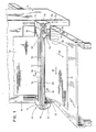
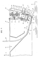
- FIG. 1 shows a laying unit, designated as a whole by 10, of a fabric laying machine 12, which is held on a machine frame 16 of the fabric laying machine so as to be vertically displaceable in the direction of arrow 14.
- an inlet funnel 18 is provided, through which a fabric web 20 comes into the laying from a preselected roller (not shown in the drawing) unit 10 is insertable.
- This feed hopper 18 is followed by a laying scoop 22, which forms a fabric guide surface 24 for the fabric web 20, along which it is guided in the laying unit until it leaves the laying unit 10 in the region of a laying edge 26 and in a curve 28 in the direction of a Layer stack 30 falls, in which the fabric web 20 is then designed as the top layer 32.
- a strip 34 is provided below the web guide surface 24 as part of an embodiment of a cutting device according to the invention, which extends parallel to the spreading edge 26 of the spreading blade 22 and protrudes beyond the spreading edge 26 in the spreading direction 36 of the cloth web 20.
- This bar 34 extends in the transverse direction 39 to the laying direction 36 over an entire width of the laying edge 26.
- the bar 34 has a surface 37 with which it faces the fabric web 20 and thus also the web guiding surface 24 and over a small area forms the web guiding surface 24 itself a transverse front surface 38 of the strip 34 running transversely to this forms a cutting edge 40.
- the front surface 38 is preferably arranged at an acute angle to the surface 37.
- a knife wheel 42 is arranged approximately perpendicular to the surface 37 and thus also perpendicular to the web guide surface 24, which is rotatable about an axis 44 arranged opposite the strip 34 with respect to the web guide surface 24 and extends in a radial direction over the extension edge 26, overlapping the front surface 38, so that the knife wheel 42 with one of the cutting edge 40 turned and substantially perpendicular to the axis 44 cutting surface 46 abuts the cutting edge 40, the cutting surface 46 being an outer peripheral region of an end face 48 of the knife wheel 42 oriented perpendicular to the axis 44.
- the knife wheel 42 is designed as a scissor-cut knife, i.e. that a peripheral surface 50 of the knife wheel is oriented at an angle of ⁇ 90 ° to the cutting surface 46.
- the cutting wheel 42 is rotatably mounted on a bolt 52 arranged coaxially to the axis 44, which in turn is held on a guide arm 54 which, aligned approximately parallel to the knife wheel 42, extends upwards from the axis 44 in the opposite direction to the bar 34.
- This guide arm 54 is in turn held on a carriage designated as a whole by 56, which has mutually facing, spaced-apart guide grooves 58 and 60.
- These guide grooves 58 and 60 encompass a guide bar 62, which is approximately perpendicular to the layer stack 30 and has a rectangular cross section, from opposite sides, the guide bar 62 projecting from the guide bar 54 and being arranged between the guide grooves 58 and 60 and perpendicularly in the opposite direction to the guide arm 54 is held on a front wall 66 of the laying unit 10.
- each groove wall: d of the guide grooves 58 and 60 are assigned rollers 68, which project with their peripheral surfaces 70 over the respective groove wall into the interior of the respective guide groove 58 or 60, so that the slide 56 slides through the rollers 68 on the guide bar 62.
- This toothed belt 72 is connected by its lower straight section 80 to the slide 56, for example by means of a screw 82, while the upper straight section 79 is freely movable relative to the slide 56.
- the toothed belt 72 is driven by a motor 84, which drives the deflection roller 78 and thus moves the carriage 56 in FIG. 1 from right to left or from left to right in the transverse direction 39, depending on the direction of rotation.
- this is spring-loaded in the direction of the cutting edge 40, for which purpose a spring 86 surrounding the pin 52 is provided between the knife wheel 42 and the guide arm 54 and the knife wheel 42 is displaceable on the pin in the direction of the axis 44 52 is held.
- a gear 90 is held in a rotationally fixed manner via an intermediate sleeve 88, which has a smaller diameter than the knife wheel 42 and is therefore arranged parallel to the knife wheel 42 on the side of the laying blade 22 opposite the fabric web 20 .
- This toothed wheel 90 meshes with an intermediate toothed wheel 92 arranged on its side opposite the laying shovel 22, which in turn is in engagement with a toothed rack 94 which extends parallel to the laying shovel in the transverse direction 39 over the entire width thereof and preferably faces one of the laying shovel 22
- a toothed rack 94 which extends parallel to the laying shovel in the transverse direction 39 over the entire width thereof and preferably faces one of the laying shovel 22
- Underside of the front wall 66 is held so that this rack 94 extends with respect to the intermediate gear 92 on the opposite side of the laying blade 22 or the gear 90.
- This intermediate gear 92 is in turn rotatably held on a bearing arm 96 fixedly connected to the axis 44, which extends essentially parallel to the guide arm 54 from the axis 44 in the direction away from the laying blade 22.
- the knife wheel 42 rotates when the carriage 56 is moved as if it were rolling on the bar 34.
- the present invention works as follows:
- the toothed belt which can be moved back and forth by the motor 84, tows the carriage 56 and thus also the knife wheel 42, which is held firmly on the latter and which engages with the intermediate wheel 92 and the gear 90 connected to it is driven, so that a cutting of the fabric web takes place between the cooperating with the cutting surface 46 peripheral surface 50 of the knife wheel 42 and the cutting edge 40 of the strip 34.
- FIG. 3 insofar as this shows the same parts as the first exemplary embodiment, the same reference numerals are used. Reference is therefore made to the description of the first exemplary embodiment.
- a rack 94 is no longer provided as a drag link, but rather a chain 94 'and a chain wheel 90' connected to the sleeve 88 in a rotationally fixed manner instead of the gear 90.
- the chain 94 ' is arranged on the side of the chain wheel 90' facing the fabric web 20 '.
- a third exemplary embodiment, shown in FIG. 4, is provided with the same reference numerals insofar as the same parts are used as in the first exemplary embodiment, so that reference is made to the first exemplary embodiment with regard to their description.
- the knife wheel 42 ' is designed as a roller shear knife, ie the peripheral surface 50' extends at a right angle to the cutting surface 46.
- the second execution is omitted play of the toothed belt 72 and thus also the deflection rollers 76 and 78 required for this.
- the motor 84 ' is arranged directly on the guide arm 54 and in turn drives a pinion 102 which is firmly connected to the knife wheel 42 via a pinion 100.
- the gear 90 connected to this firmly and the intermediate gear 92 a displacement drive of the knife wheel 42 'in that the intermediate gear 92 rolls on the rack 94 and thus also moves the entire carriage 56.
Landscapes
- Engineering & Computer Science (AREA)
- Textile Engineering (AREA)
- Life Sciences & Earth Sciences (AREA)
- Forests & Forestry (AREA)
- Mechanical Engineering (AREA)
- Treatment Of Fiber Materials (AREA)
Applications Claiming Priority (2)
| Application Number | Priority Date | Filing Date | Title |
|---|---|---|---|
| DE19873744427 DE3744427A1 (de) | 1987-12-29 | 1987-12-29 | Stofflegemaschine mit schneideinrichtung |
| DE3744427 | 1987-12-29 |
Publications (2)
| Publication Number | Publication Date |
|---|---|
| EP0322628A2 true EP0322628A2 (fr) | 1989-07-05 |
| EP0322628A3 EP0322628A3 (fr) | 1990-09-05 |
Family
ID=6343796
Family Applications (1)
| Application Number | Title | Priority Date | Filing Date |
|---|---|---|---|
| EP19880120769 Withdrawn EP0322628A3 (fr) | 1987-12-29 | 1988-12-13 | Appareil à déposer des étoffes muni d'un dispositif de coupe |
Country Status (2)
| Country | Link |
|---|---|
| EP (1) | EP0322628A3 (fr) |
| DE (1) | DE3744427A1 (fr) |
Cited By (2)
| Publication number | Priority date | Publication date | Assignee | Title |
|---|---|---|---|---|
| EP0579477A1 (fr) * | 1992-07-14 | 1994-01-19 | Nec Corporation | Dispositif de coupe pour papier ayant un disque de coupe mobile |
| EP0668231A3 (fr) * | 1994-01-27 | 1996-10-02 | Shima Seiki Mfg | Appareil et méthode pour alimenter une feuille pour recouvrir un tissu dans une machine de coupe. |
Families Citing this family (1)
| Publication number | Priority date | Publication date | Assignee | Title |
|---|---|---|---|---|
| CN106521921A (zh) * | 2016-12-18 | 2017-03-22 | 海宁依玖服饰有限公司 | 切布机 |
Family Cites Families (4)
| Publication number | Priority date | Publication date | Assignee | Title |
|---|---|---|---|---|
| US2846005A (en) * | 1953-12-18 | 1958-08-05 | Wilson Joe Biggs | Trimmer or paper cutter |
| DE2655832C2 (de) * | 1976-12-07 | 1983-12-15 | Mannesmann AG, 4000 Düsseldorf | Trennvorrichtung zum Abtrennen von Papierbahnen in einem Drucker |
| JPS5815112Y2 (ja) * | 1980-03-05 | 1983-03-26 | 大日本スクリ−ン製造株式会社 | フイルム切断装置 |
| US4693151A (en) * | 1985-01-09 | 1987-09-15 | Monarch Marking Systems, Inc. | Cutting method and apparatus for stacker |
-
1987
- 1987-12-29 DE DE19873744427 patent/DE3744427A1/de not_active Withdrawn
-
1988
- 1988-12-13 EP EP19880120769 patent/EP0322628A3/fr not_active Withdrawn
Cited By (3)
| Publication number | Priority date | Publication date | Assignee | Title |
|---|---|---|---|---|
| EP0579477A1 (fr) * | 1992-07-14 | 1994-01-19 | Nec Corporation | Dispositif de coupe pour papier ayant un disque de coupe mobile |
| CN1035865C (zh) * | 1992-07-14 | 1997-09-17 | 日本电气株式会社 | 具有移动轮的切纸装置 |
| EP0668231A3 (fr) * | 1994-01-27 | 1996-10-02 | Shima Seiki Mfg | Appareil et méthode pour alimenter une feuille pour recouvrir un tissu dans une machine de coupe. |
Also Published As
| Publication number | Publication date |
|---|---|
| EP0322628A3 (fr) | 1990-09-05 |
| DE3744427A1 (de) | 1989-07-13 |
Similar Documents
| Publication | Publication Date | Title |
|---|---|---|
| EP0707927B1 (fr) | Dispositif de coupe à moteur | |
| EP1551214A1 (fr) | Barre de coupe | |
| DE2855601A1 (de) | Antriebsvorrichtung fuer einen hin- und herbeweglichen schlitten, insbesondere in einer aufschnittmaschine | |
| DE1479627B2 (de) | Maschine zum bearbeiten vorzugsweise schweissen undtrennen einer doppelten bahn insbesondere einer thermoplastischen folie beim herstellen von saecken | |
| DE3783601T2 (de) | Positioniervorrichtung fuer die messer einer laengsschneidmaschine. | |
| EP2296857B1 (fr) | Granulateur de joncs à espace de coupe réglable et procédé de réglage pour l'espace de coupe | |
| EP0322628A2 (fr) | Appareil à déposer des étoffes muni d'un dispositif de coupe | |
| DE2627798A1 (de) | Automatischer apparat zur herstellung ringfoermiger artikel aus einem langen geflecht oder band aus textilmaterial | |
| WO2010139422A1 (fr) | Scie à ruban munie d'un cadre de scie à ruban de scie | |
| CH631104A5 (de) | Laengsschneideeinrichtung fuer bahnfoermiges material, insbesondere papier- und kartonbahnen. | |
| AT518348A1 (de) | Bearbeitungsanlage zum Bearbeiten von Rundmaterial | |
| DE2613264A1 (de) | Biegeeinrichtung mit einem zurueckspringend profilierten zentralen biegestueck fuer automatische biegemaschinen fuer draehte und staebe aus metall | |
| DE2505552B2 (de) | Schneidevorrichtung für kontinuierlich zugeführte Furniere | |
| DE69801111T2 (de) | Querschneidevorrichtung für bahnförmiges Gut | |
| EP3744881A1 (fr) | Cage pour une paire de rouleaux de pression d'un banc d'étirage | |
| DE10326455B4 (de) | Falzmesserantrieb einer Falzmaschine | |
| EP0068305A1 (fr) | Dispositif de prélèvement de portions de fourrage d'un silo plat ou d'un silo couloir | |
| DE2804536A1 (de) | Einrichtung zum zertrennen von bloecken aus geschaeumtem kunststoff oder aehnlichem material, insbesondere zum formschneiden | |
| DE1560011C (de) | Vorrichtung zum Ablangen von Bahnen | |
| AT127199B (de) | Vorrichtung zum selbsttätigen Trennen der Stoffbahnen entlang der Trennleisten eines Gewebes. | |
| DE2442729C3 (de) | Vorrichtung zum Schleifen des Bandmessers in Bandmesser-Spaltmaschinen | |
| DE1635816A1 (de) | Antriebsvorrichtung fuer den Schussfadenfuehrer einer Raschelmaschine mit Schusseintrag | |
| DE8610692U1 (de) | Gatterschneidemaschine für Lebensmittel, insbesondere Brot | |
| DE2136368C3 (de) | Vorrichtung zum Zick-Zack-Falzen von Blatt- oder Bahnmaterial | |
| AT394405B (de) | Schneidvorrichtung fuer textilbahnen |
Legal Events
| Date | Code | Title | Description |
|---|---|---|---|
| PUAI | Public reference made under article 153(3) epc to a published international application that has entered the european phase |
Free format text: ORIGINAL CODE: 0009012 |
|
| AK | Designated contracting states |
Kind code of ref document: A2 Designated state(s): DE ES FR GB IT |
|
| PUAL | Search report despatched |
Free format text: ORIGINAL CODE: 0009013 |
|
| AK | Designated contracting states |
Kind code of ref document: A3 Designated state(s): DE ES FR GB IT |
|
| 17P | Request for examination filed |
Effective date: 19910304 |
|
| RAP1 | Party data changed (applicant data changed or rights of an application transferred) |
Owner name: BULLMER SPEZIALMASCHINEN GMBH |
|
| 17Q | First examination report despatched |
Effective date: 19920602 |
|
| STAA | Information on the status of an ep patent application or granted ep patent |
Free format text: STATUS: THE APPLICATION IS DEEMED TO BE WITHDRAWN |
|
| 18D | Application deemed to be withdrawn |
Effective date: 19921215 |