EP0322770A2 - Procédé et appareil pour le formage de roues à denture intérieure hélicoidale et de roues à denture hélicoidale - Google Patents
Procédé et appareil pour le formage de roues à denture intérieure hélicoidale et de roues à denture hélicoidale Download PDFInfo
- Publication number
- EP0322770A2 EP0322770A2 EP88121517A EP88121517A EP0322770A2 EP 0322770 A2 EP0322770 A2 EP 0322770A2 EP 88121517 A EP88121517 A EP 88121517A EP 88121517 A EP88121517 A EP 88121517A EP 0322770 A2 EP0322770 A2 EP 0322770A2
- Authority
- EP
- European Patent Office
- Prior art keywords
- die
- metal material
- mandrel
- container
- teeth
- Prior art date
- Legal status (The legal status is an assumption and is not a legal conclusion. Google has not performed a legal analysis and makes no representation as to the accuracy of the status listed.)
- Granted
Links
Images


Classifications
-
- B—PERFORMING OPERATIONS; TRANSPORTING
- B21—MECHANICAL METAL-WORKING WITHOUT ESSENTIALLY REMOVING MATERIAL; PUNCHING METAL
- B21H—MAKING PARTICULAR METAL OBJECTS BY ROLLING, e.g. SCREWS, WHEELS, RINGS, BARRELS, BALLS
- B21H5/00—Making gear wheels, racks, spline shafts or worms
-
- B—PERFORMING OPERATIONS; TRANSPORTING
- B21—MECHANICAL METAL-WORKING WITHOUT ESSENTIALLY REMOVING MATERIAL; PUNCHING METAL
- B21K—MAKING FORGED OR PRESSED METAL PRODUCTS, e.g. HORSE-SHOES, RIVETS, BOLTS OR WHEELS
- B21K1/00—Making machine elements
- B21K1/28—Making machine elements wheels; discs
- B21K1/30—Making machine elements wheels; discs with gear-teeth
- B21K1/305—Making machine elements wheels; discs with gear-teeth helical
-
- B—PERFORMING OPERATIONS; TRANSPORTING
- B21—MECHANICAL METAL-WORKING WITHOUT ESSENTIALLY REMOVING MATERIAL; PUNCHING METAL
- B21K—MAKING FORGED OR PRESSED METAL PRODUCTS, e.g. HORSE-SHOES, RIVETS, BOLTS OR WHEELS
- B21K1/00—Making machine elements
- B21K1/28—Making machine elements wheels; discs
- B21K1/30—Making machine elements wheels; discs with gear-teeth
-
- Y—GENERAL TAGGING OF NEW TECHNOLOGICAL DEVELOPMENTS; GENERAL TAGGING OF CROSS-SECTIONAL TECHNOLOGIES SPANNING OVER SEVERAL SECTIONS OF THE IPC; TECHNICAL SUBJECTS COVERED BY FORMER USPC CROSS-REFERENCE ART COLLECTIONS [XRACs] AND DIGESTS
- Y10—TECHNICAL SUBJECTS COVERED BY FORMER USPC
- Y10T—TECHNICAL SUBJECTS COVERED BY FORMER US CLASSIFICATION
- Y10T29/00—Metal working
- Y10T29/49—Method of mechanical manufacture
- Y10T29/49462—Gear making
- Y10T29/49467—Gear shaping
- Y10T29/49474—Die-press shaping
Definitions
- the present invention relates to a method and an apparatus for plastically forming helical internal gears and helical gears, and more particularly to a plastically forming method and apparatus for extruding internal helical gears and helical gears by pushing materials processed to any type of blank into a die unit successivelysively by means of a punch, i.e., by passing the materials once through the die unit.
- Such a helical gear extruding apparatus comprises a combination of a die having a helical gear teeth section formed on its inner wall surface, a container integral with the die, a mandrel disposed in alignment with the axes of the die and the container, and a punch for pushing metal materials into the container and the die successively to thereby extrude helical gears.
- the die is integral with the container, and the metal material being pushed is not circumferentially rotatable relative to the die. Therefore, when the metal material is pushed into the die to form helix teeth on the outer peripheral surface of the metal material, the material is subjected to axial flow (extension), which acts to form the product tooth portion with a smaller helix angle than that of the die tooth portion and hence produces a lead gap between the die tooth portion and the material tooth portion under molding. This may arise a problem.
- the above-cited United States Patent No. 3,605,475 adopts a technique to make the hollow portion of the metal material free from constraint by omitting the mandrel, and hence allow flow of the material toward the inner periphery side thereof.
- the present invention has been accomplished with a view of solving the problems as set forth above, and has for its object to provide a method and an apparatus for plastically forming helical internal gears and helical gears, which can eliminate the occurrence of a lead gap as well as seizure, biting or the like between a die and a material caused thereby, and which can realize mass-production of helical internal gears and helical gears on an industrial basis.
- a method of plastically forming a helical internal gear employs a helical internal gear extruding die unit consisted of an outer contour restraining container into which metal materials each having a central bore are to be inserted, a die placed contiguously below the container, the container and the die being arranged to be circumferentially rotatable relative to each other, an upper mandrel for guiding, and a lower mandrel formed on its outer circumference with a teeth section with a desired helix angle for forming helix teeth of the helical internal gear, the upper and lower mandrels being disposed inside the outer contour restraining container and the die in alignment with their axes, respectively, and being interconnected to be circumferentially rotatable relative to each other, the method comprising the steps of; pushing the metal materials successively into gaps between the upper mandrel and the outer contour restraining container and between the lower mandrel and the die by means of a
- the expression that the horizontal sectional area is "constant" conceptually means that the sectional area reduction rates at respective layers are all equal to 0 %. In the engineering practice, however, it is inevitable that the sectional area reduction rate of about 1 % occurs for each layer having an axial distance of 0.5 mm. The reasons are in that it is very difficult to measure the accurate sectional area at respective layers of a complicated solid configuration which includes a shape of helix teeth, a conical shape, and a corner shape made blunt rather than sharp for the cause of intensity of the die unit, and that the minus sectional area reduction rate at any layers is meaningless for extrusion which is based on condition of establishing the three-dimensional compression stress field.
- An apparatus for plastically forming a helical internal gear comprises an outer contour restraining container into which metal materials each having a central bore are to be inserted a die placed contiguously below the outer contour restraining container and arranged to be circum ferentially rotatable relative to the container an upper mandrel disposed inside the outer contour restraining container in alignment with its axis a lower mandrel connected to the lower end of the upper mandrel for being circumferentially rotatable relative to the upper mandrel and disposed in the die in alignment with its axis; and a punch for successively pushing the metal materials into gaps between the upper mandrel and the outer contour restraining container and between the lower mandrel and the die, wherein the outer peripheral wall of the lower mandrel has formed therein an approach area in which the peripheral surface is gradually varied into a teeth shape of the helical internal gear as it goes ahead from the upper end thereof in the extruding direction of the metal material
- a method of plastically forming a helical gear according to the present invention employs a helical gear extruding die unit consisting of an outer contour restraining container into which metal materials each having a central bore are to be inserted, a die placed contiguously below the container, the container and the die being circumferentially rotatable relative to each other, and a mandrel disposed inside the outer contour restraining container and the die in alignment with their axes, and arranged to be circumferentially rotatable relative to each other, the method comprising the steps of
- An apparatus for plastically forming a helical gear according to the present invention comprises
- the metal material when each of the metal materials successively pushed by the punch into the gap between the container and the mandrel passes the outwardly expanded portion of the mandrel, the metal material is expanded to the sectional area necessary for molding the helical gear, and when it passes the approach area of the die and the material inner periphery forming portion of the mandrel both defined in facing relation, the outer peripheral portion of the metal material is subjected to flow deformation from the incomplete teeth shape to the complete teeth shape following the configuration of the approach area.
- the flow material caused by effective contraction of the outer diameter of the metal material during the above process of teeth deformation is absorbed by the presence of the material inner periphery forming portion which is inclined contractedly in complementary relation to the approach area, so that the metal material is prevented from undergoing flow extension in the axial direction of the mandrel, and the occurrence of lead gap is avoided. Also, since the container and the die are circumferentially rotatable relative to each other, it is possible to prevent seizure or biting between the metal material and the die, as well as damage of the teeth.
- the metal material when each of the metal materials successively pushed by the punch into the gaps between the container and the upper and lower mandrels passed the inwardly contracted portion of the die, the metal material is contracted to the sectional area necessary for molding the helical internal gear, and when it passes the approach area of the lower mandrel and the material outer periphery forming portion of the die both defined in facing relation, the inner peripheral portion of the metal material is subjected to flow deformation from the incomplete teeth shape to the complete teeth shape following the configuration of the approach area.
- the flow material caused by effective expansion of the inner diameter of the metal material during the above process of teeth deformation is absorbed by the presence of the material outer periphery forming portion which is inclined expansively in complementary relation to the approach area, so that the metal material is prevented from undergoing flow extension in the axial direction of the mandrel, and the occurrence of lead gap is avoided.
- the container and the die as well as the upper and lower mandrels are circumferentially rotatable relative to each other, it is possible to prevent seizure or biting between the metal material and the die, as well as damage of the teeth.
- Fig. 1 is a sectional view showing the entire construction of an apparatus for plastically extruding helical internal gears according to the present invention
- Fig. 2 is an enlarged sectional view of an essential part of the apparatus
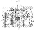
- Fig. 3 is a sectional view showing the state that a metal material is pushed into a die to extrude a helical internal gear.
- a helical internal gear extruding die unit generally designated at reference numeral 1 comprises a container 2, a die 3 and a mandrel 4. At the center of the container 2, there is defined a material insertion bore 2a which is vertically penetrating through the container and serves to restrain the outer periphery of a metal material 5.
- the die 3 is to form the outer periphery of the metal material 5 by pushing it into the die 3, and is rotatably fitted in an attachment hole 9a of a support plate 9 vertically movably supported to a plurality of upstanding guide rods 8 which are in turn attached to a stationary base 7 such as a bolster.
- the container 2 is placed over the upper surface of the die 3 with their axes aligned exactly.
- the container 2 and the die 3 have formed in their outer circumferences respective flanges 2b, 3a at which they are supported on the support plate 9 by a ring-like holder 11, fixed to the support plate 9 by means of bolts 10, for being circumferentially rotatable relative to each other.
- the support plate 9 is normally urged upward by compression springs 12 each disposed between the support plate 9 and the stationary base 7 around the guide rod 8 in concentric relation.
- the mandrel 4 consists of an upper mandrel 13 which is positioned inside the material insertion bore 2a of the container 2 for guiding the metal material 5 when its central bore 5a is fitted over the upper mandrel 13, and a lower mandrel 16 which is disposed contiguously below and coupled to the upper mandrel 13 through a joint sleeve 14 and a bolt 15 with their axes aligned exactly such that the upper and lower mandrels are rotatable relative to each other.
- the lower mandrel 16 has defined on its outer circumference a teeth section 161 with a desired helix angle for molding helix teeth of the helical internal gear. As shown in Fig.
- the teeth section 161 comprises an approach area (teeth deformation process area) 161a expanding linearly radially outward from the outer peripheral surface of the lower mandrel 16 as it goes ahead in the extruding direction of the metal material 5 (i.e., the direction of arrow X in Figs. 1 and 3), and a product configuration area 161b extending downward continuously from the lower end of the approach area 161a to form the complete shape of helical gear teeth.
- approach area titanium deformation process area
- 161a expanding linearly radially outward from the outer peripheral surface of the lower mandrel 16 as it goes ahead in the extruding direction of the metal material 5 (i.e., the direction of arrow X in Figs. 1 and 3)
- a product configuration area 161b extending downward continuously from the lower end of the approach area 161a to form the complete shape of helical gear teeth.
- each tooth has such sectional configurations at respective positions 1 - 4 that a tooth groove width d is gradually reduced in accordance with the involute curve of the molded tooth as it proceeds from the start end of the approach area 161a toward 161b, as indicated by 1 - 4 in Fig. 4.
- This increases flextural rigidity of the start end portion of the approach area 161a (i.e., the portion corresponding to 2 ) from which the metal material 5 starts to undergo flow deformation along the approach area 161a, and also enables smooth transition process of the metal material 5 to the helical internal gear teeth through flow deformation.
- an inwardly contracted portion 31 which causes the outer peripheral portion of the metal material 5 to be subjected to flow deformation gradually in the contracting direction, and which is located to face the start end of the approach area 161a of the lower mandrel 16.
- the inner peripheral surface of the die 3 has also a material outer periphery expanding portion 32 which is radially outwardly inclined from the top corresponding to the minimum inner diameter of the inwardly contracted portion 31 toward the extruding direction of the material (i.e., the direction of arrow X).
- the material outer periphery expanding portion 32 is located to face the approach area 161a of the lower mandrel 16 in complementary inclining relation thereto, and serves to restrain the outer periphery of the metal material 5 while allowing it to expand outward in response to effective expansion of the inner diameter of the metal material 5 during the process in which the inner peripheral portion of the metal material 5 is subjected to flow deformation gradually from the circular cross-section to the helical internal gear teeth by virtue of the approach area 161a of the lower mandrel 16.
- Designated at 33 is a material outer periphery forming portion located to face the product configuration area 161b.
- a cylindrical punch supported to the underside of a slider 18 by a holder 19.
- the punch 17 is to push the metal material 5 into a gap between the mandrel 4 and the container 2 as well as the die 3, and is supported in such an arrangement as making it rotatable circumferentially relative to the slider 18.
- the hollow metal material 5 with predetermined thickness and outer diameter is inserted into the bore 2a of the container 2, and the slider 18 is operated to descent in the direction of arrow A with the central bore 5a of the metal material 5 fitted over the upper mandrel 13.
- the support plate 9 is wholly descended against the compression springs 12, along with the container 2, the die 3 and the mandrel 4.
- the lower end surfaces of both the die 3 and the lower mandrel 16 strike against the upper surface of a receiver stand 20 fixedly mounted on the stationary base 7, the downward movement of the container 2, the die 3 and the mandrel 4 is stopped.
- the metal material 5′ is contracted by the presence of the inwardly contracted portion 31 of the die 3 for being defined to the sectional area necessary to mold the helical internal gear. Then, the inner peripheral portion of the metal material at its lower end enters the approach area 161a of the teeth section 161 of the lower mandrel 16 for molding the helix teeth, whereupon the helix teeth start to be molded on the metal material 5′.
- the material deformation as experienced in the inner peripheral portion of the metal material 5′ at this time corresponds to the sectional configuration of the approach area 161a as indicated by 2 in Fig. 2.
- the punch 17 Upon completion of full-stroke pushing of the first metal material 5′ by the punch 17, the punch 17 is raised up and a next metal material 5 is inserted into the container 2, as shown in Fig. 1, followed by moving the punch 17 again downward to push the next metal material 5 into the container 2. Thereafter, by successively pushing subsequent metal materials 5 into the container 2 by the punch 17 in a like manner, the metal materials 5 are moved through the gap between the die 3 and the mandrel 4 one by one in the direction of arrow X. During passage through the gap between the die 3 and the mandrel 4, each metal material 5 is plastically formed into a helical internal gear having helix teeth on the inner circumference thereof.
- the inner peripheral portion of the metal material 5 is subjected to flow deformation gradually from the circular cross-section to the complete shape of helix teeth.
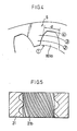
- the metal material is molded into a helical in ternal gear 21 which has perfect helix teeth 21a formed in its inner peripheral portion, and has its outer periphery 21b formed into the predetermined diameter by the material outer periphery expanding portion 32, as shown in Fig. 5.
- the helical internal gear 21 is dropped into the receiver stand 20.
- the flow material caused by effective expansion of the inner diameter of the metal material 5 during the above process of teeth deformation is absorbed by the presence of the material outer periphery expanding portion 32 which is inclined expansively in complementary relation to the approach area 161a, so that the metal material 5 is prevented from undergoing flow extension in the axial direction of the mandrel 4.
- Fig. 6 is a set of explanatory views showing the fact that the sectional areas at respective horizontal planes of the metal material are kept constant throughout the molding process of the helical internal gear in the die unit.
- Fig. 6(A) shows a section of the metal material 5 at the horizontal plane taken along the line VIA - VIA in Fig. 3
- Fig. 6(B) shows a section of the metal material 5 under molding at the horizontal plane taken along the line VIB - VIB in Fig. 3
- Fig. 6(C) shows a section of the final product at the horizontal plane taken along the line VIC - VIC in Fig. 3.
- the material extension in the axial direction of the metal material 5 is prevented, and there occurs no gap between the lead of the incomplete teeth shape formed in the inner circumference of the material and the lead of the lower mandrel teeth section held in contact with the former, even in the transition process from the approach area 161a of the lower mandrel 16 to the product configuration area 161b for molding the complete teeth shape. Also, there occurs no lead error in the direction of advancement between the teeth section molded in the inner circumference of the material and the corresponding teeth section of the lower mandrel 4, whereby the perfect helix teeth are formed in the inner circumference of the material.
- the metal material has to rotate by overcoming the frictional resistance between the container 2 as well as the upper mandrel 13 and the metal material, if the die 3 and the upper mandrel 13 are integral with the container 2 and the lower mandrel 16, respectively, or if the relative rotational movement is restricted between the die 3 and the container 2 and between the upper and lower mandrels 13, 16.
- a portion of the metal material 5 just enters the approach area 161a of the lower mandrel 16, and hence rotation of the metal material 5 produces extreme stress in the approach area 161a.
- the metal material 5 would be deformed unnecessarily, or the teeth section 161 of the lower mandrel would be damaged.
- the approach area 161a in the teeth section 161 of the lower mandrel 16 for molding the helix teeth is designed to have an inclined sectional shape with an upward slope in the extruding direction of the metal material, as indicated by 1 - 4 in Fig. 4, it is possible to high-accurately form the helix teeth on the material without imposing undue forces and to simplify the molding process, with the result that rigidity of the teeth section 161 can be increased and the service life of the die unit can be improved.
- Fig. 7 is a sectional view showing the entire construction of an apparatus for plastically extruding helical gears according to the present invention
- Fig. 8 is an enlarged sectional view of an essential part of the apparatus
- Fig. 9 is a sectional view showing the state that a metal material is pushed into a die to extrude a helical gear.
- a helical gear extruding die unit generally designated at reference numeral 101 comprises a container 102, a die 103 and a mandrel 104.
- a material insertion bore 102a which is vertically penetrating through the container and serves to restrain the outer contour of a metal material 105.
- the die 103 is to form helix teeth on the outer periphery of the metal material 105 by pushing it into the die 103, and is rotatably fitted in an attachment hole 109a of a support plate 109 vertically movably supported to a plurality of upstanding guide rods 108 which are in turn attached to a stationary base 107 such as a bolster.
- the container 102 is placed over the upper surface of the die 103 with their axes aligned exactly.
- the container 102 and the die 103 have formed in their outer circumferences respective flanges 102b, 103a at which they are supported on the support plate 109 by a ring-like holder 111, fixed to the support plate 9 by means of bolts 110, for being circumferentially rotatable relative to each other.
- the support plate 109 is normally urged upward by compression springs 112 each disposed between the support plate 109 and the stationary base 107 around the guide rod 108 in concentric relation.
- the die 103 has a cylindrical bore 131 with the diameter slightly larger than the material insertion bore 102a of the container 102, and a teeth section 132 with a desired helix angle is defined on an inner wall of the cylindrical bore 131 for molding helix teeth of the helical gear.
- the teeth section 132 comprises an approach area (teeth deformation process area) 132a expanding linearly radially from the inner surface of the cylindrical bore 131 toward the center as it goes ahead in the extruding direction of the metal material 105 (i.e., the direction of arrow Y in Fig.
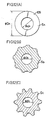
- each tooth has such sectional configurations at respective positions 1 - 6 that a tooth groove width d is gradually reduced in accordance with the involute curve of the molded tooth as it proceeds from inner surface of the cylindrical bore 131 toward the center, as indicated by 1 - 6 in Fig. 10.
- the mandrel 104 is disposed in alignment with the axes of the material insertion bore 102a of the container 102 and the cylindrical bore 131 of the die 103, and comprises a column portion 141 located inside the material insertion bore 102a of the container 102 for guiding the metal material 105 when its central bore 105a is fitted over the column portion 141, an outwardly expanded portion 143 which is continuously extended from the lower and of the column portion 141 through a tapered portion 142 and located inside the cylindrical bore 131 of the die 103 for defining the sectional area of the metal material 105 necessary to mold the helical gear, a material inner periphery forming portion 144 which is continuously extended from the lower end of the outwardly expanding portion 143 in facing relation to the approach area 132a in the teeth section of the die 103, and serves to restrain the inner periphery of the metal material 105 while allowing it to contract inward in response to effective contraction of the outer diameter of the metal material 105 during the process
- Designated at 113 in Figs. 7 and 9 is a cylindrical punch supported to the underside of a slider 114 by a holder 115.
- the punch 113 is to push the metal material 105 into a gap between the mandrel 104 and the container 102 as well as the die 103, and is supported in such an arrangement as making it rotatable circumferentially relative to the slider 114.
- the hollow metal material 105 with predetermined thickness and outer diameter is inserted into the bore 102a of the container 102, and the slider 114 is operated to descend in the direction of arrow B with the central bore 105a of the metal material 105 fitted over the column portion 141 of the mandrel 104.
- the punch 113 is thereby engaged with the upper end of the metal material 105 and then further moved downward, the support plate 109 is wholly descended against the compression springs 112, along with the container 102, the die 103 and the mandrel 104.
- the metal material 105′ is expanded by the presence of the outwardly expanded area 143 of the mandrel 104 for being defined to the sectional area necessary to mold the helical gear. Then, the outer peripheral portion of the metal material at its lower end enters the approach area 132a of the teeth section 132 of the die 103 for molding the helix teeth, whereupon the helix teeth start to be molded on the metal material 105′.
- the material deformation as experienced in the outer peripheral portion of the metal material 105′ at this time corresponds to the sectional configuration of the approach area 132a as indicated by 2 in Fig. 8.
- the punch 113 Upon completion of full-stroke pushing of the first metal material 105′ by the punch 113, the punch 113 is raised up and a next metal material 105 is inserted into the container 102, as shown in Fig. 7, followed by moving the punch 113 again downward to push the next metal material 105 into the container 102. Thereafter, by successively pushing subsequent metal materials 105 into the container 102 by the punch 113 in a like manner, the metal materials 105 are moved through the gap between the die 103 and the mandrel 104 one by one in the direction of arrow Y. During passage through the gap between the die 103 and the mandrel 104, each metal material 105 is plastically formed into a helical gear having helix teeth on the outer circumference thereof.
- the metal material 105 passes the approach area 132a of the die 103, the outer peripheral portion of the metal material 105 is subjected to flow deformation gradually from the circular cross-section to the complete shape of helix teeth.
- the metal material is molded into a helical gear 117 which has perfect helix teeth 117a formed in its outer peripheral portion, and has its inner periphery 117b formed into the predetermined diameter by the material inner periphery forming portion 144, as shown in Fig. 11.
- the helical gear 117 is dropped into the receiver stand 116.
- the flow material caused by effective contraction of the outer diameter of the metal material 105a during the above process of teeth deformation is absorbed by the presence of the material inner periphery forming portion 144 which is inclined contractedly in complementary relation to the approach area 132a, so that the metal material 105 is prevented from undergoing flow extension in the axial direction of the mandrel 104.
- Fig. 12 is a set of explanatory views showing the fact that the sectional areas at respective horizontal planes of the metal material are kept constant throughout the molding process of the helical gear in the die unit.
- Fig. 12(A) shows a section of the metal material 105 at the horizontal plane taken along the line XIIA - XIIA in Fig. 9
- Fig. 12(B) shows a section of the metal material 105 under molding at the horizontal plane taken along the line XIIB - XIIB in Fig. 9,
- Fig. 12(C) shows a section of the final product at the horizontal plane taken along the line XIIC - XIIC in Fig. 9.
- the material extension in the axial direction of the metal material 105 is prevented, and there occurs no gap between the lead of the incomplete teeth shape formed in the outer circumference of the material and the lead of the die teeth section held in contact with the former, even in the transition process from the approach area 132a of the die 103 to the product configuration area 132b for molding the complete teeth shape. Also, there occurs no lead error in the direction of advancement between the teeth section molded in the outer circumference of the material and the corresponding teeth section of the die 103, whereby the perfect helix teeth are formed in the outer circumference of the material.
- the metal material has to rotate by overcoming the frictional resistance between the container 102 and the metal material, if the die 103 is integral with the container 102, or if the relative rotational movement is restricted between the die 103 and the container 102.
- a portion of the metal material 105 just enters the approach area 132a of the die 103, and hence rotation of the metal material 105 produces extreme stress in the approach area 132a.
- the metal material 105 would be deformed unnecessarily, or the teeth section 132 of the die 103 would be damaged.
- the helical gear can be formed plastically with a high degree of accuracy.
- the approach area 132a in the teeth section 132 of the die 103 for molding the helix teeth is designed to have an inclined sectional shape with an upward slope in the extruding direction of the metal material, as indicated by 1 - 6 in Fig. 10, it is pos sible to high-accurately form the helix teeth on the material without imposing undue forces and to simplify the molding process, with the result that rigidity of the teeth section 132 can be increased and the service life of the die unit can be improved.
Landscapes
- Engineering & Computer Science (AREA)
- Mechanical Engineering (AREA)
- Forging (AREA)
- Gears, Cams (AREA)
Applications Claiming Priority (2)
| Application Number | Priority Date | Filing Date | Title |
|---|---|---|---|
| JP330926/87 | 1987-12-26 | ||
| JP62330926A JPH01170544A (ja) | 1987-12-26 | 1987-12-26 | ヘリカルインターナルギアの塑性加工装置 |
Publications (3)
| Publication Number | Publication Date |
|---|---|
| EP0322770A2 true EP0322770A2 (fr) | 1989-07-05 |
| EP0322770A3 EP0322770A3 (en) | 1990-09-05 |
| EP0322770B1 EP0322770B1 (fr) | 1993-09-29 |
Family
ID=18237995
Family Applications (1)
| Application Number | Title | Priority Date | Filing Date |
|---|---|---|---|
| EP88121517A Expired - Lifetime EP0322770B1 (fr) | 1987-12-26 | 1988-12-22 | Procédé et appareil pour le formage de roues à denture intérieure hélicoidale et de roues à denture hélicoidale |
Country Status (6)
| Country | Link |
|---|---|
| US (1) | US4924690A (fr) |
| EP (1) | EP0322770B1 (fr) |
| JP (1) | JPH01170544A (fr) |
| KR (1) | KR930001088B1 (fr) |
| AU (1) | AU607297B2 (fr) |
| DE (1) | DE3884590T2 (fr) |
Cited By (6)
| Publication number | Priority date | Publication date | Assignee | Title |
|---|---|---|---|---|
| DE4411410A1 (de) * | 1993-08-31 | 1995-03-02 | Ntn Toyo Bearing Co Ltd | Kaltformverfahren für Zahnringprodukte und Gerät zum Ausformen derselben |
| US5764051A (en) * | 1993-08-31 | 1998-06-09 | Ntn Corporation | Cold forged toothed ring for producing rotational speed signals |
| EP1005932A3 (fr) * | 1998-11-13 | 2001-08-29 | SMS Eumuco GmbH | Procédé et dispositif pour la formation plastique d'un cylindre creux à denture intérieure |
| WO2003080271A1 (fr) * | 2002-03-26 | 2003-10-02 | New Form Tec Gmbh | Procede de production d'une piece annulaire dotee d'une denture interne, notamment d'un baladeur, et dispositif correspondant |
| CN109420733A (zh) * | 2017-08-28 | 2019-03-05 | 丰田自动车株式会社 | 齿轮的锻造成形方法及齿轮的锻造成形装置 |
| CN111112541A (zh) * | 2018-10-31 | 2020-05-08 | 丰田自动车株式会社 | 用于锻造齿轮的方法和设备 |
Families Citing this family (18)
| Publication number | Priority date | Publication date | Assignee | Title |
|---|---|---|---|---|
| JPH0651987U (ja) * | 1992-12-18 | 1994-07-15 | 松下冷機株式会社 | 自動販売機の商品収容棚 |
| US5551270A (en) * | 1994-07-18 | 1996-09-03 | Ford Motor Company | Extrusion forming of internal helical splines |
| SE9503474L (sv) * | 1995-10-06 | 1996-12-23 | Mark Lars Jansson | Förfarande för kontinuerlig framställning av profiler och anordning för genomförande av förfarandet |
| JP2763762B2 (ja) * | 1996-04-12 | 1998-06-11 | 三菱製鋼株式会社 | 内径スプラインシャフトの成形方法 |
| US5732586A (en) * | 1996-09-19 | 1998-03-31 | Ford Global Technologies, Inc. | Cold extrusion for helical gear teeth |
| JP3160619B2 (ja) * | 1997-05-23 | 2001-04-25 | 大蔵省造幣局長 | ヘリカルギザを有するメダルまたは貨幣の製造方法および装置 |
| JP3414215B2 (ja) * | 1997-08-28 | 2003-06-09 | 住友電気工業株式会社 | 曲り歯傘歯車の成形方法及び粉末成形装置 |
| US5996229A (en) * | 1998-09-25 | 1999-12-07 | Yang; Tsung-Hsun | Method and mold die for forming a spiral bevel gear from metal powders |
| KR20010102623A (ko) * | 2000-05-02 | 2001-11-16 | 배 장 | 헬리컬 기어의 성형장치 |
| US6592809B1 (en) | 2000-10-03 | 2003-07-15 | Keystone Investment Corporation | Method for forming powder metal gears |
| US6981324B2 (en) | 2003-03-26 | 2006-01-03 | American Axle & Manufacturing, Inc. | Method of manufacturing net-shaped gears for a differential assembly |
| US7025929B2 (en) * | 2004-04-08 | 2006-04-11 | Pmg Ohio Corp. | Method and apparatus for densifying powder metal gears |
| AT504081B1 (de) * | 2006-09-04 | 2008-11-15 | Miba Sinter Austria Gmbh | Verfahren zur oberflächenverdichtung eines sinterteils |
| US8215880B2 (en) * | 2008-10-03 | 2012-07-10 | Ford Global Technologies, Llc | Servo motor for actuating a mandrel while extruding helical teeth |
| JP4940255B2 (ja) * | 2009-03-02 | 2012-05-30 | 株式会社ヤマナカゴーキン | ヘリカル内歯ギヤの加工方法及び金型 |
| JP5609291B2 (ja) * | 2010-06-15 | 2014-10-22 | 大同特殊鋼株式会社 | 内歯ギア製造用マンドレルおよびそのマンドレルを使用した内歯ギア製造方法と製造装置 |
| JP5742527B2 (ja) * | 2011-07-13 | 2015-07-01 | 大同特殊鋼株式会社 | 内歯ヘリカルギア製造用マンドレル、内歯ヘリカルギア製造装置、及び、内歯ヘリカルギアの製造方法 |
| US11707786B2 (en) * | 2020-04-17 | 2023-07-25 | PMG Indiana LLC | Apparatus and method for internal surface densification of powder metal articles |
Family Cites Families (9)
| Publication number | Priority date | Publication date | Assignee | Title |
|---|---|---|---|---|
| US2767438A (en) * | 1952-04-14 | 1956-10-23 | Borg Warner | Method and apparatus for making torque-transmitting elements |
| US3564894A (en) * | 1968-08-30 | 1971-02-23 | Wilfred J Sharon | Apparatus and method of forming tubular articles |
| US3605475A (en) * | 1969-06-19 | 1971-09-20 | Nat Machinery Co The | Method and apparatus for extruding gear blanks |
| US3828628A (en) * | 1970-11-24 | 1974-08-13 | Peugeot & Renault | Methods of extruding helical gear blanks |
| JPS57175043A (en) * | 1981-04-22 | 1982-10-27 | Hitachi Ltd | Inside diameter shape working method of cylindrical parts |
| US4509353A (en) * | 1982-03-23 | 1985-04-09 | Nissan Motor Company, Limited | Method of and apparatus for forming gears |
| JPS6061131A (ja) * | 1983-09-13 | 1985-04-08 | Hitachi Ltd | 金属製品の塑性加工方法 |
| GB2197605B (en) * | 1986-12-30 | 1990-06-20 | Honda Motor Co Ltd | Forming cup-shaped products having internal gears |
| US4785648A (en) * | 1987-03-23 | 1988-11-22 | Allied Products Corporation | Method and apparatus for embossing the inside surface of a cup-shaped article |
-
1987
- 1987-12-26 JP JP62330926A patent/JPH01170544A/ja active Granted
-
1988
- 1988-12-20 US US07/287,396 patent/US4924690A/en not_active Expired - Fee Related
- 1988-12-22 AU AU27432/88A patent/AU607297B2/en not_active Ceased
- 1988-12-22 EP EP88121517A patent/EP0322770B1/fr not_active Expired - Lifetime
- 1988-12-22 DE DE88121517T patent/DE3884590T2/de not_active Expired - Fee Related
- 1988-12-26 KR KR1019880017508A patent/KR930001088B1/ko not_active Expired - Fee Related
Cited By (12)
| Publication number | Priority date | Publication date | Assignee | Title |
|---|---|---|---|---|
| DE4411410A1 (de) * | 1993-08-31 | 1995-03-02 | Ntn Toyo Bearing Co Ltd | Kaltformverfahren für Zahnringprodukte und Gerät zum Ausformen derselben |
| GB2281527A (en) * | 1993-08-31 | 1995-03-08 | Ntn Toyo Bearing Co Ltd | Cold forming method and apparatus |
| US5544548A (en) * | 1993-08-31 | 1996-08-13 | Ntn Corporation | Cold forming method of toothed ring-shaped products and forming apparatus for its use |
| GB2281527B (en) * | 1993-08-31 | 1997-12-10 | Ntn Toyo Bearing Co Ltd | Cold forming method |
| US5764051A (en) * | 1993-08-31 | 1998-06-09 | Ntn Corporation | Cold forged toothed ring for producing rotational speed signals |
| DE4411410B4 (de) * | 1993-08-31 | 2005-12-29 | Ntn Corp. | Kaltformverfahren und Formwerkzeug für Zahnringprodukte |
| EP1005932A3 (fr) * | 1998-11-13 | 2001-08-29 | SMS Eumuco GmbH | Procédé et dispositif pour la formation plastique d'un cylindre creux à denture intérieure |
| WO2003080271A1 (fr) * | 2002-03-26 | 2003-10-02 | New Form Tec Gmbh | Procede de production d'une piece annulaire dotee d'une denture interne, notamment d'un baladeur, et dispositif correspondant |
| US7168281B2 (en) | 2002-03-26 | 2007-01-30 | Neumayer Tekfor Gmbh | Method for producing an annular element comprising an inner toothing, especially a sliding sleeve, and device for carrying out the method |
| CN109420733A (zh) * | 2017-08-28 | 2019-03-05 | 丰田自动车株式会社 | 齿轮的锻造成形方法及齿轮的锻造成形装置 |
| EP3450045A1 (fr) * | 2017-08-28 | 2019-03-06 | Toyota Jidosha Kabushiki Kaisha | Procédé et appareil pour forger des engrenages |
| CN111112541A (zh) * | 2018-10-31 | 2020-05-08 | 丰田自动车株式会社 | 用于锻造齿轮的方法和设备 |
Also Published As
| Publication number | Publication date |
|---|---|
| US4924690A (en) | 1990-05-15 |
| DE3884590D1 (de) | 1993-11-04 |
| DE3884590T2 (de) | 1994-02-03 |
| KR890009494A (ko) | 1989-08-02 |
| JPH01170544A (ja) | 1989-07-05 |
| EP0322770A3 (en) | 1990-09-05 |
| JPH0525578B2 (fr) | 1993-04-13 |
| AU2743288A (en) | 1989-06-29 |
| KR930001088B1 (ko) | 1993-02-15 |
| EP0322770B1 (fr) | 1993-09-29 |
| AU607297B2 (en) | 1991-02-28 |
Similar Documents
| Publication | Publication Date | Title |
|---|---|---|
| EP0322770A2 (fr) | Procédé et appareil pour le formage de roues à denture intérieure hélicoidale et de roues à denture hélicoidale | |
| KR101153083B1 (ko) | 휠의 제조 방법과 그 휠 | |
| US8061174B2 (en) | Preventing voids in extruded teeth or splines | |
| EP0572105B1 (fr) | Procédé et dispositif pour former une crémaillères tubulaire | |
| WO1995014568A1 (fr) | Matrice double a mise en phase | |
| US5544548A (en) | Cold forming method of toothed ring-shaped products and forming apparatus for its use | |
| US4878370A (en) | Cold extrusion process for internal helical gear teeth | |
| US4509353A (en) | Method of and apparatus for forming gears | |
| US5732586A (en) | Cold extrusion for helical gear teeth | |
| CN109047361A (zh) | 侧向挤压成型模具、带非直通内凹齿形的成型装置及方法 | |
| JP2613529B2 (ja) | アンダーカット部を有する粉末成形品の製造方法および装置 | |
| JPH0331537B2 (fr) | ||
| JPH11147158A (ja) | 内外ギア同時成形方法とこれに用いる成形装置 | |
| CN1049373C (zh) | 金属板制旋转构件的制造方法 | |
| JP4665879B2 (ja) | 歯車鍛造装置及び歯車鍛造方法 | |
| US5396789A (en) | Procedure for manufacturing corrugated tubes | |
| JPH01150427A (ja) | ヘリカルリングギヤの製造装置 | |
| CN221983536U (zh) | 一种齿轨轮挤压模具 | |
| CN113305264B (zh) | 链条滚子的腰鼓成型工艺及成型模具 | |
| JP2890917B2 (ja) | フランジ付歯車の製造方法 | |
| JP2861424B2 (ja) | 内歯車製造装置 | |
| JPH0230350A (ja) | 回転鍛造装置 | |
| JP2893977B2 (ja) | 歯車の押出成形装置 | |
| JPH10230396A (ja) | はすば歯車の粉末成形装置 | |
| CN120506421B (zh) | 一种活节螺栓及其生产设备、生产工艺 |
Legal Events
| Date | Code | Title | Description |
|---|---|---|---|
| PUAI | Public reference made under article 153(3) epc to a published international application that has entered the european phase |
Free format text: ORIGINAL CODE: 0009012 |
|
| AK | Designated contracting states |
Kind code of ref document: A2 Designated state(s): DE FR GB IT SE |
|
| PUAL | Search report despatched |
Free format text: ORIGINAL CODE: 0009013 |
|
| AK | Designated contracting states |
Kind code of ref document: A3 Designated state(s): DE FR GB IT SE |
|
| 17P | Request for examination filed |
Effective date: 19900926 |
|
| 17Q | First examination report despatched |
Effective date: 19920316 |
|
| GRAA | (expected) grant |
Free format text: ORIGINAL CODE: 0009210 |
|
| ITF | It: translation for a ep patent filed | ||
| AK | Designated contracting states |
Kind code of ref document: B1 Designated state(s): DE FR GB IT SE |
|
| REF | Corresponds to: |
Ref document number: 3884590 Country of ref document: DE Date of ref document: 19931104 |
|
| ET | Fr: translation filed | ||
| PLBE | No opposition filed within time limit |
Free format text: ORIGINAL CODE: 0009261 |
|
| STAA | Information on the status of an ep patent application or granted ep patent |
Free format text: STATUS: NO OPPOSITION FILED WITHIN TIME LIMIT |
|
| 26N | No opposition filed | ||
| EAL | Se: european patent in force in sweden |
Ref document number: 88121517.2 |
|
| REG | Reference to a national code |
Ref country code: GB Ref legal event code: 746 Effective date: 19961106 |
|
| PGFP | Annual fee paid to national office [announced via postgrant information from national office to epo] |
Ref country code: FR Payment date: 19990929 Year of fee payment: 12 |
|
| PGFP | Annual fee paid to national office [announced via postgrant information from national office to epo] |
Ref country code: SE Payment date: 19991005 Year of fee payment: 12 |
|
| PGFP | Annual fee paid to national office [announced via postgrant information from national office to epo] |
Ref country code: GB Payment date: 19991111 Year of fee payment: 12 |
|
| PGFP | Annual fee paid to national office [announced via postgrant information from national office to epo] |
Ref country code: DE Payment date: 20000223 Year of fee payment: 12 |
|
| PG25 | Lapsed in a contracting state [announced via postgrant information from national office to epo] |
Ref country code: GB Free format text: LAPSE BECAUSE OF NON-PAYMENT OF DUE FEES Effective date: 20001222 |
|
| PG25 | Lapsed in a contracting state [announced via postgrant information from national office to epo] |
Ref country code: SE Free format text: LAPSE BECAUSE OF NON-PAYMENT OF DUE FEES Effective date: 20001223 |
|
| EUG | Se: european patent has lapsed |
Ref document number: 88121517.2 |
|
| GBPC | Gb: european patent ceased through non-payment of renewal fee |
Effective date: 20001222 |
|
| PG25 | Lapsed in a contracting state [announced via postgrant information from national office to epo] |
Ref country code: FR Free format text: LAPSE BECAUSE OF NON-PAYMENT OF DUE FEES Effective date: 20010831 |
|
| REG | Reference to a national code |
Ref country code: FR Ref legal event code: ST |
|
| PG25 | Lapsed in a contracting state [announced via postgrant information from national office to epo] |
Ref country code: DE Free format text: LAPSE BECAUSE OF NON-PAYMENT OF DUE FEES Effective date: 20011002 |
|
| PG25 | Lapsed in a contracting state [announced via postgrant information from national office to epo] |
Ref country code: IT Free format text: LAPSE BECAUSE OF NON-PAYMENT OF DUE FEES;WARNING: LAPSES OF ITALIAN PATENTS WITH EFFECTIVE DATE BEFORE 2007 MAY HAVE OCCURRED AT ANY TIME BEFORE 2007. THE CORRECT EFFECTIVE DATE MAY BE DIFFERENT FROM THE ONE RECORDED. Effective date: 20051222 |