EP0322836A2 - Méthode d'installation d'un pétrin dans un four et dispositif pour la mise en oeuvre de cette méthode - Google Patents
Méthode d'installation d'un pétrin dans un four et dispositif pour la mise en oeuvre de cette méthode Download PDFInfo
- Publication number
- EP0322836A2 EP0322836A2 EP88121672A EP88121672A EP0322836A2 EP 0322836 A2 EP0322836 A2 EP 0322836A2 EP 88121672 A EP88121672 A EP 88121672A EP 88121672 A EP88121672 A EP 88121672A EP 0322836 A2 EP0322836 A2 EP 0322836A2
- Authority
- EP
- European Patent Office
- Prior art keywords
- kneading
- heating chamber
- heating
- trough
- kneading trough
- Prior art date
- Legal status (The legal status is an assumption and is not a legal conclusion. Google has not performed a legal analysis and makes no representation as to the accuracy of the status listed.)
- Granted
Links
Images


Classifications
-
- A—HUMAN NECESSITIES
- A47—FURNITURE; DOMESTIC ARTICLES OR APPLIANCES; COFFEE MILLS; SPICE MILLS; SUCTION CLEANERS IN GENERAL
- A47J—KITCHEN EQUIPMENT; COFFEE MILLS; SPICE MILLS; APPARATUS FOR MAKING BEVERAGES
- A47J37/00—Baking; Roasting; Grilling; Frying
-
- A—HUMAN NECESSITIES
- A21—BAKING; EDIBLE DOUGHS
- A21C—MACHINES OR EQUIPMENT FOR MAKING OR PROCESSING DOUGHS; HANDLING BAKED ARTICLES MADE FROM DOUGH
- A21C1/00—Mixing or kneading machines for the preparation of dough
- A21C1/02—Mixing or kneading machines for the preparation of dough with vertically-mounted tools; Machines for whipping or beating
-
- A—HUMAN NECESSITIES
- A21—BAKING; EDIBLE DOUGHS
- A21B—BAKERS' OVENS; MACHINES OR EQUIPMENT FOR BAKING
- A21B7/00—Baking plants
- A21B7/005—Baking plants in combination with mixing or kneading devices
-
- B—PERFORMING OPERATIONS; TRANSPORTING
- B01—PHYSICAL OR CHEMICAL PROCESSES OR APPARATUS IN GENERAL
- B01F—MIXING, e.g. DISSOLVING, EMULSIFYING OR DISPERSING
- B01F35/00—Accessories for mixers; Auxiliary operations or auxiliary devices; Parts or details of general application
- B01F35/90—Heating or cooling systems
- B01F2035/99—Heating
-
- B—PERFORMING OPERATIONS; TRANSPORTING
- B01—PHYSICAL OR CHEMICAL PROCESSES OR APPARATUS IN GENERAL
- B01F—MIXING, e.g. DISSOLVING, EMULSIFYING OR DISPERSING
- B01F27/00—Mixers with rotary stirring devices in fixed receptacles; Kneaders
- B01F27/80—Mixers with rotary stirring devices in fixed receptacles; Kneaders with stirrers rotating about a substantially vertical axis
-
- B—PERFORMING OPERATIONS; TRANSPORTING
- B01—PHYSICAL OR CHEMICAL PROCESSES OR APPARATUS IN GENERAL
- B01F—MIXING, e.g. DISSOLVING, EMULSIFYING OR DISPERSING
- B01F35/00—Accessories for mixers; Auxiliary operations or auxiliary devices; Parts or details of general application
- B01F35/30—Driving arrangements; Transmissions; Couplings; Brakes
- B01F35/32—Driving arrangements
- B01F35/321—Disposition of the drive
- B01F35/3213—Disposition of the drive at the lower side of the axis, e.g. driving the stirrer from the bottom of a receptacle
-
- Y—GENERAL TAGGING OF NEW TECHNOLOGICAL DEVELOPMENTS; GENERAL TAGGING OF CROSS-SECTIONAL TECHNOLOGIES SPANNING OVER SEVERAL SECTIONS OF THE IPC; TECHNICAL SUBJECTS COVERED BY FORMER USPC CROSS-REFERENCE ART COLLECTIONS [XRACs] AND DIGESTS
- Y10—TECHNICAL SUBJECTS COVERED BY FORMER USPC
- Y10T—TECHNICAL SUBJECTS COVERED BY FORMER US CLASSIFICATION
- Y10T29/00—Metal working
- Y10T29/49—Method of mechanical manufacture
- Y10T29/49826—Assembling or joining
-
- Y—GENERAL TAGGING OF NEW TECHNOLOGICAL DEVELOPMENTS; GENERAL TAGGING OF CROSS-SECTIONAL TECHNOLOGIES SPANNING OVER SEVERAL SECTIONS OF THE IPC; TECHNICAL SUBJECTS COVERED BY FORMER USPC CROSS-REFERENCE ART COLLECTIONS [XRACs] AND DIGESTS
- Y10—TECHNICAL SUBJECTS COVERED BY FORMER USPC
- Y10T—TECHNICAL SUBJECTS COVERED BY FORMER US CLASSIFICATION
- Y10T29/00—Metal working
- Y10T29/49—Method of mechanical manufacture
- Y10T29/49998—Work holding
Definitions
- the present invention generally relates to a heating and cooking apparatus having a kneading trough detachably accommodated therein, and more particularly, to an installation method and arrangement of the kneading trough in the heating and cooking apparatus.
- an oven has been used when an object or a food is cooked through roasting.
- a kneading device has been employed for the object to be cooked through kneading.
- an automatic bread baking apparatus has been brought into the market by which, for example, bread can be automatically made through consecutive operation from kneading to baking.
- an oven equipped with a kneading arrangement has been also in the market.
- the trough should be taken out of the oven, and the kneaded material should be changed into another trough or plate for fermentation and baking.
- the former automatic bread baking apparatus is exclusively used for bread. Therefore, in the case where a variety of breads such as rolls, croissants, etc. are desired, the appratus can serve only for a part of a series of the baking operation, namely, kneading and fermentation, with requiring an oven to be added which is large enough to bake several rolls or croissants, etc. at one time on a plate.
- the above-described cooking unit is able to be used in combination with an electronic oven range or a toaster range, realizing more highly concentrated cooking apparatus.
- the trough exclusive for kneading and baking operations has generally the capacity of 1-2 loaves of bread, which will be apparent from the fact that the automatic bread baking apparatus in the commercial market is rendered capable of baking 1-2 loaves of bread.
- the trough is put in or taken out of the center of the heating chamber of the electric oven, many problems are given rise to. In other words, the operation itself is troublesome, causing an erroneous operation which results in an accident or breakage of the oven, a burn of the user, etc.
- the kneading operation requires large rotating force with high speeds, it is necessary that the trough and the electric oven be completely secured to each other.
- a heating and cooking apparatus not limited to the above case, which can make rice-cakes, sourdoughs of cakes and cookies or can serve as a juicer or a mixer rotated at high speeds.
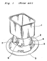
- Fig. 1 shows an example how a kneading trough is fixed to the heating and cooking apparatus in the conventional manner.
- the kneading trough 1 has a foot part 2, so that the trough 1 is mounted through the foot part 2 in a to-be-engaged portion 3 formed in a fitting part 5 at the bottom of a heating chamber.
- Several projections 4 are formed in the foot part 2. Accordingly, when the trough 1 is placed at the bottom of the heating chamber and rotated by predetermined angles, the projections 4 of the foot part 2 are come into secure engagement with the to-be-engaged portion 3 at the bottom of the heating chamber.
- the foot part 2 is formed circular, a lock member 6 is provided so as to prevent the trough 1 from slipping off the to-be-engaged portion 3 during rotation. The lock member 6 is come in position by vertical movement of a lever 7.
- both hands of the user are needed to install or detach the trough.
- a series of operations from kneading to baking is consecutively carried out, for example, when bread is baked, the trough should be taken out of the apparatus while the lever of the lock member is manipulated after the bread is completely baked.
- the trough is desired to be removed from the apparatus immediately after the completion of baking, it may be feared that a burn or an injury be possibly given to the user since the interior of the heating chamber becomes hot.
- the kneading trough is fixedly accommodated into the box-like heating chamber, therefore, into a limited space of the heating chamber.
- the trough is inserted into the interior of the heating chamber from a lateral window, and placed in the bottom of the heating chamber in such manner as to be pressed down into the bottom of the heating chamber, and then rotated for fixing.
- the oven may be operated even through the engagement between the trough and the main body of the oven is insufficient, causing an accident of the oven or taking a fire.
- the inside surface of the heating chamber is coated with points or undergoes the surface-treatment, the coated or the surface-treated surface may be damaged because of the friction during the engagement, resulting in unfavorable appearance.
- the to-be-engaged portion in the bottom of the heating chamber is formed by a sheet metal, the end surface of the sheet metal is exposed and accordingly becomes an obstacle to cleaning, resulting in residual moisture and dregs in the engaging portion. Hands may be cut when the stains or the food residues are removed. Accordingly, the installation method of the trough through rotation is disadvantageous from the viewpoints of operation convenience, cleanliness and safety.
- the conventional method for installing the kneading trough into the oven carries such fears as are resulted in a failure of cooking because of the rattling or disengagement of the trough during the operation as well as an accident or a fire of the oven.
- the user may be burnt or get injured, or receive an electric shock.
- an essential object of the present invention is to provide a heating and cooking apparatus which is so arranged that a kneading trough is easily installed in or taken out of a heating chamber.
- a second object of the present invention is to provide a heating and cooking apparatus of the type referred to above in which the kneading trough is easily and securely installed in or taken out of a heating chamber without rotating the trough.
- a third object of the present invention is to provide a heating and cooking apparatus of the type referred to above in which the kneading trough is so engaged with the heating chamber as to be easily installed in or taken out of the heating chamber while a large rotating force from a motor which is a driving source for kneading is securely transmitted to a kneading vane.
- a fourth object of the present invention is to provide a heating and cooking apparatus of the type referred to above in which the kneading trough and the heating chamber are secured to each other through projected portions thereof with the help of the adhesive suction force of the magnetic elements, instead of the friction force as a result of the rotation of the engaging portion, so that it becomes easy to install the kneading trough into the heating chamber and to clean the trough, without rattlings due to the friction during the rotation taking place.
- a fifth object of the present invention is to provide a heating and cooking apparatus of the type referred to above in which a handle is provided in the kneading trough at the lateral side of the trough, so that one can hold the kneading trough easily by one hand with safety.
- the kneading trough and the to-be-engaged portion at the bottom of the heating chamber are formed square to receive the force in the rotating direction of the trough by the corners, and accordingly the strength in the rotating direction is increased, so that the kneading trough is prevented from rattling or the trough is prevented from being disengaged from the apparatus during the operation. Therefore, the heating and cooking apparatus of the present invention is improved in operating safety. Because of the square shape of the kneading trough, the kneading trough can be easily positioned in the heating and cooking apparatus. The user can get rid of worrisome manipulations when the kneading trough is installed in or removed from the heating and cooking apparatus.
- the kneading trough is provided with a projected portion and also the to-be-engaged portion in the heating chamber is formed with a hole or a groove, and moreover both of the kneading trough and the to-be-engaged portion in the heating chamber are provided respectively with a magnetic element.
- the projected portion of the kneading trough and the to-be-engaged portion of the heating chamber can be vertically secured to each other because of the attraction force of the magnetic elements. Accordingly, the engaging portion is free from wear and tear, and the coating or surface-treatment of the engaging portion is never damaged. The user can enjoy a good looking of the apparatus at all times.
- a handle is provided in the kneading trough at the lateral side thereof, the user can install or detach the kneading trough by one hand, which is highly convenient in use and safe, without dangerous injury or burn being added when the user installs or removes the kneading trough.
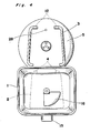
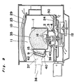
- an outer block 10 of the apparatus has a heating chamber 11 at the bottom of which is mounted a fitting part 5 formed of aluminum through die casting so as to fix a kneading trough 1.
- a to-be-engaged part 3 in a generally square shape in the fitting part 5.
- the to-be-engaged part 3 has a hole portion 12 in which a projected portion 4 of a foot 2 of the kneading trough 1 is inserted.
- a permanent magnet 13 built in the lower part of the fitting part 5 is securely adhered to a metal plate 14 which is made of a ferromagnetic material in a position corresponding to the permanent magnet 13 at the bottom of the foot part 2. It may be possible that the metal plate 14 is built in the lower part of the fitting part 5 and the permanent magnet 13 is provided in the foot 2 of the kneading trough 1.
- a handle 15 is provided in the lateral surface of the kneading trough 1, so that the kneading trough 1 can be easily installed in or removed from the heating and cooking apparatus, or carried out.
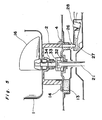
- a driving motor 17 transmits the rotating force, through a small pulley 18, a belt 19 and a large pulley 20, to a first rotary shaft 21.
- a prime rotary coupling member 32 is fixedly mounted in the first rotary shaft 21, which is meshed with a driven rotary coupling member 33 integrally formed with a second rotary shaft 34 of the kneading trough 1. Therefore, the rotating force transmitted to the first rotary shaft 21 is transmitted to the second rotary shaft 34, thereby rotating the kneading vane 16.
- the motor 17 is controlled by a control unit 22, so that the motor 17 is rotated in a a reversed direction or in an intermittent manner.
- the heating and cooking apparatus includes an upper heater 23 in the upper part of the heating chamber 11 and a lower heater 24 in the lower part of the heating chamber. Those heaters 23 and 24 are operated in the fermentation and baking operations, and the temperatures of the heaters 23 and 24 are also controlled by the control unit 22.
- the upper and lower heaters 23 and 24 are respectively covered with an upper insulative member 29 and a lower insulative member 30 for the purpose of improving the thermal efficiency.
- a magnetron 25 which is employed in the high frequency heating operation emits high frequency waves through an opening 31 formed in the lateral wall of the heating chamber into the heating chamber 11.
- the conventional locking mechanism 6 is not required, with no necessity for securing the kneading trough in pressed contact with the to-be-engaged portion.
- the kneading trough can be installed in or taken out of the heating chamber 11 with great ease.
- the force in the rotating direction is received by the corners, and accordingly the kneading trough 1 is prevented from rattling due to the wearing-out or slipping off the to-be-engaged portion 3.
- the projected portion 4 of the foot part 2 of the kneading rough 1 which is formed corresponding to the hole portion 12 is inserted into the hole portion 12 of the to-be-engaged portion 3 in the depth inside the heating chamber, with the help of the handle 15 mounted in the lateral side of the kneading trough 1.
- the to-be-engaged portion 3 serves also as a guide frame, so that the projected portion 4 of the kneading trough 1 can be easily inserted into the hole portion 12 as the kneading trough 1 is being slid.
- the permanent magnet 13 provided in the lower part of the fitting part 5 is securely adhered to the metal plate 14 made of a ferromagnetic material and provided at the bottom of the foot part 2 confronting to the permanent magnet 13, because of the magnetic force.
- the width of the to-be-engaged portion 3 at the side of the opening window of the heating chamber is made larger than that at the deep side of the heating chamber, and the foot part 2 of the kneading trough 1 is formed in the corresponding shape, there may be found sufficient room between the to-be-engaged portion 3 and the kneading trough 1 at the initial stage of the installation of the kneading trough 1.
- the to-be-engaged portion 3 serves as the guide frame, so that the room between the to-be-engaged portion 3 and the kneading trough 1 is gradually reduced as the kneading trough 1 is inserted along the guide frame while the kneading trough is being slid.
- the kneading trough 1 when the kneading trough 1 is completely installed, it can be fixedly secured to the to-be-engaged portion 3.
- the kneading trough can be installed even in the case of a box-shaped heating chamber by sliding the kneading trough from the front of the chamber. Accordingly, the installation arrangement of the prevent invention is convenient in use and free from such dangers as hurts or burns to the user.
- to-be-engaged portion 3 may be formed with a groove, not the hole portion, functioning in the same manner.
- the handle 15 is provided in the lateral wall of the kneading trough 1, it is greatly convenient that the user can hold the kneading trough with one hand. Moreover, since the handle is secured to the kneading trough at at least the opposite ends thereof, the kneading trough is consequently reinforced and becomes solid, resulting in improved durability.
- the to-be-engaged portion 3 is made of aluminum through die casting, and therefore the to-be-engaged portion 3 is ready to be formed into various other configurations. Also, the outer peripheral surface of the to-be-engaged portion 3 can be rendered smooth R. Accordingly, such fears as cutting of a finger, etc. will be avoided.
- the to-be-engaged portion 3 made through aluminum die casting is sufficiently strong, and the size of the engaging portion of the to-be-engaged portion 3 can be made as small as possible, assuring easiness for cleaning.
- the end surface of the to-be-engaged portion 3 may be subjected to R treatment or the like, and the foot part 2 of the kneading trough 1 may be formed into a polygonal shape such as a hexagonal shape, etc. to be strong.
- both the fitting part 5 and the to-be-engaged portion 3 may be formed by a sheet metal reducing work through stamping.
- the description hereinbelow is directed to a detection unit which is provided so as to detect the presence of the kneading trough thereby to prevent the imperfect engagement of the kneading trough.
- a detection pin 26 is pressed down.
- the depressed detection pin 26 adds to a detection lever 27 provided below the detection pin 26 the force in the rotating direction, thereby to turn ON a detection switch 28 provided in the lever 27 confronting the detection pin 26.
- the presence or absence of the kneading trough 1 is detected by a signal from the detection switch 28.
- the driving motor 17 can be prevented from rotating at high speeds when the kneading trough 1 is not present in the heating chamber.
- the kneading trough 1 when the kneading trough 1 is installed in the heating chamber, an abnormal heater heating or high-frequency heating operation can be prevented. Moreover, it can be also prevented that the heating and cooking apparatus starts operating when the kneading trough is not positively secured with the to-be-engaged portion 3 in the heating chamber, or the engagement of the kneading trough is erroneously released during the rotation because of the insufficient engagement.
- the detection pin 26 is provided in the fitting part 5 in the direction towards the depth at the bottom of the heating chamber 11 according to the present embodiment, the engagement of the kneading trough 1 with the to-be-engaged portion 3 becomes remarkably strong in the vertical direction when the projected portion 4 in the foot part 2 of the kneading trough 1 is inserted into the hole portion 12 of the to-be-engaged portion 3. Consequently, the detection pin 26 can positively function at the side of the projected portion 4. Since the detection pin 26 is provided in the direction towards the depth of the heating chamber 11 as described above, the heating and cooking apparatus does not start operating unless the kneading trough 1 is perfectly installed in the heating chamber, realizing a highly safe apparatus.
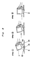
- Fig. 9 is a cross section of an engaging portion of a heating and cooking apparatus according to a second embodiment of the present invention in the state where an object 35 in the kneading trough 1 which is finished cooking is being taken out of the heating chamber 11 with the use of a protective glove 37 by a user 36.
- the foot part 2 of the kneading trough 1 is now fixedly secured to the to-be-engaged portion 3 in the heating chamber 11 through engagement therebetween.
- a lower end 41 of an operating lever 40 which forms a part of the handle 15 fixedly provided with the kneading trough 1 is entered into a second hole portion 43 formed in the to-be-engaged portion 3 and also into a through-hole 38 formed in the foot part 2 of the kneading trough 1 correspondingly to the second hole portion 43.
- the upper part of the operating levelr 40 is supported rotatably at a fulcrum 9 in the handle 15.
- the operating lever 40 is urged by a leaf spring 42 in a counterclockwise direction at the center of the fulcrum 9.
- the operation lever 40 which passes through a guide groove 39 formed in the handle 15 slides in the handle 15 along the guide groove 39.
- the projected portion 4 provided opposite to the handle 15 in the foot part 2 of the kneading trough 1 is fixedly inserted in the hole portion 12 in the depth of the heating chamber 11.
- the to-be-engaged portion 3 functions as a guide frame, and therefore if only the kneading trough 1 is installed, while being slid, into the heating chamber without confirming the position of the to-be-engaged portion 3, the hole portion 12 of the to-be-engaged portion 3 can be easily engaged with the projected portion 4 of the foot part 2 of the kneading trough 1.
- the kneading trough 1 should then be placed down onto the to-be-engaged portion 3, with the user's hand off, and the end portion 41 of the operating lever 40 passes through the second hole portion 43 of the to-be-engaged portion 3 to be fixedly inserted into the through-hole 38 of the kneading trough 1.
- the kneading trough and the to-be-engaged portion in the heating chamber are respectively formed into a polygonal shape, and therefore the engagement between the kneading trough and the to-be-engaged portion in the heating chamber can be easily accomplished with increased strength in the rotating direction, without any possibilities of rattlings or disengagement resulting from the friction therebetween.
- No complicated mechanism such as the lock mechanism or the like can be dispensed with for the reverse rotation of the kneading vane.
- the one side of the kneading trough is fixedly secured through the engagement or insertion of the projected portion into the hole portion of the to-be-engaged portion in the heating chamber, while the other side of the kneading trough is arranged to be fixed to the heating chamber by magnetic force. Accordingly, the kneading trough is able to be easily installed or taken from the heating chamber even in a box-shaped heating and cocking apparatus, so that a dangerous injury or burn may be avoided when it is too hot in the heating chamber immediately after cooking. If a handle is provided in the lateral wall of the kneading trough, the kneading trough can be held by one hand of the user, enhancing the using efficiency.
- the to-be-engaged portion in the heating chamber is formed by molded components made, for example, by aluminum die casting, the strength of the to-be-engaged portion is increased, and the bottom of the heating chamber can be less rough with little projections, thereby to increase the convenience in cleaning and maintenance from the hygienic viewpoint.
- the molded component can be smooth R, reducing the danger of a finger cutting or the like in cleaning.
- the detection unit provided at the side of the projected portion of the kneading trough ensures correct and positive operation of the detection switch. Therefore, the high-speed rotation when the kneading trough is not present in the heating chamber and/or the abnormal use when the kneading trough is present can be prevented, thus advantageously improving the safety of the apparatus.
- the kneading trough which can be put into the heating chamber directly with the raw materials for breads, cakes, etc. kneaded therein has the handle, so that the user can hold the kneading trough by one hand. Accordingly, the kneading trough is easy to be installed in or taken out of the heating chamber. Particularly, for example, when the heating chamber is high in temperatures immediately after cooking, it might be outly dangerous that the user holds the kneading trough by both hands so as to release the engagement of the kneading trough with the main body of the apparatus through necessary manipulations such as twisting or the like. Therefore, the heating and cooking apparatus of the present invention can be said to be highly safe and convenient for use.
- the kneading trough having the handle provided in the lateral wall thereof is convenient for use when it is cleaned after use.
- the handle of the kneading trough is made of so rigid material and secured to the kneading trough at at least opposite ends thereof that the kneading trough becomes accordingly solid and durable, realizing a long-life of the apparatus.
Landscapes
- Engineering & Computer Science (AREA)
- Food Science & Technology (AREA)
- Life Sciences & Earth Sciences (AREA)
- Chemical & Material Sciences (AREA)
- Chemical Kinetics & Catalysis (AREA)
- Baking, Grill, Roasting (AREA)
- Food-Manufacturing Devices (AREA)
- Cookers (AREA)
Applications Claiming Priority (6)
| Application Number | Priority Date | Filing Date | Title |
|---|---|---|---|
| JP33202387 | 1987-12-28 | ||
| JP332023/87 | 1987-12-28 | ||
| JP18024/88 | 1988-01-28 | ||
| JP63018024A JPH0767427B2 (ja) | 1988-01-28 | 1988-01-28 | 調理器 |
| JP178631/88 | 1988-07-18 | ||
| JP63178631A JP2532595B2 (ja) | 1988-07-18 | 1988-07-18 | 加熱調理器 |
Publications (3)
| Publication Number | Publication Date |
|---|---|
| EP0322836A2 true EP0322836A2 (fr) | 1989-07-05 |
| EP0322836A3 EP0322836A3 (en) | 1990-03-14 |
| EP0322836B1 EP0322836B1 (fr) | 1993-12-08 |
Family
ID=27282058
Family Applications (1)
| Application Number | Title | Priority Date | Filing Date |
|---|---|---|---|
| EP88121672A Expired - Lifetime EP0322836B1 (fr) | 1987-12-28 | 1988-12-24 | Méthode d'installation d'un pétrin dans un four et dispositif pour la mise en oeuvre de cette méthode |
Country Status (6)
| Country | Link |
|---|---|
| US (1) | US4870896A (fr) |
| EP (1) | EP0322836B1 (fr) |
| KR (1) | KR910007517B1 (fr) |
| AU (1) | AU597858B2 (fr) |
| CA (1) | CA1299628C (fr) |
| DE (1) | DE3886187T2 (fr) |
Cited By (5)
| Publication number | Priority date | Publication date | Assignee | Title |
|---|---|---|---|---|
| WO2001078569A1 (fr) * | 2000-04-18 | 2001-10-25 | Vorwerk & Co. Interholding Gmbh | Robot menager avec bol mixeur |
| EP2147601A1 (fr) * | 2008-07-24 | 2010-01-27 | Fagor, S. Coop. | Outil pour la préparation de pain pour un four domestique |
| WO2013178636A1 (fr) * | 2012-05-30 | 2013-12-05 | Arcelik Anonim Sirketi | Four équipé d'une fonction de cuisson de pain |
| EP2410862B1 (fr) * | 2009-03-24 | 2016-08-24 | De'Longhi Appliances S.r.l. | Appareil de maison pour faire du pain |
| CN112931545A (zh) * | 2021-02-07 | 2021-06-11 | 南安市丽迪家居用品有限公司 | 一种转塔式具有分区密封结构的烤炉 |
Families Citing this family (34)
| Publication number | Priority date | Publication date | Assignee | Title |
|---|---|---|---|---|
| AU618199B2 (en) * | 1988-06-14 | 1991-12-12 | Sharp Kabushiki Kaisha | High-frequency heating apparatus |
| CA1333194C (fr) * | 1988-06-14 | 1994-11-22 | Taisuke Morino | Appareil de chauffage a haute frequence |
| KR910001223B1 (ko) * | 1988-08-29 | 1991-02-26 | 삼성전자 주식회사 | 제빵기의 요구르트 제조장치 및 방법 |
| USD360104S (en) | 1993-11-05 | 1995-07-11 | Sunbeam Corporation | Bread making machine |
| US5392695A (en) * | 1994-04-05 | 1995-02-28 | Circulair, Inc. | Automatic breadmaking machine |
| USD438756S1 (en) | 1994-08-29 | 2001-03-13 | American Harvest, Inc. | Bread pan |
| US5839356A (en) * | 1994-07-15 | 1998-11-24 | American Harvest, Inc. | Automatic bread making machine |
| US5463937A (en) | 1994-10-25 | 1995-11-07 | The West Bend Company | Automatic breadmaker with plural kneading members |
| US5493955A (en) * | 1994-10-25 | 1996-02-27 | The West Bend Company | Automatic breadmaker with laterally-opening wide door |
| EP0709024A1 (fr) | 1994-10-25 | 1996-05-01 | The West Bend Company | Appareil de production de pain automatique comportant un moule latéral |
| US5694832A (en) * | 1995-01-06 | 1997-12-09 | Matsushita Electric Industrial Co., Ltd. | Automatic bread producing machine |
| US20010039884A1 (en) | 1997-07-07 | 2001-11-15 | Alan L. Backus | Simplified device to quickly cook food |
| US5855164A (en) * | 1998-05-21 | 1999-01-05 | Chiang; Hanh | Roasting apparatus easily convertible into a bread making apparatus |
| US7325484B1 (en) | 1998-12-21 | 2008-02-05 | Ronco Acquisition Corporation | Enclosed rotisserie with added convenience |
| US6173645B1 (en) | 1999-11-09 | 2001-01-16 | Alan L. Backus | Convenient food supporting vessel for use on a rotisserie cooking spit |
| US6170390B1 (en) | 1998-12-21 | 2001-01-09 | Alan L. Backus | Enclosed rotisserie with added convenience |
| US6450087B2 (en) | 1998-12-21 | 2002-09-17 | Alan L. Backus | Rotisserie oven having a shaped food basket |
| US6874408B2 (en) | 1998-12-21 | 2005-04-05 | Advantage Partners Ip, Llc | Rotisserie cooker |
| US6658991B2 (en) | 1998-12-21 | 2003-12-09 | Alan L. Backus | Barbeque grill spit assembly |
| US7021204B2 (en) | 1998-12-21 | 2006-04-04 | Backus Alan L | Enclosed rotisserie with detachable electronic components |
| US6988445B1 (en) | 1998-12-21 | 2006-01-24 | Advantage Partners, Llc | Enclosed rotisserie with added convenience |
| US6568316B1 (en) | 2001-12-05 | 2003-05-27 | Alan L. Backus | Rotisserie spit attachment |
| US6571690B1 (en) * | 2002-10-17 | 2003-06-03 | Tsang-Hung Hsu | Home yogurt making machine by directly incubating milk bottle therein |
| KR20040096136A (ko) * | 2003-05-07 | 2004-11-16 | 삼성전자주식회사 | 제빵기 |
| US6965095B1 (en) | 2004-09-20 | 2005-11-15 | Ronco Inventions, Llc | Rotisserie oven having horizontally and vertically oriented cooking elements |
| FR2902305B1 (fr) * | 2006-06-15 | 2013-07-26 | Seb Sa | Recipient de traitement thermiques d'aliments |
| FR2934484B1 (fr) * | 2008-08-01 | 2013-06-14 | Seb Sa | Cuve de preparation et de cuisson d'aliments pour appareil electromenager. |
| US20110174601A1 (en) * | 2010-01-20 | 2011-07-21 | Jin Yi Huang | Juicer Having Safety Mechanism With Its Handle |
| JP2011152272A (ja) * | 2010-01-27 | 2011-08-11 | Sanyo Electric Co Ltd | 自動製パン機 |
| US9655378B2 (en) | 2014-04-25 | 2017-05-23 | National Presto Industries, Inc. | Apparatus for preparing popcorn |
| US9826771B2 (en) * | 2015-01-16 | 2017-11-28 | National Presto Industries, Inc. | Apparatus and related methods for preparing popcorn |
| EP3085285B1 (fr) * | 2015-04-23 | 2019-06-12 | Whirlpool Corporation | Système de cuisson, en particulier pour des pâtes alimentaires, du riz et du pain |
| CN113842065B (zh) * | 2017-11-29 | 2022-06-28 | 九阳股份有限公司 | 一种食品加工机 |
| US20240315260A1 (en) * | 2023-03-22 | 2024-09-26 | I-Tech Usa, Inc. | Locking mechanism for bread machine |
Family Cites Families (12)
| Publication number | Priority date | Publication date | Assignee | Title |
|---|---|---|---|---|
| DE1001205B (de) * | 1952-07-31 | 1957-01-24 | Siemens Ag | Sicherheitseinrichtung fuer elektrisch angetriebene Geraete, z.B. Getraenkemixer, Zerkleinerungsgeraete u. dgl. |
| US3393900A (en) * | 1967-04-17 | 1968-07-23 | Proctor Silex Inc | Food mixer |
| US3892365A (en) * | 1971-07-23 | 1975-07-01 | Pierre Verdun | Apparatus for preparing food |
| JPS502034B2 (fr) * | 1971-09-22 | 1975-01-23 | ||
| US3786999A (en) * | 1972-01-11 | 1974-01-22 | Ronson Corp | Safety mechanism to prevent shaft coupling when blades are exposed in a blender |
| US4095751A (en) * | 1977-03-25 | 1978-06-20 | Oster Corporation | Slicing and shredding apparatus |
| US4629131A (en) * | 1981-02-25 | 1986-12-16 | Cuisinarts, Inc. | Magnetic safety interlock for a food processor utilizing vertically oriented, quadrant coded magnets |
| US4396159A (en) * | 1981-02-25 | 1983-08-02 | Cuisinarts, Inc. | Protective guide structure for preventing inadvertent actuation of a food processor with a tilted cover |
| DD205066A1 (de) * | 1982-02-18 | 1983-12-21 | Suhl Elektrogeraete Veb K | Aufnahmeanordnung fuer zusatzgeraete eines ruehrgeraetes |
| EP0302247B1 (fr) * | 1983-07-08 | 1992-02-05 | Hosiden Corporation | Moyen de pétrissage pour un dispositif de cuisson de pain |
| US4538509A (en) * | 1983-08-22 | 1985-09-03 | Hosiden Electronics Co., Ltd. | Automatic bread baking machine |
| CA1277548C (fr) * | 1985-10-12 | 1990-12-11 | Ojima, Tadasu | Appareil et methode pour faire du pain a la maison |
-
1988
- 1988-12-24 EP EP88121672A patent/EP0322836B1/fr not_active Expired - Lifetime
- 1988-12-24 DE DE88121672T patent/DE3886187T2/de not_active Expired - Lifetime
- 1988-12-26 KR KR1019880017494A patent/KR910007517B1/ko not_active Expired
- 1988-12-28 US US07/291,296 patent/US4870896A/en not_active Expired - Lifetime
- 1988-12-28 CA CA000587098A patent/CA1299628C/fr not_active Expired - Lifetime
- 1988-12-29 AU AU27558/88A patent/AU597858B2/en not_active Ceased
Cited By (6)
| Publication number | Priority date | Publication date | Assignee | Title |
|---|---|---|---|---|
| WO2001078569A1 (fr) * | 2000-04-18 | 2001-10-25 | Vorwerk & Co. Interholding Gmbh | Robot menager avec bol mixeur |
| US6640692B1 (en) | 2000-04-18 | 2003-11-04 | Vorwerk & Co. Interholding Gmbh | Kitchen machine with a stirrer vessel |
| EP2147601A1 (fr) * | 2008-07-24 | 2010-01-27 | Fagor, S. Coop. | Outil pour la préparation de pain pour un four domestique |
| EP2410862B1 (fr) * | 2009-03-24 | 2016-08-24 | De'Longhi Appliances S.r.l. | Appareil de maison pour faire du pain |
| WO2013178636A1 (fr) * | 2012-05-30 | 2013-12-05 | Arcelik Anonim Sirketi | Four équipé d'une fonction de cuisson de pain |
| CN112931545A (zh) * | 2021-02-07 | 2021-06-11 | 南安市丽迪家居用品有限公司 | 一种转塔式具有分区密封结构的烤炉 |
Also Published As
| Publication number | Publication date |
|---|---|
| KR890009343A (ko) | 1989-08-01 |
| EP0322836B1 (fr) | 1993-12-08 |
| DE3886187T2 (de) | 1994-04-07 |
| DE3886187D1 (de) | 1994-01-20 |
| CA1299628C (fr) | 1992-04-28 |
| AU597858B2 (en) | 1990-06-07 |
| US4870896A (en) | 1989-10-03 |
| KR910007517B1 (ko) | 1991-09-27 |
| EP0322836A3 (en) | 1990-03-14 |
| AU2755888A (en) | 1989-07-20 |
Similar Documents
| Publication | Publication Date | Title |
|---|---|---|
| US4870896A (en) | Installation method of a kneading trough in an oven and its apparatus | |
| EP0342307B1 (fr) | Appareil de cuisson | |
| JP2013253724A (ja) | 加熱調理器 | |
| JP5914273B2 (ja) | 加熱調理器 | |
| EP0389245B1 (fr) | Interrupteur horaire | |
| JP2532595B2 (ja) | 加熱調理器 | |
| JP6138888B2 (ja) | 加熱調理器 | |
| JP2013044509A (ja) | 加熱調理器 | |
| CN213464710U (zh) | 烹饪器具 | |
| JPH01259818A (ja) | 加熱調理器および加熱室への容器の装着方法 | |
| KR940007589Y1 (ko) | 오븐레인지의 회전대 정회전 구조 | |
| JP2964103B2 (ja) | 加熱調理器 | |
| KR200193607Y1 (ko) | 전자렌지 | |
| CN218500533U (zh) | 烤箱 | |
| JP5899087B2 (ja) | 加熱調理器 | |
| JP2537944B2 (ja) | 調理装置 | |
| JPH02122120A (ja) | 加熱調理器 | |
| KR900007791B1 (ko) | 고주파 가열장치의 히이타 전동장치 | |
| KR930002732B1 (ko) | 고주파 가열장치 | |
| JP2920789B2 (ja) | 加熱調理器 | |
| KR920003826B1 (ko) | 조리기 | |
| JP2565895Y2 (ja) | 加熱調理器 | |
| KR880002400Y1 (ko) | 전자 오븐 렌지의 회전조리구의 축결합장치 | |
| CN120959590A (zh) | 包括壳体和可拆卸烹饪器具的烹饪制备设备 | |
| JPH02161214A (ja) | 調理器 |
Legal Events
| Date | Code | Title | Description |
|---|---|---|---|
| PUAI | Public reference made under article 153(3) epc to a published international application that has entered the european phase |
Free format text: ORIGINAL CODE: 0009012 |
|
| 17P | Request for examination filed |
Effective date: 19881224 |
|
| AK | Designated contracting states |
Kind code of ref document: A2 Designated state(s): DE FR GB SE |
|
| PUAL | Search report despatched |
Free format text: ORIGINAL CODE: 0009013 |
|
| AK | Designated contracting states |
Kind code of ref document: A3 Designated state(s): DE FR GB SE |
|
| 17Q | First examination report despatched |
Effective date: 19920220 |
|
| GRAA | (expected) grant |
Free format text: ORIGINAL CODE: 0009210 |
|
| AK | Designated contracting states |
Kind code of ref document: B1 Designated state(s): DE FR GB SE |
|
| REF | Corresponds to: |
Ref document number: 3886187 Country of ref document: DE Date of ref document: 19940120 |
|
| ET | Fr: translation filed | ||
| PLBE | No opposition filed within time limit |
Free format text: ORIGINAL CODE: 0009261 |
|
| STAA | Information on the status of an ep patent application or granted ep patent |
Free format text: STATUS: NO OPPOSITION FILED WITHIN TIME LIMIT |
|
| 26N | No opposition filed | ||
| EAL | Se: european patent in force in sweden |
Ref document number: 88121672.5 |
|
| PGFP | Annual fee paid to national office [announced via postgrant information from national office to epo] |
Ref country code: SE Payment date: 19981207 Year of fee payment: 11 |
|
| PG25 | Lapsed in a contracting state [announced via postgrant information from national office to epo] |
Ref country code: SE Free format text: LAPSE BECAUSE OF NON-PAYMENT OF DUE FEES Effective date: 19991225 |
|
| EUG | Se: european patent has lapsed |
Ref document number: 88121672.5 |
|
| REG | Reference to a national code |
Ref country code: GB Ref legal event code: IF02 |
|
| PGFP | Annual fee paid to national office [announced via postgrant information from national office to epo] |
Ref country code: GB Payment date: 20071219 Year of fee payment: 20 Ref country code: FR Payment date: 20071210 Year of fee payment: 20 |
|
| PGFP | Annual fee paid to national office [announced via postgrant information from national office to epo] |
Ref country code: DE Payment date: 20071220 Year of fee payment: 20 |
|
| REG | Reference to a national code |
Ref country code: GB Ref legal event code: PE20 Expiry date: 20081223 |
|
| PG25 | Lapsed in a contracting state [announced via postgrant information from national office to epo] |
Ref country code: GB Free format text: LAPSE BECAUSE OF EXPIRATION OF PROTECTION Effective date: 20081223 |