EP0322851A2 - Vergaser für Brennkraftmaschine - Google Patents
Vergaser für Brennkraftmaschine Download PDFInfo
- Publication number
- EP0322851A2 EP0322851A2 EP88121696A EP88121696A EP0322851A2 EP 0322851 A2 EP0322851 A2 EP 0322851A2 EP 88121696 A EP88121696 A EP 88121696A EP 88121696 A EP88121696 A EP 88121696A EP 0322851 A2 EP0322851 A2 EP 0322851A2
- Authority
- EP
- European Patent Office
- Prior art keywords
- lever
- throttle
- carburetor
- fact
- cam
- Prior art date
- Legal status (The legal status is an assumption and is not a legal conclusion. Google has not performed a legal analysis and makes no representation as to the accuracy of the status listed.)
- Withdrawn
Links
Images


Classifications
-
- F—MECHANICAL ENGINEERING; LIGHTING; HEATING; WEAPONS; BLASTING
- F02—COMBUSTION ENGINES; HOT-GAS OR COMBUSTION-PRODUCT ENGINE PLANTS
- F02M—SUPPLYING COMBUSTION ENGINES IN GENERAL WITH COMBUSTIBLE MIXTURES OR CONSTITUENTS THEREOF
- F02M1/00—Carburettors with means for facilitating engine's starting or its idling below operational temperatures
- F02M1/08—Carburettors with means for facilitating engine's starting or its idling below operational temperatures the means to facilitate starting or idling becoming operative or inoperative automatically
- F02M1/10—Carburettors with means for facilitating engine's starting or its idling below operational temperatures the means to facilitate starting or idling becoming operative or inoperative automatically dependent on engine temperature, e.g. having thermostat
Definitions
- the present invention relates to a carburetor for an internal combustion engine, featuring a simplified control procedure for ensuring efficient operation and resetting of the carburettor at cold and normal engine temperatures respectively.
- the carburetor of an internal combustion engine is known to substantially comprise a choke tube supplied with fuel by a spray nozzle; a first throttle downstream from the choke tube, for regulating mixture supply to the engine; and a second throttle upstream from the choke tube for regulating the air supply.
- the second throttle When the engine is cold started, the second throttle must be closed, and the first opened just enough to supply the amount of mixture required for cold starting the engine.
- the second air supply throttle When the engine reaches normal running temperature, on the other hand, the second air supply throttle must be set wide open, whereas the opening on the first must be reduced from the cold starting to the idling speed position. Switching from the first to the second position must be made gradually, to prevent a sharp change in engine speed, and possible stalling of the engine.
- the second throttle is connected, via an appropriate transmission, to a hand control knob by which it is set, by the driver, to the closed position, when cold starting the engine, and subsequently to the fully open position when the engine reaches normal running temperature.
- Carburetors of the aforementioned type therefore demand a good deal of attention on the part of the driver, for ensuring gradual opening of the second throttle once the engine has been started.
- Some carburetors provide for closing and gradually opening the second air supply throttle automatically, but these are invariably highly complex, require frequent revision, and are unreliable.
- the aim of the present invention is to provide a carburetor for an internal combustion engine, designed to overcome the drawbacks typically associated with known carburetors of the aforementioned type.
- a carburetor for an internal combustion engine substantially comprising a choke tube supplied with fuel by a spray nozzle; a first throttle downstream from said choke tube, for regulating mixture supply to the engine; and a second throttle upstream from said choke tube, for regulating air supply to the same; characterised by the fact that it comprises: rotary cam means designed to control, subsequent to rotation, simultaneous displacement, according to predetermined laws, of said first and second throttles, from a first position, wherein the engine is cold started, to a second position wherein the engine is at normal running temperature; said cam means being set manually to said first position; at least a first actuator designed to move into a first position when the engine is cold started, and a second position when the engine is at normal running temperature; so that, when said first actuator switches from said first to said second position, and said cam means are set manually to said first position, said cam means are switched from said first to said second position; whereas, when said actuator switches from said second to said first
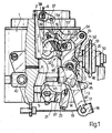
- the carburetor according to the present invention substantially comprises a body 1 in which is formed a vertical duct 2 housing a choke tube 3 supplied with fuel in known manner by a spray nozzle 4; a first throttle 5 downstream from said choke tube, and designed to regulate mixture supply to the engine; and a second throttle 6 upstream from said choke tube, and designed to regulate air supply to the same via duct 2.
- the carburetor according to the present invention also comprises rotary cam means indicated as a whole by 10 and designed to control simultaneous displacement of throttles 5 and 6 according to predetermined laws and as described hereinafter.
- Said means substantially comprise a lever 11 pivoting on a horizontal pin 12 secured to body 1.
- Said lever 11 presents a first arm 13 on which is formed a first cam 14 controlling said first throttle 5; and a second arm 15 on which is formed a second cam 16 controlling said second throttle 6.
- Said lever 11 also comprises a third arm 17 (overlapping arm 13 in Fig.1) the end 18 of which is connected mechanically to a manual control element, e.g. lead 19, whereby cam means 10 are set manually, as described hereinafter, into a first position (Fig.3) by turning lever 11 clockwise commencing from the Fig.1 position.
- Lead 19 is connected to a knob (not shown) conveniently located on the vehicle dashboard.
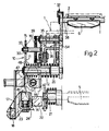
- Lever 11 is normally maintained in the Fig. 1 position by a spring 48 (Fig. 2) coaxial with pin 12 on which lever 11 pivots.
- Throttle 5 is integral with a shaft 21 fitted with a lever 22, the end of which presents a cam follower 23 resting on the curved active profile (Fig.1) of cam 14.
- Cam follower 23 conveniently presents an adjuster 24 (Fig.2).
- the active profile of second cam 16 is formed by the edge of an enclosed opening 30 formed on arm 15.
- Cam means 10 also comprise a cylindrical cam follower 33 integral with a lever 34 pivoting on a pin 35 and the free end of which acts on one end of a connecting rod 36, the other end of which is hinged to a crank 37 integral with shaft 38 of throttle 6.
- the distance between profile portions 31 and 32 of cam 16 is greater than the diameter of cylindrical cam follower 33.
- a helical spring 39 is connected to the free end of lever 34 for securing this in the clockwise-rotated position shown in Fig.1.
- a first actuator 42 (Fig. 3) for controlling cam means 10 substantially comprises a body housing a wax capsule which, as it increases in temperature, provides for axial displacement of a rod 43. Between rod 43 and lever 11 of cam means 10, there is inserted a lever 44 also pivoting on pin 12 and substantially comprising a tab 45 resting on a shoulder 46 of lever 11 for turning this anticlockwise. Tab 45 presents a threaded hole housing a screw 47, the end of which rests on the end of rod 43. Screw 47 is held permanently against the end of rod 43 by a spring 20 coaxial with pin 12 and designed to turn lever 44 clockwise.
- the carburetor according to the present invention also comprises a second actuator 50 controlled by the vacuum inside the intake manifold on the engine, and substantially comprising a rod 51 to which is hinged a first arm 52 of a lever pivoting on pin 35.
- a second arm 53 substantially perpendicular to arm 52, rests on a bent portion 54 of connecting rod 36, as shown clearly in Fig.2.
- actuator 50 is subjected, via an appropriate duct, to the vacuum inside the intake manifold on the engine, rod 51 turns arms 52 and 53 anticlockwise, so as to lower connecting rod 36.
- the carburetor according to the present invention operates as follows.
- the driver operates the knob connected to lead 19, so as to turn lever 11 clockwise from the Fig.1 to the Fig.3 position, wherein shoulder 46 of lever 11 contacts a respective shoulder on tab 45 of lever 44. Said so-called arming position of lever 11 is maintained by the friction on the transmission between the lead and control knob.
- cam follower 33 is detached from active profile portion 32 of cam 16; lever 34 is turned into the fully clockwise position, wherein air supply throttle 6 is closed; and the active profile of cam 14 contacts cam follower 23 of lever 22.
- the active profile of cam 14 is so selected, and cam follower 23 so regulated, as to correspond, in the Fig.3 configuration, to a predetermined opening on throttle 5, enabling a fairly high engine speed as required for cold starting.
- actuator 50 is operated so as to turn arms 52 and 53 anticlockwise.
- arm 53 moves connecting rod 36 down, so as to open throttle 6 by a predetermined amount.
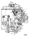
- Fig.4 shows the component configuration immediately following cold starting of the engine, wherein cam follower 33 contacts profile portion 31 of cam 16.
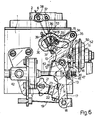
- lever 11 is turned further, thus causing upper profile portion 32 to act on cam follower 33, and so turn lever 34 clockwise for increasing the opening on air throttle 6, as shown in Fig.6.
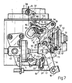
- rod 43 is in the rightmost position shown in Fig.7, corresponding to a full turn of lever 11; and the combined action of upper profile 32 of cam 16 and cam follower 33 has further turned lever 34 so as to fully open air throttle 6.
- the carburetor according to the present invention there seeminglyfore provides for cold starting the engine by simply exerting pull on lead 19 for arming the cold starting components on the device, after which, the rest is performed fully automatically, with no assistance from the driver.
- the carburetor according to the present invention is highly reliable and of extremely straightforward, low-cost design.
- actuator 42 comprising a wax capsule may be replaced by any other type of actuator capable of controlling axial displacement of rod 43 as the temperature of the engine increases.
- profiles of cams 14 and 16 controlling throttles 5 and 6 may be of any shape other than that described by way of example herein.
Landscapes
- Engineering & Computer Science (AREA)
- Chemical & Material Sciences (AREA)
- Combustion & Propulsion (AREA)
- Mechanical Engineering (AREA)
- General Engineering & Computer Science (AREA)
- Means For Warming Up And Starting Carburetors (AREA)
Applications Claiming Priority (2)
| Application Number | Priority Date | Filing Date | Title |
|---|---|---|---|
| IT6812887 | 1987-12-24 | ||
| IT8768128A IT1211629B (it) | 1987-12-24 | 1987-12-24 | Carburatore per un motore a combustione interna |
Publications (2)
| Publication Number | Publication Date |
|---|---|
| EP0322851A2 true EP0322851A2 (de) | 1989-07-05 |
| EP0322851A3 EP0322851A3 (de) | 1990-01-24 |
Family
ID=11308037
Family Applications (1)
| Application Number | Title | Priority Date | Filing Date |
|---|---|---|---|
| EP88121696A Withdrawn EP0322851A3 (de) | 1987-12-24 | 1988-12-27 | Vergaser für Brennkraftmaschine |
Country Status (3)
| Country | Link |
|---|---|
| EP (1) | EP0322851A3 (de) |
| BR (1) | BR8806881A (de) |
| IT (1) | IT1211629B (de) |
Family Cites Families (3)
| Publication number | Priority date | Publication date | Assignee | Title |
|---|---|---|---|---|
| GB571932A (en) * | 1943-02-18 | 1945-09-14 | Bendix Aviat Corp | Improvements in or relating to carburetters for internal combustion engines |
| US3837322A (en) * | 1973-07-30 | 1974-09-24 | Honda Motor Co Ltd | Carburetor choke |
| DE2903602C2 (de) * | 1979-01-31 | 1981-03-26 | Pierburg GmbH & Co KG, 41460 Neuss | Handstartvorrichtung für Vergaser von Brennkraftmaschinen |
-
1987
- 1987-12-24 IT IT8768128A patent/IT1211629B/it active
-
1988
- 1988-12-26 BR BR888806881A patent/BR8806881A/pt unknown
- 1988-12-27 EP EP88121696A patent/EP0322851A3/de not_active Withdrawn
Also Published As
| Publication number | Publication date |
|---|---|
| IT1211629B (it) | 1989-11-03 |
| IT8768128A0 (it) | 1987-12-24 |
| BR8806881A (pt) | 1989-08-29 |
| EP0322851A3 (de) | 1990-01-24 |
Similar Documents
| Publication | Publication Date | Title |
|---|---|---|
| US4463723A (en) | Apparatus for controllably opening a carburetor choke valve | |
| US5537964A (en) | Engine choke actuation system | |
| CS204978B2 (en) | Carburettor for the combustion engine | |
| US4094931A (en) | Carburetor assembly | |
| GB2219632A (en) | Control of carburettor choke and throttle valves | |
| US4181107A (en) | Carburetor choke valve controlling device | |
| US4172864A (en) | Carburetor | |
| GB2069055A (en) | Carburettor choke and throttle valve cold starting control device | |
| US2533551A (en) | Engine starting device | |
| US3868935A (en) | Automatic choke | |
| US3321193A (en) | Carburetor | |
| US2957465A (en) | Fast opening choke mechanism | |
| US3764119A (en) | Staged accelerator pump for two-stage carburetor | |
| KR0163374B1 (ko) | 연료분사펌프의 조속기 | |
| US3848857A (en) | Carburettors provided with a starting device with an eccentric flap valve | |
| US3943206A (en) | Carburetor temperature responsive throttle plate positioner | |
| JPS624665Y2 (de) | ||
| US4008297A (en) | Automatic starting device of carburetor | |
| JP2513774Y2 (ja) | 気化器のチョ―ク機構 | |
| GB2054049A (en) | Carburettor choke valve actuation | |
| US4169872A (en) | Carburetor | |
| US4333888A (en) | Carburetor accelerator pump stroke control | |
| US4385009A (en) | Automatic starter device for a double barrel carburator | |
| JP2528903Y2 (ja) | 気化器の自動始動装置 | |
| JPS6161954A (ja) | 気化器のオ−トチヨ−クシステム |
Legal Events
| Date | Code | Title | Description |
|---|---|---|---|
| PUAI | Public reference made under article 153(3) epc to a published international application that has entered the european phase |
Free format text: ORIGINAL CODE: 0009012 |
|
| AK | Designated contracting states |
Kind code of ref document: A2 Designated state(s): DE ES FR GB SE |
|
| PUAL | Search report despatched |
Free format text: ORIGINAL CODE: 0009013 |
|
| AK | Designated contracting states |
Kind code of ref document: A3 Designated state(s): DE ES FR GB SE |
|
| 17P | Request for examination filed |
Effective date: 19900627 |
|
| 17Q | First examination report despatched |
Effective date: 19910808 |
|
| STAA | Information on the status of an ep patent application or granted ep patent |
Free format text: STATUS: THE APPLICATION IS DEEMED TO BE WITHDRAWN |
|
| 18D | Application deemed to be withdrawn |
Effective date: 19920703 |