EP0323037B1 - Valve à solénoide - Google Patents
Valve à solénoide Download PDFInfo
- Publication number
- EP0323037B1 EP0323037B1 EP88311316A EP88311316A EP0323037B1 EP 0323037 B1 EP0323037 B1 EP 0323037B1 EP 88311316 A EP88311316 A EP 88311316A EP 88311316 A EP88311316 A EP 88311316A EP 0323037 B1 EP0323037 B1 EP 0323037B1
- Authority
- EP
- European Patent Office
- Prior art keywords
- pressure
- valve
- solenoid
- plunger
- outlet
- Prior art date
- Legal status (The legal status is an assumption and is not a legal conclusion. Google has not performed a legal analysis and makes no representation as to the accuracy of the status listed.)
- Expired - Lifetime
Links
- 239000012530 fluid Substances 0.000 claims description 44
- 238000004804 winding Methods 0.000 claims description 5
- 230000004907 flux Effects 0.000 claims description 3
- 230000000717 retained effect Effects 0.000 claims description 2
- 229910001220 stainless steel Inorganic materials 0.000 description 5
- 239000010935 stainless steel Substances 0.000 description 5
- 230000000712 assembly Effects 0.000 description 4
- 238000000429 assembly Methods 0.000 description 4
- 230000007423 decrease Effects 0.000 description 1
- 230000003247 decreasing effect Effects 0.000 description 1
- 238000011010 flushing procedure Methods 0.000 description 1
- 238000007789 sealing Methods 0.000 description 1
- 238000003466 welding Methods 0.000 description 1
Images
Classifications
-
- B—PERFORMING OPERATIONS; TRANSPORTING
- B60—VEHICLES IN GENERAL
- B60T—VEHICLE BRAKE CONTROL SYSTEMS OR PARTS THEREOF; BRAKE CONTROL SYSTEMS OR PARTS THEREOF, IN GENERAL; ARRANGEMENT OF BRAKING ELEMENTS ON VEHICLES IN GENERAL; PORTABLE DEVICES FOR PREVENTING UNWANTED MOVEMENT OF VEHICLES; VEHICLE MODIFICATIONS TO FACILITATE COOLING OF BRAKES
- B60T8/00—Arrangements for adjusting wheel-braking force to meet varying vehicular or ground-surface conditions, e.g. limiting or varying distribution of braking force
- B60T8/32—Arrangements for adjusting wheel-braking force to meet varying vehicular or ground-surface conditions, e.g. limiting or varying distribution of braking force responsive to a speed condition, e.g. acceleration or deceleration
- B60T8/34—Arrangements for adjusting wheel-braking force to meet varying vehicular or ground-surface conditions, e.g. limiting or varying distribution of braking force responsive to a speed condition, e.g. acceleration or deceleration having a fluid pressure regulator responsive to a speed condition
- B60T8/36—Arrangements for adjusting wheel-braking force to meet varying vehicular or ground-surface conditions, e.g. limiting or varying distribution of braking force responsive to a speed condition, e.g. acceleration or deceleration having a fluid pressure regulator responsive to a speed condition including a pilot valve responding to an electromagnetic force
- B60T8/3615—Electromagnetic valves specially adapted for anti-lock brake and traction control systems
- B60T8/3675—Electromagnetic valves specially adapted for anti-lock brake and traction control systems integrated in modulator units
-
- B—PERFORMING OPERATIONS; TRANSPORTING
- B60—VEHICLES IN GENERAL
- B60T—VEHICLE BRAKE CONTROL SYSTEMS OR PARTS THEREOF; BRAKE CONTROL SYSTEMS OR PARTS THEREOF, IN GENERAL; ARRANGEMENT OF BRAKING ELEMENTS ON VEHICLES IN GENERAL; PORTABLE DEVICES FOR PREVENTING UNWANTED MOVEMENT OF VEHICLES; VEHICLE MODIFICATIONS TO FACILITATE COOLING OF BRAKES
- B60T8/00—Arrangements for adjusting wheel-braking force to meet varying vehicular or ground-surface conditions, e.g. limiting or varying distribution of braking force
- B60T8/32—Arrangements for adjusting wheel-braking force to meet varying vehicular or ground-surface conditions, e.g. limiting or varying distribution of braking force responsive to a speed condition, e.g. acceleration or deceleration
- B60T8/34—Arrangements for adjusting wheel-braking force to meet varying vehicular or ground-surface conditions, e.g. limiting or varying distribution of braking force responsive to a speed condition, e.g. acceleration or deceleration having a fluid pressure regulator responsive to a speed condition
-
- B—PERFORMING OPERATIONS; TRANSPORTING
- B60—VEHICLES IN GENERAL
- B60T—VEHICLE BRAKE CONTROL SYSTEMS OR PARTS THEREOF; BRAKE CONTROL SYSTEMS OR PARTS THEREOF, IN GENERAL; ARRANGEMENT OF BRAKING ELEMENTS ON VEHICLES IN GENERAL; PORTABLE DEVICES FOR PREVENTING UNWANTED MOVEMENT OF VEHICLES; VEHICLE MODIFICATIONS TO FACILITATE COOLING OF BRAKES
- B60T8/00—Arrangements for adjusting wheel-braking force to meet varying vehicular or ground-surface conditions, e.g. limiting or varying distribution of braking force
- B60T8/32—Arrangements for adjusting wheel-braking force to meet varying vehicular or ground-surface conditions, e.g. limiting or varying distribution of braking force responsive to a speed condition, e.g. acceleration or deceleration
- B60T8/34—Arrangements for adjusting wheel-braking force to meet varying vehicular or ground-surface conditions, e.g. limiting or varying distribution of braking force responsive to a speed condition, e.g. acceleration or deceleration having a fluid pressure regulator responsive to a speed condition
- B60T8/36—Arrangements for adjusting wheel-braking force to meet varying vehicular or ground-surface conditions, e.g. limiting or varying distribution of braking force responsive to a speed condition, e.g. acceleration or deceleration having a fluid pressure regulator responsive to a speed condition including a pilot valve responding to an electromagnetic force
- B60T8/3615—Electromagnetic valves specially adapted for anti-lock brake and traction control systems
- B60T8/363—Electromagnetic valves specially adapted for anti-lock brake and traction control systems in hydraulic systems
- B60T8/3645—Electromagnetic valves specially adapted for anti-lock brake and traction control systems in hydraulic systems having more than one electromagnetic coil inside a common housing
-
- Y—GENERAL TAGGING OF NEW TECHNOLOGICAL DEVELOPMENTS; GENERAL TAGGING OF CROSS-SECTIONAL TECHNOLOGIES SPANNING OVER SEVERAL SECTIONS OF THE IPC; TECHNICAL SUBJECTS COVERED BY FORMER USPC CROSS-REFERENCE ART COLLECTIONS [XRACs] AND DIGESTS
- Y10—TECHNICAL SUBJECTS COVERED BY FORMER USPC
- Y10T—TECHNICAL SUBJECTS COVERED BY FORMER US CLASSIFICATION
- Y10T137/00—Fluid handling
- Y10T137/8593—Systems
- Y10T137/87169—Supply and exhaust
- Y10T137/87217—Motor
Definitions
- the invention relates to a valve assembly having valves controlled by solenoids to provide various connected and disconnected arrangements in a fluid system as specified in the preamble of claim 1, for example as disclosed in EP-A-0 256 272. It is particularly useful in a wheel lock control or anti-skid brake system (ABS).
- ABS wheel lock control or anti-skid brake system
- a solenoid valve assembly according to the present invention is characterised by the features specified in the characterising portion of claim 1.
- the two solenoid control valves are preferably placed in a single package and arranged in geometric series connection.
- the valve assembly preferably has four functional modes with three fluid ports. The four functional modes are controlled by energizing or de-energizing the solenoids in various combinations.
- When used in a wheel lock control or anti-skid brake system there is a pressure-input port, a pressure-output port, and a pressure-release port or exhaust port which releases fluid directly to a reservoir.
- the fluid connection between the input port and the output port, and the fluid connection between the output port and the pressure-release port, are within the valve assembly.
- the assembly preferably has a common chamber made of two thin-walled stainless steel tubes and a centre-channelled plunger stop to which the two tubes are attached at each end thereof. The channel arrangement provides the shortest fluid passage from the pressure-output port to the pressure-release port within the valve assembly whilst having a minimum fluid energy loss.
- the electrical connection and the direction of the coil windings of the two solenoids assist in forming a continuous enhancible magnetic flux pattern so that the resulting magnetic fields can provide enhanced performance.
- the centre thin-wall stainless steel tubes act as chambers which contain the valve plungers, which are also solenoid armatures, with pressurized fluid being within the tubes under certain conditions.
- the arrangement avoids axial loading against the thin-wall tubes and the tubes are strengthened so as to contain the fluid pressure therein by the position of the solenoid coils and coil housings immediately about each tube.
- the triple cascade orifice is positioned between the pressure-input port and the pressure-output port and includes three orifices provided in series, the third orifice being established by an opening between a ball valve and a cylindrical wall in which the ball valve is located when the ball is unseated so as to permit flow therepast.
- This arrangement provides sufficient fluid flow at highly compressed fluid pressures with the least pressure differential across each of the individual orifices, tending to eliminate fluid cavitation and to alleviate induced noise resulting therefrom.
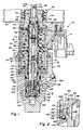
- Figure 1 is a cross-section view with parts broken away showing a solenoid valve assembly embodying the invention.
- Figure 2 is an enlarged fragmentary portion of Figure 1 as indicated by circle 2 on Figure 1.
- a solenoid valve assembly 10 is illustrated in Figure 1 as having a housing section 12 which includes an electrical connector 14. It also houses two solenoid assemblies 16 and 18 as well as at least portions of the valves and fluid passages controlled thereby. Assembly 10 also includes a housing section 20 which houses a portion of the solenoid assembly 16 as well as a normally-open valve controlled by that solenoid. The two solenoids are illustrated as being contained within a solenoid case assembly 22. The solenoid assemblies 16 and 18 are also associated with end plates 24 and 26, respectively, as well as a centre plunger stop support plate 28.
- Solenoid coil frames 30 and 32 respectively containing solenoid assemblies 16 and 18, engage the plates 24, 26 and 28 and co-operate therewith to bear the axial load in compressive-loading conditions so that the axial load is not carried through a solenoid coil 34 of solenoid assembly 16 or a solenoid coil 36 of solenoid assembly 18.
- the direction of coil windings in said solenoid coils 34, 36 and the direction of electrical current flowing through one of said solenoid coils when only the one of said solenoid coils is electrically energized are such that any magnetic field of said one electrically energized solenoid coil which influences an armature plunger of the other of said solenoid coils acts on that armature plunger to urge it in the axial direction opposite to the axial direction in which that armature plunger is magnetically urged by the other of said solenoid coils when said other solenoid coil is electrically energized.
- Solenoid assembly 16 has one end 38 of case assembly 22 crimped over a flange 40 of a normally-open valve housing 42. The other end 44 of case assembly 22 is similarly crimped about a flange 46 of a solenoid assembly cap 48.
- Cap 48 is illustrated as being provided with a multiple land sealing grommet 50 which extends through a tube-like bottom portion 52 of a reservoir 54 so that an upper end 56 of cap 48 opens into the reservoir 54 and the grommet 50 effectively seals between the cap 48 and the reservoir portion 52.
- Reservoir 54 is preferably the reservoir for a master cylinder and a booster of a brake system as well as for an ABS system of which the solenoid valve assembly herein disclosed and claimed is preferably a part.
- Plunger stop assembly 58 includes a stop 60 and stainless steel tubes 62 and 64.
- Stop 60 has a through passage 66 formed axially therethrough and having slightly enlarged passage ends 68 and 70.
- a spring 72 is positioned in passage end 68 and abuts a shoulder formed at the bottom portion thereof.
- Another spring 74 is similar positioned in passage end 70.
- a centre portion of plunger stop 60 is suitably slotted or grooved so as to receive at least a part of plate 28 therein to anchor and locate the plunger stop assembly 58 axially and radially.
- An outer end 76 of tube 62 extends into the valve housing 42, and an outer end 78 of tube 64 extends into the solenoid assembly cap 48.
- the cylindrical spaces outwardly of the plunger stop 60 and the ends 76 and 78 of the stainless steel tubes provide cylinders.
- the inner ends of the stainless steel tubes 62 and 64 are secured to the plunger stop 60 in any suitable manner, for example by welding.
- the electrical connector 14 has suitable terminals and connecting wires arranged for energization and de-energization of each of the solenoid coils 34 and 36. These coils are wound in opposite directions for reasons to be described hereinafter.
- Solenoid assembly 16 has a solenoid armature plunger 79 which is reciprocably received within tube 62 and has axially-extending passages 80 which permit fluid flow therepast.
- Spring 68 is in engagement with an inner end 82 of plunger 79 so as to urge that plunger outwardly of the tube 62.
- a rod 84 has one end secured to plunger 79, with the other end extending outward of tube 62 and into a portion of the valve housing 42.
- Rod 84 is provided with a head 86 which controls the condition of a normally-open valve 88, described in greater detail below.
- Solenoid assembly 18 has an armature plunger 90 reciprocably received for axial movement in tube 64.
- Spring 74 engages plunger 90 and urges that plunger outwardly of tube 64.
- Plunger 90 also has a passageway 92 formed therethrough which is in continuous fluid communication with passage of the plunger stop 60.
- Plunger 90 is formed to provide a valve head 94 which is a part of a normally-closed valve 96.
- a seat member 98 is sealingly mounted in the outer end 78 of tube 64 and has a restrictive orifice passageway 100 formed therethrough.
- the end of passageway 100 facing valve head 94 is formed as a valve seat 102, and valve head 94 is normally in engagement with valve seat 102 to maintain passageway 100 closed.
- the seat member 98 is provided with a seal 104 which prevents leakage between the seat member and the inner wall of tube 64.
- the other end of seat member 98 is engaged by the inner end of a plug 106 which is threaded into cap 48 so as to provide the appropriate axial position of seat member 98.
- Plug 106 has a recess 108 formed therethrough in continuous fluid communication with passageway 100.
- the upper end of recess 108 is provided with a port 110 which is the release port of the assembly.
- Port 110 opens into the interior of reservoir 54. It can be readily seen that any fluid passing through passageway 100 and recess 108 will then be discharged directly into the reservoir.
- Valve housing 42 has a centre wall 112 provided with a passageway 114 extending axially therethrough.
- Rod 84 extends through this passageway but is somewhat smaller in diameter than the diameter of the passageway so that fluid communication is maintained between the interior of tube 62 and the other side of the centre wall 112.
- the rod head 86 On the other side of wall 112 is located the rod head 86 which is axially spaced slightly from that wall.
- a plug 116 is inserted in an outer opening 118 of valve housing 42 and limits axial outward movement of the valve head 86.
- Plug 116 has a passage 120 extending axially therethrough, with a filter 122 held in the outer end of passage 120 by a retainer 124.
- passage 120 is connected through the filter 122 to a pressure output port 126 provided in a part of housing section 20 in which the valve housing 42 and the plug 116 are mounted.
- valve housing centre wall 112 is of a decreased diameter in relation to valve housing ends 128 and 130 so that an annular chamber 132 is formed thereabout, this chamber being defined on its outer circumference by a portion of a cylinder wall 134 of a cylinder-like recess in housing section 20 into which the valve housing 42 is mounted.
- Suitable seals 136 and 138 are respectively provided on valve housing ends 128 and 130 so as to seal the annular chamber 132 relative to the pressure-output port 126 and the portion of housing 20 containing a part of the solenoid assembly 16.
- annular chamber 132 is in continuous fluid communication with a passage 146 in housing section 20 which is directly connected to a pressure-input port 148.
- Passage 136′ has another portion thereof formed to provide a second orifice 150 which extends parallel to the axis of the valve housing 42 and opens to provide a tapered valve seat 152 and a valve cylindrical wall 154, which in turn is fluid-connected to the passage 120 and pressure-output port 126 through filter 122.
- the normally-open ball-check valve 88 (axially spaced from the solenoid 16) is positionally retained within a cylindrical wall 154 so as to be engageable with tapered valve seat 152.
- Another L-shaped passage 158 in the valve housing centre wall 112 connects the annular chamber 132 with the pressure-output port 126 at all times.
- Ball-check valve 160 prevents reverse flow from the annular chamber 132 to the pressure-output port 126.
- a portion of passage 158 adjacent the valve seat of ball-check valve 160 is an orifice which will permit flow from the pressure-output port 126 to the pressure-input port when the pressure at the pressure-output port 126 is trying to be at a greater value than that of the input port.
- valve 160 and passage 158 prevent the pressure at the pressure-output port 126 from being greater at any time than that of the pressure at the pressure-input port 148.
- the three orifices 140, 150 and 156 between the pressure-input port 148 and the pressure-output port 126 provide a triple cascade orifice configuration which functions effectively and quietly in high pressure applications. At the same time it permits a sufficiently high fluid flow at highly compressed fluid pressures with the least pressure differential across each individual orifice, hence minimizing fluid cavitation and alleviating noise induced from such cavitation.
- the normal, de-energized, position of the valves in the assemblies is the position for normal pressure applied from the pressure-input port 148 to the pressure-output port 126 through the normally-open valve 88. This occurs when both solenoid coils 34 and 36 are de-energized so that valve 88 is opened and valve 96 is closed. Input pressure will also be conducted through the passageway 114 and past plunger 79, into passage 66 and passageway 92. However, the normally-closed valve 96 prevents that input pressure from being conducted to the reservoir 54 through port 110.
- the solenoid coil 34 controlling the normally-open valve 88 is energized, moving plunger 79 towards plunger stop 60, and moving rod head 86 so that it engages the ball valve 88 and moves that valve, holding that valve seated against the valve seat 152. This therefore closes off the input pressure in port 148, and holds the output port pressure in port 126 to the pressure therein at the time valve 88 was closed. Since valve 96 remains closed, the pressure in the output port 126 neither decreases nor increases.
- the solenoid coils 34 and 36 are both energized, closing or keeping valve 88 closed as in the previous state, and moving plunger 90 toward the plunger stop 60 to open valve 96.
- the output port pressure is then connected through passage 120 and passage way 114 as well as passage 66 and passageway 92 to the restrictive orifice passage 100 which controls rate of flow of fluid therethrough, after which the fluid enters the reservoir 54 through the release port 110.
- the pressure apply mode may be re-instituted by de-energizing both solenoid coils, returning the valves to their respective normally-open and normally-closed positions.
- a trapped air bleed mode is established by de-energizing coil 34, if it is energized, and energizing coil 36. This opens both valves 88 and 96, allowing the system to be bled, with the flow of fluid under pressure from the input port assisting in flushing any trapped air out of the assembly. Once the assembly is bled, both solenoids are then normally de-energized to return the assembly so that it may again permit the application of pressure from input port 148 to output port 126.
Landscapes
- Physics & Mathematics (AREA)
- Engineering & Computer Science (AREA)
- Electromagnetism (AREA)
- Fluid Mechanics (AREA)
- Transportation (AREA)
- Mechanical Engineering (AREA)
- Magnetically Actuated Valves (AREA)
- Regulating Braking Force (AREA)
- Valves And Accessory Devices For Braking Systems (AREA)
Claims (6)
- Ensemble (10) de soupape à électroaimant comprenant un boîtier (12, 20), une entrée (148) de pression, une sortie (126) de pression, un orifice (110) d'échappement, un premier électroaimant (16) ayant un premier plongeur (79) pouvant être actionné par électro-aimant ; un second électro-aimant (18) ayant un second plongeur (90) pouvant être actionné par électro-aimant, placé dans l'alignement axial du premier électro-aimant (16) et du premier plongeur (79) ; un élément (58) de butée de plongeur et de guidage, comprenant un élément de butée (60) positionné axialement entre les plongeurs (79, 90) et des moyens de guidage tubulaire (62, 64) fixés à l'élément de butée (60) et faisant saillie sur cet élément, le premier plongeur (79) et le second plongeur (90) étant respectivement logés mobiles en mouvement alternatif dans ces moyens, l'élément de butée (60) présentant un perçage (66) s'étendant axialement, qui le traverse ; un permier boîtier (42) de soupape ayant intérieurement un premier moyen formant soupape (88) normalement ouverte, espacé axialement du premier électro-aimant (16) et positionné dans un circuit de fluide entre l'entrée (148) de pression et la sortie (126) de pression, et ayant un élément (86) de fermeture de soupape fixé au premier plongeur (79) et qui se déplace avec lui lorsque le premier électro-aimant (16) est excité, pour fermer le premier moyen formant soupape (88) ; un moyen de passage (114) prévu dans le premier boîtier (42) de soupape dans l'aligenment axial du premier plongeur (79) et qui maintient une communication fluidique continue entre la sortie de pression (126) et le passage axial (66) formé dans l'élément de butée (60), à travers le premier guide tubulaire (62) ; et un second moyen (96) formant soupape normalement fermée comprenant un siège (102) de soupape prévu dans le second guide tubulaire (64), dans une position espacée axialement dudit élément de butée (60), avec le second plongeur (90) positionné axialement entre eux, un élément (94) de soupape formé sur le second plongeur (90) et normalement appuyé sur le siège (102) de soupape pour fermer le second moyen (96) formant soupape et pouvant se déplacer axialement lorsque le second électro-aimant (18) est excité pour ouvrir le second moyen (96) formant soupape, le second plongeur (90) établissant une communication fluidique entre le passage axial (66) de l'élément de butée et ledit élément (94) de soupape, et un passage (100) formant orifice d'étranglement qui s'étend à travers ledit siège (102) de soupape et est en communication fluidique avec ledit orifice (110) d'échappement ; les électro-aimants (16, 18) pouvant être sélectivement excités et désexcités pour ouvrir et fermer sélectivement les premier et second moyens formant soupapes (88, 96) et pour commander de cette façon la pression du fluide dans la sortie (126) de pression dans les modes d'application de pression, de maintien de pression, de relâchement de pression et de purge d'air, de fonctionnement dudit ensemble de soupapes à électro-aimants, caractérisée en ce que, dans cet ensemble (10), les moyens de guidage tubulaires comprennent des premier et second guides tubulaires (62, 64) ; il est prévu des premier et second ressorts (72, 74) de plongeur s'étendant l'un à l'opposé de l'autre et qui sollicitent respectivement les premier et second plongeurs (79, 90) dans le sens qui les éloigne axialement dudit élément de butée (60) ; il est prévu une plaque (28) portée par l'élément de butée (70) entre les guides tubulaires (62, 64) pour ancrer et positionner l'ensemble (58) de butée de plongeurs dans les directions axiale et radiale à l'intérieur du boîtier (12, 20) ; et le second plongeur (90) comporte un passage (92) qui le traverse en établissant la communication fluidique entre le passage axial (66) de l'élément de butée et l'élément (94) de soupape.
- Ensemble de soupape à électro-aimant selon la revendication 1, caractérisé en ce que le premier boîtier (42) de soupape renferme en outre une soupape anti-retour (160) non sollicitée par ressort, entre l'entrée (148) de pression et la sortie (126) de pression et qui subit l'action de pressions qui y règnent de manière à s'ouvrir lorsque la pression régnant dans la sortie (126) de pression excède la pression régnant dans l'entrée (148) de pression pour limiter la pression régnant dans la sortie (126) de pression à la pression régnant dans l'entrée (148) de pression, et à se fermer lorsque la pression régnant dans l'entrée (148) de pression excède la pression régnant dans la sortie (126) de pression.
- Ensemble de soupape à électro-aimant selon la revendication 1, caractérisé en ce que le premier boîtier (42) de soupape contient un dispositif d'orifice triple en cascade entre l'entrée (148) de pression et la sortie (126) de pression, défini par un premier orifice (140) de plaque mince, un second orifice (150) de passage d'écoulement étranglé et une soupape-bille (88) retenue dans un siège (152) de soupape à section décroissante qui constitue au moins une partie du moyen formant soupape, l'ouverture de la soupape-bille (88) dans le siège (152) de soupape à section décroissante formant un troisième orifice (156) à écoulement étranglé, le dispositif à orifice triple en cascade laissant passer un débit de fluide suffisant en présence de hautes pressions de fluide à l'entrée (148) de pression et établissant des différences de pression étagées entre les deux côtés de chacun des premier, second et troisième orifices (140, 150, 156), en éliminant sensiblement la cavitation du fluide et en atténuant les bruits induits qui en résulteraient.
- Ensemble de soupape à électro-aimant selon la revendication 1, caractérisé en ce que les premier et second électro-aimants (16, 18) comprennent une première et seconde bobines (34, 36) d'électro-aimant, enroulées l'une en sens inverse de l'autre, alignées axialement et pouvant être sélectivement excitées et désexcitées électriquement, ces bobines ayant leurs extrémités adjacentes justaposées l'une à l'autre ; les premier et second plongeurs (79, 90) sont des plongeurs d'armature d'électro-aimant positionnés coaxialement, logés respectivement dans les première et seconde bobines d'électro-aimant (34, 36) ; le premier boîtier (42) de soupape et un second boîtier (48) de soupape qui contient le second moyen (96) formant soupape normalement fermée sont positionnés dans l'alignement axial des plongeurs (79, 90) à l'extérieur des extrémités opposées des bobines (34, 36) d'électro-aimant mais adjacents aux extrémités opposées de ces bobines et renferment respectivement la première et la seconde soupapes (88, 96) ; l'entrée (148) de pression est en communication fluidique avec la première soupape (88) sur le côté d'entrée de celle-ci et la sortie (126) de pression est en communication fluidique avec la première soupape (88) sur le côté de sortie de celle-ci ; la seconde soupape (96) a son côté d'entrée en communication fluidique permanente avec le côté de sortie de la première soupape (88) ; et l'orifice (110) d'échappement de pression est en communication fluidique permanente avec le côté de sortie de la seconde soupape (96) ; l'ensemble étant adapté pour travailler dans un premier mode, d'application de la pression, dans lequel les deux bobines (34, 36) d'électro-aimant sont désexcitées et la première soupape (88) est ouverte et la seconde soupape (96) fermée pour conduire le fluide hydraulique sous pression de l'entrée (148) de pression à la sortie (126) de pression lorsque la sortie (126) de pression est reliée à un moyen commandé par une pression de fluide hydraulique ; l'ensemble étant adapté pour travailler dans un second mode de maintient de la pression, dans lequel la première bobine (34) d'électro-aimant est excitée électriquement et la seconde bobine (36) d'electro-aimant est désexcitée, les première et seconde soupapes (88, 96) sont fermées pour maintenir la pression de fluide hydraulique dans la sortie (126) de pression à la pression présente dans cette sortie lorsque la première soupape (88) est fermée ; l'ensemble étant adapté pour travailler dans un troisième mode, de relâchement de la pression, dans lequel les deux bobines (34, 36) d'électro-aimant sont excitées électriquement et la première soupape (88) est fermée et la seconde soupape (96) ouverte pour relâcher la pression de fluide hydraulique de la sortie (126) de pression ; et l'ensemble étant adapté pour travailler dans un quatrième mode, de purge d'air, dans lequel la première bobine (34) d'électro-aimant est désexcitée et la seconde bobine (36) d'électro-aimant est excitée électriquement et les première et seconde soupapes (88, 96) sont ouvertes pour purger l'air de l'ensemble (10) ainsi que de l'entrée (148) de pression et de la sortie (126) de pression et sont ainsi adaptées pour purger aussi l'air du fluide hydraulique présent dans un quelconque des dispositifs hydrauliques qui peuvent être raccordés à l'entrée (148) de pression et à la sortie (126) de pression.
- Ensemble de soupape à électro-aimant selon la revendication 4, caractérisé en ce que le sens d'enroulement desdites bobines (34, 36) d'électro-aimant et le sens du passage du courant électrique qui circule dans une première desdites bobines (34, 36) d'électro-aimant lorsque seule cette première des bobines (34, 36) d'électro-aimant est excitée électriquement, sont tels que tout flux magnétique de cette première bobine d'électro-aimant excitée électriquement qui influe sur le plongeur d'armature de l'autre des bobines d'électro-aimant agisse sur ce plongeur d'armature pour le solliciter dans le sens axial opposé au sens axial dans lequel ce plongeur d'armature est sollicité magnétiquement par l'autre des bobines d'électro-aimant lorsque cette autre bobine d'électro-aimant est excitée électriquement.
- Ensemble de soupape à électro-aimant selon la revendication 4, caractérisé en ce que le sens de l'enroulement des bobines (34, 36) d'électroaimant et le sens du passage des courants électriques qui y circulent lorsque les deux bobines (34, 36) d'électro-aimant sont excitées électriquement sont tels que les lignes de flux magnétiques de ces bobines qui sont engendrées à leurs extrémités adjacentes se renforcent mutuellement.
Applications Claiming Priority (2)
| Application Number | Priority Date | Filing Date | Title |
|---|---|---|---|
| US07/138,179 US4821770A (en) | 1987-12-28 | 1987-12-28 | Solenoid valve assembly |
| US138179 | 1993-10-14 |
Publications (3)
| Publication Number | Publication Date |
|---|---|
| EP0323037A2 EP0323037A2 (fr) | 1989-07-05 |
| EP0323037A3 EP0323037A3 (en) | 1989-08-16 |
| EP0323037B1 true EP0323037B1 (fr) | 1992-11-04 |
Family
ID=22480828
Family Applications (1)
| Application Number | Title | Priority Date | Filing Date |
|---|---|---|---|
| EP88311316A Expired - Lifetime EP0323037B1 (fr) | 1987-12-28 | 1988-11-30 | Valve à solénoide |
Country Status (5)
| Country | Link |
|---|---|
| US (1) | US4821770A (fr) |
| EP (1) | EP0323037B1 (fr) |
| CA (1) | CA1308625C (fr) |
| DE (1) | DE3875712T2 (fr) |
| ES (1) | ES2035321T3 (fr) |
Families Citing this family (23)
| Publication number | Priority date | Publication date | Assignee | Title |
|---|---|---|---|---|
| US4946230A (en) * | 1988-04-27 | 1990-08-07 | Mazda Motor Corporation | Method and an apparatus for charging an anti-lock brake system with brake liquid |
| US4938545A (en) * | 1989-03-13 | 1990-07-03 | General Motors Corporation | ABS solenoid/isolation valve integration into single-ended solenoid body, using pump pressure actuation |
| DE3934806C1 (fr) * | 1989-10-19 | 1991-06-06 | Mercedes-Benz Aktiengesellschaft, 7000 Stuttgart, De | |
| US5123718A (en) * | 1990-04-06 | 1992-06-23 | G. W. Lisk Company, Inc. | Valve for automatic brake system |
| JP2519922Y2 (ja) * | 1990-06-28 | 1996-12-11 | 株式会社ユニシアジェックス | アンチスキッドブレーキ装置 |
| US5125432A (en) * | 1990-08-08 | 1992-06-30 | Honda Giken Kogyo Kabushiki Kaisha | Electromagnetic valve device having two electromagnetic valves |
| US5184644A (en) * | 1991-05-30 | 1993-02-09 | Coltec Industries Inc. | Solenoid operated pressure regulating valve |
| US5218996A (en) * | 1992-04-06 | 1993-06-15 | Fasco Controls Corporation | Three-way three-position solenoid valve |
| US5306076A (en) * | 1992-05-20 | 1994-04-26 | G. W. Lisk Company, Inc. | Proportional control valve with pressure compensation |
| US5318354A (en) * | 1992-05-20 | 1994-06-07 | C. W. Lisk Company, Inc. | Proportional control valve with differential sensing area |
| US5887956A (en) * | 1993-09-28 | 1999-03-30 | Itt Automotive Europe Gmbh | Hydraulic brake system with slip control |
| DE19531468B4 (de) * | 1995-08-26 | 2007-05-24 | Robert Bosch Gmbh | Hydraulikaggregat für eine Bremsanlage mit einer Blockierschutzeinrichtung |
| US6431208B1 (en) | 2000-09-01 | 2002-08-13 | Delphi Technologies Inc. | Combined full function ABS valve |
| US6907901B2 (en) * | 2002-06-03 | 2005-06-21 | Borgwarner Inc. | Solenoid control valve |
| US20080169439A1 (en) * | 2006-12-18 | 2008-07-17 | Borgwarner Inc. | Integrated two-stage low-leak control valve |
| CN101795910A (zh) * | 2007-09-04 | 2010-08-04 | 丰田自动车株式会社 | 常闭电磁阀、制动控制系统、用于常闭电磁阀的控制方法和电磁阀 |
| US20090159133A1 (en) * | 2007-12-19 | 2009-06-25 | Midwest Sealing Products, Inc. | Electro-Mechanically Controlled Ceramic Based Proportional Valve |
| US8322376B2 (en) * | 2008-06-09 | 2012-12-04 | Bendix Commercial Vehicle Systems, Llc | Solenoid valve |
| CN104545445A (zh) * | 2013-10-12 | 2015-04-29 | 通用国际企业有限公司 | 牛奶蒸汽机 |
| DE102017217791A1 (de) * | 2017-10-06 | 2019-04-11 | Continental Teves Ag & Co. Ohg | Ventilanordnung und Bremssystem |
| US10424429B2 (en) | 2017-12-18 | 2019-09-24 | GM Global Technology Operations LLC | Long stroke linear solenoid |
| JP7104530B2 (ja) * | 2018-03-13 | 2022-07-21 | Kyb株式会社 | ソレノイド、電磁弁、及び緩衝器 |
| IT202000021793A1 (it) * | 2020-09-16 | 2022-03-16 | Lavazza Luigi Spa | Dispositivo per riscaldare e montare latte |
Family Cites Families (11)
| Publication number | Priority date | Publication date | Assignee | Title |
|---|---|---|---|---|
| CH543029A (fr) * | 1972-04-04 | 1973-10-15 | Lucifer Sa | Valve à trois voies pour fluide |
| DE2556023A1 (de) * | 1975-12-12 | 1977-06-23 | Bosch Gmbh Robert | Blockierschutzeinrichtung |
| JPS565872U (fr) * | 1979-06-26 | 1981-01-19 | ||
| US4486053A (en) * | 1980-11-04 | 1984-12-04 | Clayton Dewandre Company Limited | Solenoid operated valves |
| SE459080B (sv) * | 1982-11-20 | 1989-06-05 | Honda Motor Co Ltd | Solenoidventil |
| JPS6033158A (ja) * | 1983-07-29 | 1985-02-20 | Toyota Motor Corp | 車両用アンチスキッドブレ−キ装置 |
| DE3519348C2 (de) * | 1985-05-30 | 1996-06-20 | Festo Kg | Eine lineare Vorschubbewegung erzeugende Einrichtung |
| JPS6243347A (ja) * | 1985-08-22 | 1987-02-25 | Akebono Brake Ind Co Ltd | アンチスキツド制御装置 |
| JPH0631643B2 (ja) * | 1985-09-19 | 1994-04-27 | アイシン精機株式会社 | 流路流量切換電磁弁 |
| US4674536A (en) * | 1986-04-25 | 1987-06-23 | Sealed Power Corporation | Electrohydraulic valves for use in a system |
| GB8618301D0 (en) * | 1986-07-26 | 1986-09-03 | Eaton Sa Monaco | Three-port fluid valve |
-
1987
- 1987-12-28 US US07/138,179 patent/US4821770A/en not_active Expired - Fee Related
-
1988
- 1988-11-01 CA CA000581809A patent/CA1308625C/fr not_active Expired - Lifetime
- 1988-11-30 ES ES198888311316T patent/ES2035321T3/es not_active Expired - Lifetime
- 1988-11-30 DE DE8888311316T patent/DE3875712T2/de not_active Expired - Fee Related
- 1988-11-30 EP EP88311316A patent/EP0323037B1/fr not_active Expired - Lifetime
Also Published As
| Publication number | Publication date |
|---|---|
| DE3875712T2 (de) | 1993-03-18 |
| US4821770A (en) | 1989-04-18 |
| ES2035321T3 (es) | 1993-04-16 |
| EP0323037A2 (fr) | 1989-07-05 |
| EP0323037A3 (en) | 1989-08-16 |
| CA1308625C (fr) | 1992-10-13 |
| DE3875712D1 (de) | 1992-12-10 |
Similar Documents
| Publication | Publication Date | Title |
|---|---|---|
| EP0323037A2 (fr) | Valve à solénoide | |
| EP0997363B1 (fr) | Soupape pilote pour unité de commande hydraulique d'un système de freinage pour véhicules | |
| US4620565A (en) | Integrated three way and isolation solenoid valve | |
| US5203617A (en) | Electromagnetically-actuated 2/2-way valve, for hydraulic motor vehicle brake systems having an anti-skid and traction control apparatus | |
| US5738142A (en) | Pressure holding directional control valve | |
| US5076538A (en) | Electromagnetically operated valve, especially for anti-lock systems in motor vehicles | |
| KR100400797B1 (ko) | 제어가능한밸브 | |
| US5605386A (en) | Solenoid valve for slip-controlled hydraulic brake systems in motor vehicles | |
| US5934766A (en) | Magnetically operated, multi-position, pressure control valve having integral metering orifice | |
| EP0849514B1 (fr) | Soupape de régulation de la pression électromagnétique mono-étage avec moteur à force variable | |
| KR0127551B1 (ko) | 앤티로크 브레이크 시스템용 솔레노이드 밸브 및 제조방법 | |
| US4860794A (en) | Single ended solenoid valve assembly | |
| US5439279A (en) | Vehicular anti-lock brake system hydraulic control unit | |
| US5711583A (en) | Magnetic control valve for a slip-controlled hydraulic brake system for motor vehicles | |
| US6471305B1 (en) | Isolation valve armature configured to reduce bernoulli force during normal braking operation | |
| US6390444B1 (en) | Two-stage parallel spring solenoid valve | |
| US5618087A (en) | 2-position 3-way solenoid valve, modulator and anti-lock brake system with the valve | |
| US5681097A (en) | Hydraulic control unit for vehicular anti-lock brake and traction control systems | |
| KR102840705B1 (ko) | 2 단 솔레노이드 밸브 | |
| US5641211A (en) | Pressure control valve for hydraulic slip-controlled brake system | |
| US4987923A (en) | Solenoid valve | |
| JPH0631643B2 (ja) | 流路流量切換電磁弁 | |
| US5649748A (en) | Electromagnetically actuated valve for slip-controlled hydraulic brake systems in motor vehicles | |
| US5630569A (en) | Electromagnetically actuated valve for slip-controlled hydraulic brake systems in motor vehicles | |
| US4944331A (en) | Solenoid valve |
Legal Events
| Date | Code | Title | Description |
|---|---|---|---|
| PUAI | Public reference made under article 153(3) epc to a published international application that has entered the european phase |
Free format text: ORIGINAL CODE: 0009012 |
|
| PUAL | Search report despatched |
Free format text: ORIGINAL CODE: 0009013 |
|
| AK | Designated contracting states |
Kind code of ref document: A2 Designated state(s): DE ES FR GB IT |
|
| AK | Designated contracting states |
Kind code of ref document: A3 Designated state(s): DE ES FR GB IT |
|
| 17P | Request for examination filed |
Effective date: 19890904 |
|
| 17Q | First examination report despatched |
Effective date: 19910130 |
|
| GRAA | (expected) grant |
Free format text: ORIGINAL CODE: 0009210 |
|
| ITF | It: translation for a ep patent filed | ||
| AK | Designated contracting states |
Kind code of ref document: B1 Designated state(s): DE ES FR GB IT |
|
| REF | Corresponds to: |
Ref document number: 3875712 Country of ref document: DE Date of ref document: 19921210 |
|
| ET | Fr: translation filed | ||
| REG | Reference to a national code |
Ref country code: ES Ref legal event code: FG2A Ref document number: 2035321 Country of ref document: ES Kind code of ref document: T3 |
|
| PLBE | No opposition filed within time limit |
Free format text: ORIGINAL CODE: 0009261 |
|
| STAA | Information on the status of an ep patent application or granted ep patent |
Free format text: STATUS: NO OPPOSITION FILED WITHIN TIME LIMIT |
|
| 26N | No opposition filed | ||
| PGFP | Annual fee paid to national office [announced via postgrant information from national office to epo] |
Ref country code: GB Payment date: 19991115 Year of fee payment: 12 |
|
| PG25 | Lapsed in a contracting state [announced via postgrant information from national office to epo] |
Ref country code: GB Free format text: LAPSE BECAUSE OF NON-PAYMENT OF DUE FEES Effective date: 20001130 |
|
| GBPC | Gb: european patent ceased through non-payment of renewal fee |
Effective date: 20001130 |
|
| PGFP | Annual fee paid to national office [announced via postgrant information from national office to epo] |
Ref country code: FR Payment date: 20041116 Year of fee payment: 17 |
|
| PGFP | Annual fee paid to national office [announced via postgrant information from national office to epo] |
Ref country code: ES Payment date: 20041129 Year of fee payment: 17 |
|
| PGFP | Annual fee paid to national office [announced via postgrant information from national office to epo] |
Ref country code: DE Payment date: 20050128 Year of fee payment: 17 |
|
| PG25 | Lapsed in a contracting state [announced via postgrant information from national office to epo] |
Ref country code: IT Free format text: LAPSE BECAUSE OF NON-PAYMENT OF DUE FEES Effective date: 20051130 |
|
| PG25 | Lapsed in a contracting state [announced via postgrant information from national office to epo] |
Ref country code: ES Free format text: LAPSE BECAUSE OF NON-PAYMENT OF DUE FEES Effective date: 20051201 |
|
| PG25 | Lapsed in a contracting state [announced via postgrant information from national office to epo] |
Ref country code: DE Free format text: LAPSE BECAUSE OF NON-PAYMENT OF DUE FEES Effective date: 20060601 |
|
| PG25 | Lapsed in a contracting state [announced via postgrant information from national office to epo] |
Ref country code: FR Free format text: LAPSE BECAUSE OF NON-PAYMENT OF DUE FEES Effective date: 20060731 |
|
| REG | Reference to a national code |
Ref country code: FR Ref legal event code: ST Effective date: 20060731 |
|
| REG | Reference to a national code |
Ref country code: ES Ref legal event code: FD2A Effective date: 20051201 |