EP0323621A2 - Commutateur sensible aux radiations - Google Patents
Commutateur sensible aux radiations Download PDFInfo
- Publication number
- EP0323621A2 EP0323621A2 EP88121616A EP88121616A EP0323621A2 EP 0323621 A2 EP0323621 A2 EP 0323621A2 EP 88121616 A EP88121616 A EP 88121616A EP 88121616 A EP88121616 A EP 88121616A EP 0323621 A2 EP0323621 A2 EP 0323621A2
- Authority
- EP
- European Patent Office
- Prior art keywords
- housing
- detector
- switch according
- housings
- pivoting
- Prior art date
- Legal status (The legal status is an assumption and is not a legal conclusion. Google has not performed a legal analysis and makes no representation as to the accuracy of the status listed.)
- Granted
Links
Images

Classifications
-
- G—PHYSICS
- G08—SIGNALLING
- G08B—SIGNALLING SYSTEMS, e.g. PERSONAL CALLING SYSTEMS; ORDER TELEGRAPHS; ALARM SYSTEMS
- G08B13/00—Burglar, theft or intruder alarms
- G08B13/18—Actuation by interference with heat, light, or radiation of shorter wavelength; Actuation by intruding sources of heat, light, or radiation of shorter wavelength
- G08B13/189—Actuation by interference with heat, light, or radiation of shorter wavelength; Actuation by intruding sources of heat, light, or radiation of shorter wavelength using passive radiation detection systems
- G08B13/19—Actuation by interference with heat, light, or radiation of shorter wavelength; Actuation by intruding sources of heat, light, or radiation of shorter wavelength using passive radiation detection systems using infrared-radiation detection systems
Definitions
- the invention relates to a radiation-sensitive switch of the type mentioned in the preamble of claim 1.
- Infrared detectors are increasingly being used as motion detectors in room surveillance both inside and outside of buildings. As passive detectors, they respond directly to radiation objects that emit thermal radiation. Such a radiation object is e.g. also a person who enters a room to be monitored. There is therefore no need for an additional transmitter, as is required for other types of motion detectors.
- An infrared detector which reaches a detection angle of up to 180 ° in the horizontal direction is known from EP-A2-0 113 468. With this, the heat radiation is focused on a sensor that is sensitive in the infrared range with the aid of collecting optics.
- the collecting optics consist of a large number of interconnected individual collecting lenses which are arranged in a semicircle around the detector. Each individual converging lens thus forms a strip-shaped segment of an axially segmented cylinder cutout.
- the converging lenses have the Structure of a Fresnel lens, so that a wide detection area is guaranteed not only radially to the cylindrical collecting optics, but also axially along the strip-shaped collecting lens.
- a detector of the type described is mounted on a wall in such a way that the axis of the cylindrical collecting optics is aligned vertically, it can at least extend the plane that extends horizontally in front of it to the wall to which it is attached. monitor.
- the sensitivity of the detector is often not sufficient to cover the entire depth of the room. But even in rooms that are arranged at an angle to each other and that lie in different directions, as is often the case with warehouses or corridors, a single detector is not sufficient to monitor the entire room.
- a rotatable receiver housing is known, which is mounted on a basic housing serving as a mounting base.
- this receiver is also not suitable for monitoring rooms in two or more directions.
- the size of the detection angle that can be achieved in total depends on the maximum detection angle of a detection lens in a horizontal or vertical plane and on the pivoting of two detection lenses towards one another in this plane.
- the detector housing In principle, it is possible to design the detector housing with the detection optics accommodated by them by attaching corresponding joints in such a way that they can be pivoted relative to one another.
- this requires enclosures, which must be designed differently, depending on whether a single enclosure or several interconnected enclosures are to be used.
- the detector housings are pivoted relative to one another by pivoting the receiving parts relative to a stationary support.
- a further expedient embodiment of the invention provides for the receiving parts to be arranged along the carrier in different planes, the spacing of which is selected such that there is no mutual hindrance when pivoting in the area provided.
- the spacing of which is selected such that there is no mutual hindrance when pivoting in the area provided.
- a significant saving can also be achieved by leaving the detector housing unchanged in accordance with the previous versions, but only assigning the parts that are required to expand the detection angle, in particular the detection optics.
- the parts that are used to process the electrical signal emitted by the detection optics and that are only required once for the entire device are advantageously accommodated in a central housing, which e.g. can also contain the power supply.
- the central housing can be fastened at any point at a suitable distance from the detector housings, but can also be integrated particularly advantageously into the carrier.
- a serving as a carrier Central housing can also be designed so that it integrates the detector housing, so that a common housing is created, but this is of course a special order, which requires a corresponding number of pieces.
- a further expedient embodiment of the invention provides for each receiving part, which can optionally also be designed as a detector housing, to be fastened to the carrier with joints.
- a tilt joint is provided for pivoting in a horizontal plane and a swivel joint for pivoting in a vertical plane.
- the detection angle of the detector can be expanded in both the horizontal and vertical planes.
- the swivel joint can be designed such that it encompasses the carrier or the central housing in a ring-like manner and enables a swivel angle of at least 90 °, preferably 180 °.
- a stop is provided to limit the swivel angle, which should not exceed 360 °, because lines are led between the receiving parts that could tear off.
- the electrical connections are made via plug contacts. It depends on the performance of the individual detectors but also on the needs of the users how many detector housings are normally to be connected to a central housing. The number of plug inputs to be provided on the central housing must be based on this.
- a more convenient but also more expensive solution provides for the connector inputs as well as the connector outputs to be fastened to the respective housing jacket of the housing and to be coordinated with one another in such a way that when an additional detector housing is attached, electrical contact is also made.
- the electrical connecting lines are preferably fixed within a common housing part, usually the central housing.
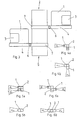
- the infrared detector includes two detector housings 1 with a window 3, behind which the detection optics are concealed, which have a limited detection range. Because the two detector housings 1 are arranged offset by 180 ° to one another, the total detection area is doubled.
- the two detector housings 1 are connected to a support 5 by means of tilting joints 6 via receiving parts 4. The tilt joints 6 enable the detector housing to be pivoted in a vertical plane.
- the carrier 5 is segmented, wherein individual segments 7 act as a pivot joint for the detector housing 1 and are held together by connecting elements 8.
- the swivel joints 7 on the one hand and the connecting elements 8 on the other hand are provided with corresponding grooves and recesses which enable a positive interlocking and ensure the rotational mobility of the swivel joints 7.
- a stop not shown here, serves to limit the horizontal pivoting of the detector housing to a maximum of 360 °. This measure prevents the connecting lines, which are not shown here and which have to be flexible anyway, are not over-tightened.
- the receiving parts 4 can be integrated into the detector housing 1. Any number of alternatives to the structure shown in FIG. 1 would of course be conceivable here. Even when choosing the joints, one is in no way bound to the embodiment proposed here, since the joints merely pivot the detector housing 1 horizontally and vertically should enable what is largely achievable with known ball joints, universal joints and other types of joints.
- the connection of the detector housing 1 to the carrier 5 can also be carried out in a variety of ways in such a way that the connecting lines are reliably guided.
- One of these options is to arrange a bellows in the joint area in which the cables are also routed, which makes the housing practically flexible and protects the internal parts. Such an arrangement is known for example from DE-GM 8 534 063.
- FIG. 3 shows an alternative to the embodiment according to FIG. 1, which makes it possible to use already existing detector housings 1 for the arrangement according to the invention without any significant change.
- the receiving parts 4 are designed as shells, which in turn are mechanically connected to the carrier 5 via a tilt joint 6 and a swivel joint 7.
- the shell shape of the receiving part 4 is designed so that one can use a detector housing 1 of the type already used. Because of their diverse but known design options in the drawing, not shown clamping or holding elements ensure that the detector housing 1 cannot fall out of the receiving part 4.
- the receiving part 4 is in turn designed in such a way that the tilting joint 6 enables the detector housing to be pivoted in a vertical plane and with the rotating joint 7 in a horizontal plane.
- the swivel joint 7 consists of an annular clamp which is guided in a corresponding groove in the carrier 5.
- the two detector housings 1 are offset from one another in stages so that their swivel path moved on different horizontal levels and thus no mutual disability arises.
- the detector arrangement according to the invention comprises a plurality of detectors, each of which represents an independent electronic switch, then an electrical combination can consist in the individual switches being parallel to one another and thus each switch having a corresponding consumer, preferably a lighting device can turn on.
- each detector housing 1 must not only contain an optical recording system, but also the electronics required for evaluating the optical signals.
- this can easily be done by accommodating the components for the common electronics, which in this case also form a common switch, in a central housing 2.
- part of the segmented carrier 5 will be used for this purpose, and preferably a fixed segment will be selected, since this considerably simplifies the mechanical structure.
- the requirements to be made here are best met by a module technology in which the detector housings 1 designed as modules in accordance with FIG. 3 can be inserted in the required number in corresponding receiving parts 4, and the electrical connection is also established in the process.
- the connection can be made via a cable which is provided with a plug at its free end, and the counterpart of the plug can be attached to the housing jacket of the central housing 2.
- the plug connection can also be carried out within the receiving part 4 if a plug-in device is installed in it, which engages in a form-fitting manner in a plug connection attached to it when the detector housing 1 is introduced.
- Figures 4 to 6 show some alternative applications that can be solved with the detector device according to the invention.
- the angles ⁇ 1 and ⁇ 2 are intended to identify detection angles which each extend in a horizontal plane, while the angles ⁇ 1 and ⁇ 2 are related to vertical planes.
- both the angle ⁇ and the angle ⁇ are shown smaller than they are in conventional devices. It has already been pointed out that known devices achieve a horizontal detection angle of up to 180 °. Nevertheless, an expansion of the respective detection angle can in principle be achieved with a plurality of optical pickups arranged in different detector housings 1. When the detectors act as an on-off switch, the overlap remains Detection angle is irrelevant, since the detector as a whole can no longer be switched on, so it does not matter which sensor the switching signal originates from, which therefore detects a fault.
- Figure 4 shows an arrangement with two detector housings 1 and a central housing 2 serving as a support 5, which are arranged at right angles to one another and which e.g. could be installed in a corner of vertically adjoining corridors.
- a central housing 2 serving as a support 5
- In the foreground is the goal to enlarge the horizontal angle ⁇ by the angle ⁇ 1 + ⁇ 2.
- the arrangement according to FIG. 5 is intended to enable the vertical recording angle ⁇ to be enlarged, which is achieved in that the two detector housings 1 are rotated vertically into one plane, but their horizontal orientation is different.
- Such arrangements are preferably used where a far area and a near area are to be detected.
- FIG. 6 shows an arrangement which corresponds to the example of FIGS. 1 to 3 and which, in turn, has the aim of expanding the winding ⁇ extending in the horizontal. Arranged in the middle of a very large room or a correspondingly long corridor, it enables an infrared source to be determined in both directions.
Landscapes
- Physics & Mathematics (AREA)
- General Physics & Mathematics (AREA)
- Photometry And Measurement Of Optical Pulse Characteristics (AREA)
- Push-Button Switches (AREA)
- Switches Operated By Changes In Physical Conditions (AREA)
- Geophysics And Detection Of Objects (AREA)
- Burglar Alarm Systems (AREA)
- Cookers (AREA)
Applications Claiming Priority (2)
| Application Number | Priority Date | Filing Date | Title |
|---|---|---|---|
| DE3744399 | 1987-12-29 | ||
| DE3744399A DE3744399C2 (de) | 1987-12-29 | 1987-12-29 | Strahlungsempfindlicher Schalter |
Publications (3)
| Publication Number | Publication Date |
|---|---|
| EP0323621A2 true EP0323621A2 (fr) | 1989-07-12 |
| EP0323621A3 EP0323621A3 (en) | 1990-05-16 |
| EP0323621B1 EP0323621B1 (fr) | 1995-02-22 |
Family
ID=6343781
Family Applications (1)
| Application Number | Title | Priority Date | Filing Date |
|---|---|---|---|
| EP88121616A Expired - Lifetime EP0323621B1 (fr) | 1987-12-29 | 1988-12-23 | Commutateur sensible aux radiations |
Country Status (3)
| Country | Link |
|---|---|
| EP (1) | EP0323621B1 (fr) |
| AT (1) | ATE118911T1 (fr) |
| DE (2) | DE3744399C2 (fr) |
Cited By (7)
| Publication number | Priority date | Publication date | Assignee | Title |
|---|---|---|---|---|
| US4840462A (en) * | 1987-03-17 | 1989-06-20 | U.S. Philips Corporation | Method of driving a ferroelectric liquid crystal display device and associated display device to achieve gray scale |
| EP0529716A1 (fr) * | 1991-08-23 | 1993-03-03 | Freddy Lucky Bellis | Ensemble de détection |
| DE19534564A1 (de) * | 1995-09-18 | 1997-03-20 | Andreas Toeteberg | Passives Infrarot-Alarmsystem für den Objektschutz |
| GB2346690A (en) * | 1999-01-26 | 2000-08-16 | Optex Co Ltd | Passive type infrared detector |
| EP1420377A3 (fr) * | 2002-11-12 | 2006-04-12 | Zancan Gianfranco & C. s.a.s. | Détecteur infrarouge, spécialement pour l'utilisation à l'extérieur |
| EP2393071A3 (fr) * | 2010-05-03 | 2012-01-11 | Georgios Chlapoutakis | Dispositif périphérique qui connecte des systèmes d'alarme de domicile qui sert de protection globale d'une ouverture au moyen de commutateurs magnétiques et de capteurs de mouvement |
| EP2722830A3 (fr) * | 2012-10-19 | 2014-09-17 | Optex Co., Ltd. | Dispositif de détection d'intrusion |
Families Citing this family (6)
| Publication number | Priority date | Publication date | Assignee | Title |
|---|---|---|---|---|
| DE4301490A1 (de) * | 1993-01-21 | 1994-07-28 | Insta Elektro Gmbh & Co Kg | Passivinfrarot-Gerätesystem |
| DE19520241A1 (de) * | 1995-06-02 | 1996-12-05 | Abb Patent Gmbh | Schaltvorrichtung, die eine automatische Betätigung eines Beleuchtungsschalters ermöglicht |
| DE19645184A1 (de) * | 1996-11-02 | 1998-05-07 | Abb Patent Gmbh | Schalteinrichtung für eine Treppenhausbeleuchtung |
| DE10033431A1 (de) * | 2000-07-12 | 2002-01-24 | Sick Ag | Sensor |
| DE10060170B4 (de) * | 2000-12-04 | 2011-06-16 | Insta Elektro Gmbh | Passiv-Infrarot-Bewegungsmelder |
| DE102020128092A1 (de) | 2020-10-26 | 2022-04-28 | Markus Giehl | Bewegungsmelder mit mehreren Bewegungssensoren |
Family Cites Families (6)
| Publication number | Priority date | Publication date | Assignee | Title |
|---|---|---|---|---|
| FR2492113A1 (fr) * | 1980-10-10 | 1982-04-16 | Voltam Ind | Module support de barrage de protection par rayonnement et barrage forme de tels modules |
| DE3381729D1 (de) * | 1983-01-05 | 1990-08-16 | Zueblin Marcel | Optisches bauelement zum umlenken optischer strahlen. |
| DE8532796U1 (de) * | 1985-11-21 | 1986-01-09 | Gebrüder Merten GmbH & Co KG, 5270 Gummersbach | Berührungsloser Schalter |
| DE8534063U1 (de) * | 1985-12-04 | 1986-01-16 | Gebrüder Merten GmbH & Co KG, 5270 Gummersbach | Berührungslos wirkender Schalter |
| DE3933796C1 (en) * | 1989-10-10 | 1991-05-08 | Paul Hochkoepper Gmbh & Co Kg, 5880 Luedenscheid, De | IR alarm with tiltable housing - maintaining reception plane at right angles to observation plane |
| DE4036342C1 (en) * | 1990-11-15 | 1992-03-26 | Messerschmitt-Boelkow-Blohm Gmbh, 8012 Ottobrunn, De | Passive IR monitoring system - comprises stack of IR detectors distributed on column at various angles to cover complete field without gaps |
-
1987
- 1987-12-29 DE DE3744399A patent/DE3744399C2/de not_active Expired - Fee Related
-
1988
- 1988-12-23 DE DE3853148T patent/DE3853148D1/de not_active Expired - Fee Related
- 1988-12-23 EP EP88121616A patent/EP0323621B1/fr not_active Expired - Lifetime
- 1988-12-23 AT AT88121616T patent/ATE118911T1/de not_active IP Right Cessation
Cited By (11)
| Publication number | Priority date | Publication date | Assignee | Title |
|---|---|---|---|---|
| US4840462A (en) * | 1987-03-17 | 1989-06-20 | U.S. Philips Corporation | Method of driving a ferroelectric liquid crystal display device and associated display device to achieve gray scale |
| EP0529716A1 (fr) * | 1991-08-23 | 1993-03-03 | Freddy Lucky Bellis | Ensemble de détection |
| US5332902A (en) * | 1991-08-23 | 1994-07-26 | Bellis Freddy L | Module detection unit including infrared detectors |
| DE19534564A1 (de) * | 1995-09-18 | 1997-03-20 | Andreas Toeteberg | Passives Infrarot-Alarmsystem für den Objektschutz |
| DE19534564C2 (de) * | 1995-09-18 | 1998-12-24 | Andreas Toeteberg | Verfahren zur Informationsweitergabe zwischen Alarmgeräten oder anderen Systemgeräten eines Alarmsystems |
| GB2346690A (en) * | 1999-01-26 | 2000-08-16 | Optex Co Ltd | Passive type infrared detector |
| US6414314B1 (en) | 1999-01-26 | 2002-07-02 | Optex Co., Ltd. | Passive-type infrared detector with elongated detection areas |
| GB2346690B (en) * | 1999-01-26 | 2003-10-29 | Optex Co Ltd | Passive-type infrared detector |
| EP1420377A3 (fr) * | 2002-11-12 | 2006-04-12 | Zancan Gianfranco & C. s.a.s. | Détecteur infrarouge, spécialement pour l'utilisation à l'extérieur |
| EP2393071A3 (fr) * | 2010-05-03 | 2012-01-11 | Georgios Chlapoutakis | Dispositif périphérique qui connecte des systèmes d'alarme de domicile qui sert de protection globale d'une ouverture au moyen de commutateurs magnétiques et de capteurs de mouvement |
| EP2722830A3 (fr) * | 2012-10-19 | 2014-09-17 | Optex Co., Ltd. | Dispositif de détection d'intrusion |
Also Published As
| Publication number | Publication date |
|---|---|
| DE3853148D1 (de) | 1995-03-30 |
| DE3744399A1 (de) | 1989-07-13 |
| EP0323621A3 (en) | 1990-05-16 |
| ATE118911T1 (de) | 1995-03-15 |
| DE3744399C2 (de) | 1997-03-13 |
| EP0323621B1 (fr) | 1995-02-22 |
Similar Documents
| Publication | Publication Date | Title |
|---|---|---|
| EP0323621B1 (fr) | Commutateur sensible aux radiations | |
| DE10013780C1 (de) | Video-Überwachungsgerät mit einer Dome-Kamera und einem Schutzgehäuse | |
| DE69704599T2 (de) | Infrarot-Bewegungsmelder | |
| DE69215648T2 (de) | Antennen- und Tunerkombination | |
| EP0020917B1 (fr) | Arrangement optique pour détecteur de mouvement infrarouge passif | |
| EP0652422A2 (fr) | Dispositif pour recevoir des rayons lumineux | |
| DE69403943T2 (de) | Steckeranordnung für photoelektrischen Sensor | |
| DE3910653C2 (de) | Passiv-Infrarot-Bewegungsmelder | |
| DE2748849A1 (de) | Ueberwachungseinrichtung mit fernsehkamera | |
| DE102015006437B3 (de) | Nivelliereinheit für Kameras oder Sensoren | |
| EP1291698B1 (fr) | Dispositif pour le positionnement d'éléments à l'intérieur de systèmes optiques | |
| EP0859345B1 (fr) | Boítier de protection pour appareils optiques avec dispositif de fixation à une surface | |
| DE69916118T2 (de) | Verbessertes system für geophysikalische datenerfassungs | |
| EP0668692A1 (fr) | Caméra vidéo protégée contre les radiations électromagnétiques | |
| DE19705404C2 (de) | Schutzgehäuse für optische Geräte mit einem Haltekörper zum Anbringen an einer Befestigungsfläche | |
| DE3735956C2 (fr) | ||
| EP0442338B1 (fr) | Dispositif de surveillance optique | |
| DE19603094C2 (de) | Einbaukamera | |
| DE8029809U1 (de) | Haltevorrichtung für elektrische Geräte, insbesondere für Einbruchdetektoren | |
| DE19615552C2 (de) | Überwachungseinrichtung | |
| DE60004724T2 (de) | Vorrichtung zur panoramischen Ansicht, insbesondere von öffentlichen Lokalen | |
| DE69508057T2 (de) | Anlage zur Überwachung und Verteidigung eines bestimmten Raumes | |
| EP0844595B1 (fr) | Dispositif de surveillance infrarouge | |
| EP1039427B1 (fr) | Détecteur d'incendie | |
| DE29620402U1 (de) | Bewegungsmelder |
Legal Events
| Date | Code | Title | Description |
|---|---|---|---|
| PUAI | Public reference made under article 153(3) epc to a published international application that has entered the european phase |
Free format text: ORIGINAL CODE: 0009012 |
|
| AK | Designated contracting states |
Kind code of ref document: A2 Designated state(s): AT BE CH DE FR GB LI NL |
|
| PUAL | Search report despatched |
Free format text: ORIGINAL CODE: 0009013 |
|
| AK | Designated contracting states |
Kind code of ref document: A3 Designated state(s): AT BE CH DE FR GB LI NL |
|
| 17P | Request for examination filed |
Effective date: 19900710 |
|
| 17Q | First examination report despatched |
Effective date: 19920720 |
|
| GRAA | (expected) grant |
Free format text: ORIGINAL CODE: 0009210 |
|
| AK | Designated contracting states |
Kind code of ref document: B1 Designated state(s): AT BE CH DE FR GB LI NL |
|
| REF | Corresponds to: |
Ref document number: 118911 Country of ref document: AT Date of ref document: 19950315 Kind code of ref document: T |
|
| REF | Corresponds to: |
Ref document number: 3853148 Country of ref document: DE Date of ref document: 19950330 |
|
| ET | Fr: translation filed | ||
| GBT | Gb: translation of ep patent filed (gb section 77(6)(a)/1977) |
Effective date: 19950317 |
|
| PLBE | No opposition filed within time limit |
Free format text: ORIGINAL CODE: 0009261 |
|
| STAA | Information on the status of an ep patent application or granted ep patent |
Free format text: STATUS: NO OPPOSITION FILED WITHIN TIME LIMIT |
|
| 26N | No opposition filed | ||
| PGFP | Annual fee paid to national office [announced via postgrant information from national office to epo] |
Ref country code: FR Payment date: 19980925 Year of fee payment: 11 |
|
| PGFP | Annual fee paid to national office [announced via postgrant information from national office to epo] |
Ref country code: GB Payment date: 19980928 Year of fee payment: 11 |
|
| PGFP | Annual fee paid to national office [announced via postgrant information from national office to epo] |
Ref country code: CH Payment date: 19981020 Year of fee payment: 11 |
|
| PGFP | Annual fee paid to national office [announced via postgrant information from national office to epo] |
Ref country code: BE Payment date: 19981109 Year of fee payment: 11 |
|
| PG25 | Lapsed in a contracting state [announced via postgrant information from national office to epo] |
Ref country code: GB Free format text: LAPSE BECAUSE OF NON-PAYMENT OF DUE FEES Effective date: 19991223 |
|
| PG25 | Lapsed in a contracting state [announced via postgrant information from national office to epo] |
Ref country code: LI Free format text: LAPSE BECAUSE OF NON-PAYMENT OF DUE FEES Effective date: 19991231 Ref country code: CH Free format text: LAPSE BECAUSE OF NON-PAYMENT OF DUE FEES Effective date: 19991231 Ref country code: BE Free format text: LAPSE BECAUSE OF NON-PAYMENT OF DUE FEES Effective date: 19991231 |
|
| BERE | Be: lapsed |
Owner name: ASEA BROWN BOVERI A.G. Effective date: 19991231 |
|
| GBPC | Gb: european patent ceased through non-payment of renewal fee |
Effective date: 19991223 |
|
| PG25 | Lapsed in a contracting state [announced via postgrant information from national office to epo] |
Ref country code: FR Free format text: LAPSE BECAUSE OF NON-PAYMENT OF DUE FEES Effective date: 20000831 |
|
| REG | Reference to a national code |
Ref country code: FR Ref legal event code: ST |
|
| PGFP | Annual fee paid to national office [announced via postgrant information from national office to epo] |
Ref country code: NL Payment date: 20001106 Year of fee payment: 13 Ref country code: DE Payment date: 20001106 Year of fee payment: 13 |
|
| PGFP | Annual fee paid to national office [announced via postgrant information from national office to epo] |
Ref country code: AT Payment date: 20001107 Year of fee payment: 13 |
|
| PG25 | Lapsed in a contracting state [announced via postgrant information from national office to epo] |
Ref country code: AT Free format text: LAPSE BECAUSE OF NON-PAYMENT OF DUE FEES Effective date: 20011223 |
|
| PG25 | Lapsed in a contracting state [announced via postgrant information from national office to epo] |
Ref country code: NL Free format text: LAPSE BECAUSE OF NON-PAYMENT OF DUE FEES Effective date: 20020701 |
|
| PG25 | Lapsed in a contracting state [announced via postgrant information from national office to epo] |
Ref country code: DE Free format text: LAPSE BECAUSE OF NON-PAYMENT OF DUE FEES Effective date: 20020702 |
|
| NLV4 | Nl: lapsed or anulled due to non-payment of the annual fee |
Effective date: 20020701 |