EP0323860A2 - Système d'entraînement et positionnement - Google Patents
Système d'entraînement et positionnement Download PDFInfo
- Publication number
- EP0323860A2 EP0323860A2 EP89102725A EP89102725A EP0323860A2 EP 0323860 A2 EP0323860 A2 EP 0323860A2 EP 89102725 A EP89102725 A EP 89102725A EP 89102725 A EP89102725 A EP 89102725A EP 0323860 A2 EP0323860 A2 EP 0323860A2
- Authority
- EP
- European Patent Office
- Prior art keywords
- rotor
- partial windings
- position sensors
- rotor position
- voltage supply
- Prior art date
- Legal status (The legal status is an assumption and is not a legal conclusion. Google has not performed a legal analysis and makes no representation as to the accuracy of the status listed.)
- Granted
Links
Images

Classifications
-
- H—ELECTRICITY
- H02—GENERATION; CONVERSION OR DISTRIBUTION OF ELECTRIC POWER
- H02P—CONTROL OR REGULATION OF ELECTRIC MOTORS, ELECTRIC GENERATORS OR DYNAMO-ELECTRIC CONVERTERS; CONTROLLING TRANSFORMERS, REACTORS OR CHOKE COILS
- H02P6/00—Arrangements for controlling synchronous motors or other dynamo-electric motors using electronic commutation dependent on the rotor position; Electronic commutators therefor
- H02P6/14—Electronic commutators
-
- H—ELECTRICITY
- H02—GENERATION; CONVERSION OR DISTRIBUTION OF ELECTRIC POWER
- H02K—DYNAMO-ELECTRIC MACHINES
- H02K29/00—Motors or generators having non-mechanical commutating devices, e.g. discharge tubes or semiconductor devices
- H02K29/06—Motors or generators having non-mechanical commutating devices, e.g. discharge tubes or semiconductor devices with position sensing devices
- H02K29/08—Motors or generators having non-mechanical commutating devices, e.g. discharge tubes or semiconductor devices with position sensing devices using magnetic effect devices, e.g. Hall-plates, magneto-resistors
Definitions
- the invention relates to a drive and positioning system consisting of a rotor equipped with permanent magnets and a stator having at least two partial windings, the partial windings being connected to an electronic voltage supply circuit controlled by rotor position sensors for current commutation.
- a drive motor of the type mentioned at the outset is shown in the Magnetic Technology brochure from 1978 under the name "Brushless DC Motors".
- This is a direct current drive motor intended for different areas of application, which has a permanent magnetic rotor and a laminated stator with a stator winding consisting of two partial windings.
- the current rotor position is determined in each case by correspondingly arranged rotor position sensors, which can be designed as Hall sensors.
- the electronic voltage supply circuit commutates the feed current of the two sub-coils supplied by two power amplifiers in dependence on the determined rotor position in such a way that a continuous rotary movement occurs.
- the prior art also includes a brushless DC motor in an ironless version of the stator, which is described in the publication A.R. Millner from MIT Lincoln Laboratory, Lexington, Massachusetts dated June 1978 "A high-speed highefficiency permanent magnetic motor-generator" was described.
- the rotor equipped with a number of sector-shaped permanent magnets induces in its rotational movement in the fixed stator winding signal voltages that are used to commutate the stator current in an electronic voltage supply circuit. Even in the case of this brushless motor, only dynamic commutation during the rotary movement, but no adjustment of a desired static setpoint position is possible.
- DE-AS 28 32 387 discloses a brushless DC motor with an axial air gap, which has permanent magnets magnetized in the axial direction on a rotor plate in conjunction with a rotor backplate.
- the stator consists of two disc-shaped star-shaped drive coils one above the other, which are arranged on a fixed magnetizable return plate. Two Hall generators form the rotary position detector. Because of the fixed magnetizable return plate, there is no iron-free stator; rather, magnetizable materials lie in the alternating magnetic field.
- DD-PS 34 431 describes a flat, slow-running drive motor for the direct drive of flywheels.
- the stator has several approximately trapezoidal flat coils. There are no rotor position sensors.
- An electronic switch can be used as the commutator, which controls the fixed coils in succession at a predetermined frequency. Alternatively, current commutation is effected via a collector in connection with slip and segment rings.
- the invention is based on the task of creating a drive and positioning system which is suitable for a wide range of applications, in particular also for use in low temperatures, and which enables low-loss regulation of any extremely stable, unlimited setpoint rotation angle.
- the drive system is intended to maintain each specified setpoint position with high accuracy, consume no energy in it and deliver the maximum torque even with slight deviations from the setpoint position, which can be a rest position or a position of movement.
- the drive system should also enable high speeds with low losses.
- the characteristic of the invention is seen in a drive and positioning system of the type mentioned at the outset that the output signals from at least two rotor position sensors associated with the first multiplier elements are fed into the electrical voltage supply circuit in the case of two partial windings and multiplied by signal values derived from the target rotation angle of the rotor and that the partial windings are connected to associated power amplifiers, the inputs of which are connected to second multipliers, which are fed with the output signals from two rotor position sensors and with further input signals, the further input signals being formed by summing elements from the output signals of the first multipliers are.
- An iron-free stator design of the drive system in conjunction with this electronic voltage supply and control circuit, results in exact rotor positioning in any desired setpoint angle of rotation ß. Even after taking a prescribed rest position, an exact adjustment of this setpoint position with high holding force is possible.
- the rotor behaves practically magnetically engaged during its rotational movement and in the regulated setpoint position, strong magnetic forces counteracting any deflection from the prescribed movement or detent position.
- With an iron-free construction extremely precise, low-loss control is possible, whereby the power consumption only depends on the setpoint deviation depends on.
- Rotor position sensors are sensors that generate signals dependent on the magnetic field. It is preferred to use rotor position sensors which determine both the size and the sign of the magnetic field and emit electrical output signals.
- Hall sensors in a known manner as rotor position sensors. This results in favorable input variables for the electrical voltage supply and control circuit.
- the number of rotor position sensors should advantageously be chosen such that in addition to the position determination required for commutation, an additional detection of the rotor position and thus an identification of the rotor movement process that can also be evaluated for the control circuit is possible.
- the required information can be obtained with a minimum number of two rotor position sensors, i.e. the number of sensors corresponds at least to the number of partial windings.
- the required signal values can also be determined with a number of sensors corresponding to the number of partial windings or with a smaller number of sensors.
- each rotor position sensor is angularly opposite the following one staggered.
- n denotes the number of pole pairs generated by the permanent magnets, which determine the air gap in which the partial windings of the stator lie.
- the angular displacement is (1 + 4m)
- the formation of the pole pairs opposite one another at the air gap can be produced in various ways, in particular by opposing disc-shaped permanent magnets or by pole shoes of an iron circle which contains one or more permanent magnets.
- four Hall sensors are used as rotation position sensors, each by the angle are staggered.
- a constant rotation of the rotor results, for example, in a sinusoidal shape of the field rotating with the pole pairs and field-proportional sinusoidal Hall sensor signals, the signals being shifted from one another by the angle II / 4.
- C means a numerical constant.
- the output signals of the four Hall sensors UH, U H2 , U H3 , U H4 are each fed to an assigned first multiplier and multiplied there by different signal values a, b, c and d, with a, b, c and d being functions of Target rotation angle ⁇ have the following sizes:
- the voltage supply circuit therefore delivers load currents, taking into account the sense of rotation, via the power amplifiers assigned to the corresponding partial windings.
- the magnetic field generated by the controlled partial windings tries to reduce the control deviation.
- Hall sensors instead of the Hall sensors, other suitable elements for position detection can also be used. Instead of scanning by means of rotor position sensors which are expediently integrated into the partial windings, another arrangement can optionally also be advantageous in which the rotor position signals are generated by an additional separate permanent magnet system or by other transmitter systems.
- the described electronic voltage supply circuit results in a perfect positioning of the drive unit, for example one connected to the carrier body, to drive component. Due to the magnetic detent in the guide movement of the rotor, even at low speeds and at a standstill, high forces can be transmitted to the component to be driven, which force it to be guided in the prescribed time function of the target rotation angle.
- Fig. 1 are in the upper part below the poles , the rotor two mutually offset partial windings I, II recognizable.
- the partial windings are advantageously designed to overlap in such a way that the free interior of the partial coils of one partial winding is almost completely filled by the web parts of the partial coils of the other partial winding. This is a favorable use of the free coil interior he aims.
- the Hall sensors H 1 , H 3 , H 2 , H 4 integrated in the partial windings are in the specified positions relative to the partial windings or their partial coils.
- the result is Hall sensor signals corresponding to the sinusoidal curve of the field strength as a function of the angle of rotation a.
- FIG. 2 shows the sinusoidal Hall sensor signals that occur as a time function in the dynamic case, namely when the rotor rotates at a constant speed.
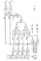
- a constant current source I c is provided for the constant current supply of the four Hall sensors H 1 , H 2 , H 3 , H 4 .
- the four Hall sensor signals UH, UH 2 UH, UH 4 are, after appropriate amplification by downstream amplifiers V 1 , V 2 , V 3 and V 4 , supplied to first multipliers ⁇ 1 , ⁇ 2 , ⁇ 3 , ⁇ 4 and with different signals a , b, c, d multiplied so that the signals a ⁇ U H 1 b ⁇ U H2 , c ⁇ U H3 3 and d ⁇ U H4 arise at the outputs of the multipliers.
- the signals a, b, c, d are functions of the specifiable soil angle ß and become sin from the functions ⁇ and cos ⁇ generated so that the following relationships apply:
- the control signal for the first power amplifier L i which is connected to the partial winding I, is formed from the product of U H1 and the correspondingly summed total signal from ⁇ 3 .
- the control signal for the second power amplifier L 2 for feeding the partial winding II is generated in the same way by the second multiplier ⁇ 6 as a product of the Hall sensor signal UH and the sum signal ⁇ 3 amplified by the control amplifier R.
- the predetermined setpoint angle ⁇ of the rotor rotation is set on a setpoint generator SW.
- the target angle ⁇ can be designed as a time function.
- voltages corresponding to a certain desired angle can be tapped on a voltage divider.
- ß G sin in a computing unit and cos formed and fed to a summing amplifier Eß and a differential amplifier ⁇ .
- the first multipliers ⁇ 1 , ⁇ 2 , ⁇ 3 , ⁇ 4 are the signals a, b, c, d given above.
- the output signals of the summing amplifier Eß and the differential amplifier ⁇ are cos and cos so c and d.
- the current local field profile is scanned relative to a partial coil of the tell windings with the four Hall sensors and compared with the theoretical target curve profile, obtained from the target angle ⁇ .
- the partial windings I, II are controlled by the voltage supply circuit in such a way that, in the state of equilibrium, the two curves correspond as closely as possible. In this way, the angle of rotation a of the rotor follows the respectively predetermined target angle ⁇ , which can be constant or a predefinable target function of time.
- any angle of rotation a of the rotor can be set with high resolution or precisely guided movements can be carried out, since the smallest deviation of the angle of rotation a from the current target angle ß immediately gives the maximum Torque for tracking is generated.
- the rotor is thus always in an electrodynamically locked state, and the position of the locking position can be set and shifted electronically.
- the detent position can also run continuously at constant speed, which means that arbitrarily low speeds can be generated with full torque.
- This electro-dynamic engagement caused by the special iron-free structure of the sub-coils of the drive system in connection with the special power supply circuit exceeds the mechanical engagement in terms of accuracy, reproducibility and service life. Since the rotor has no preferred mechanical zero position, electrical power is essentially only consumed when deflecting forces act from the desired position.
- the absolute rotor position is clear at first.
- the drive disengages and can be distributed in another of the possible circumferences Engage rest positions.
- the drive system can be operated like any other drive by external position feedback in normal servo function and can also be converted to an uncontrolled motor function. The combination with other analog or digital encoders is possible.
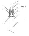
- Fig. 4 shows a possible design of the drive system.
- a coil-shaped ferromagnetic carrier body 1 of the rotor is provided, which carries two washer parts 2, 3, on the inner surfaces of which permanent magnets are arranged to form the pole pairs 4, 5.
- An iron-free, fixed, disk-shaped stator winding 6 with an I cross-section engages in the air gap formed by the pole pairs 4, 5 and the ring disks 2, 3.
- a locking pin 9 is used for the rotationally fixed fixing of the two ring disk parts 2, 3.
Landscapes
- Engineering & Computer Science (AREA)
- Power Engineering (AREA)
- Control Of Motors That Do Not Use Commutators (AREA)
- Brushless Motors (AREA)
- Vehicle Body Suspensions (AREA)
- Automatic Control Of Machine Tools (AREA)
- Automobile Manufacture Line, Endless Track Vehicle, Trailer (AREA)
Priority Applications (2)
| Application Number | Priority Date | Filing Date | Title |
|---|---|---|---|
| AT89102725T ATE65865T1 (de) | 1985-02-12 | 1986-01-30 | Antriebs- und positioniersystem. |
| EP89102725A EP0323860B1 (fr) | 1985-02-12 | 1986-01-30 | Système d'entraînement et positionnement |
Applications Claiming Priority (3)
| Application Number | Priority Date | Filing Date | Title |
|---|---|---|---|
| DE3504681 | 1985-02-12 | ||
| DE19853504681 DE3504681A1 (de) | 1985-02-12 | 1985-02-12 | Antriebs- und positioniersystem |
| EP89102725A EP0323860B1 (fr) | 1985-02-12 | 1986-01-30 | Système d'entraînement et positionnement |
Related Parent Applications (1)
| Application Number | Title | Priority Date | Filing Date |
|---|---|---|---|
| EP86101179.9 Division | 1986-01-30 |
Publications (3)
| Publication Number | Publication Date |
|---|---|
| EP0323860A2 true EP0323860A2 (fr) | 1989-07-12 |
| EP0323860A3 EP0323860A3 (en) | 1989-07-26 |
| EP0323860B1 EP0323860B1 (fr) | 1991-07-31 |
Family
ID=25829308
Family Applications (1)
| Application Number | Title | Priority Date | Filing Date |
|---|---|---|---|
| EP89102725A Expired - Lifetime EP0323860B1 (fr) | 1985-02-12 | 1986-01-30 | Système d'entraînement et positionnement |
Country Status (2)
| Country | Link |
|---|---|
| EP (1) | EP0323860B1 (fr) |
| AT (1) | ATE65865T1 (fr) |
Cited By (2)
| Publication number | Priority date | Publication date | Assignee | Title |
|---|---|---|---|---|
| EP0675590A1 (fr) * | 1994-03-30 | 1995-10-04 | SOLE S.p.A. | Moteur de commutation électronique |
| WO2011054329A1 (fr) * | 2009-11-09 | 2011-05-12 | Schaeffler Technologies Gmbh & Co. Kg | Procédé de régulation de glissement d'un embrayage à friction et actionneur d'embrayage correspondant |
Family Cites Families (4)
| Publication number | Priority date | Publication date | Assignee | Title |
|---|---|---|---|---|
| GB1596681A (en) * | 1977-01-19 | 1981-08-26 | Sony Corp | Drive circuits with speed control for brushless dc motors |
| GB2039095B (en) * | 1978-12-07 | 1982-11-24 | Hansen J S | Electric motors speed regulation |
| JPS57177293A (en) * | 1981-04-21 | 1982-10-30 | Victor Co Of Japan Ltd | Drive circuit for dc brushless motor |
| CH656266A5 (fr) * | 1982-09-22 | 1986-06-13 | Claude Gillieron | Dispositif pour la commande d'un moteur a courant continu. |
-
1986
- 1986-01-30 EP EP89102725A patent/EP0323860B1/fr not_active Expired - Lifetime
- 1986-01-30 AT AT89102725T patent/ATE65865T1/de not_active IP Right Cessation
Cited By (5)
| Publication number | Priority date | Publication date | Assignee | Title |
|---|---|---|---|---|
| EP0675590A1 (fr) * | 1994-03-30 | 1995-10-04 | SOLE S.p.A. | Moteur de commutation électronique |
| WO2011054329A1 (fr) * | 2009-11-09 | 2011-05-12 | Schaeffler Technologies Gmbh & Co. Kg | Procédé de régulation de glissement d'un embrayage à friction et actionneur d'embrayage correspondant |
| CN102549293A (zh) * | 2009-11-09 | 2012-07-04 | 舍弗勒技术股份两合公司 | 用于摩擦离合器的滑动调节的方法及其离合器致动器 |
| US9014935B2 (en) | 2009-11-09 | 2015-04-21 | Schaeffler Technologies AG & Co. KG | Method for the slip regulation of a friction clutch and clutch actuator therefor |
| CN102549293B (zh) * | 2009-11-09 | 2015-11-25 | 舍弗勒技术股份两合公司 | 用于摩擦离合器的滑动调节的方法及其离合器致动器 |
Also Published As
| Publication number | Publication date |
|---|---|
| EP0323860B1 (fr) | 1991-07-31 |
| ATE65865T1 (de) | 1991-08-15 |
| EP0323860A3 (en) | 1989-07-26 |
Similar Documents
| Publication | Publication Date | Title |
|---|---|---|
| EP0191366B1 (fr) | Système d'actionnement et positionnement | |
| DE2807834A1 (de) | Halleffekt-kodiergeraet fuer winkelstellungen von wellen | |
| EP0167803B1 (fr) | Moteur à courant continu triphasé sans collecteur | |
| DE69407250T2 (de) | Magnetisches rotierendes Gerät | |
| EP0228535A1 (fr) | Méthode et appareil pour la détermination de l'angle de flux d'une machine à induction et d'autre part pour le fonctionnement de la machine en orientation de position | |
| DE3838579C2 (fr) | ||
| DE102015106890A1 (de) | Steuerung zum Treiben eines Schrittmotors | |
| DE3120559A1 (de) | Reaktionsschneller servoantrieb | |
| DE4203433A1 (de) | Induktiv arbeitender stellungsdetektor fuer einen elektromotor | |
| DE69111889T2 (de) | Elektromagnetisches Antriebssystem. | |
| DE2343760B2 (de) | Anordnung zur Lagesteuerung eines elektromotorisch bewegten Gliedes | |
| EP0784378A2 (fr) | Procédé pour déterminer la position absolue du rotor de machines synchrones controllées par leur champ, ainsi qu'un dispositif pour mettre en oeuvre ce procédé | |
| DE1908579A1 (de) | Buersten- und lagerloser Drehfeldgeber | |
| WO1990007229A1 (fr) | Procede et dispositif pour la commande de convertisseurs electro-mecaniques | |
| DE1563741B2 (de) | Einrichtung zur laeuferstromregelung einer doppeltgespeisten drehstrommaschine | |
| DE69203886T2 (de) | Winkelgeber, insbesondere für drehende Maschinen mit sehr hoher Laufgeschwindigkeit. | |
| DE2755544A1 (de) | Antriebsvorrichtung fuer einen drehteller | |
| EP0323860B1 (fr) | Système d'entraînement et positionnement | |
| DE2833028A1 (de) | Geraet zur speisung, regelung und steuerung von elektrischen gleichstrommaschinen mit elektronischer kommutierung | |
| DE2914495A1 (de) | Kreisellaeuferantrieb | |
| DE3240809C2 (de) | Magnetlager | |
| DE2628616A1 (de) | Halleffekt-drehmeldersystem | |
| DE3300990C2 (fr) | ||
| DE1025504B (de) | Einrichtung, die auf einer Produktbildung unter Aunsutzung eines Effektes beruht, der an einem stromdurchflosenen mgnetisch steuerbaren Widerstandskoerper auftritt | |
| DE2725502C2 (de) | Anordnung zur Drehzahlerfassung und vorzugsweise Drehzahlregelung |
Legal Events
| Date | Code | Title | Description |
|---|---|---|---|
| PUAI | Public reference made under article 153(3) epc to a published international application that has entered the european phase |
Free format text: ORIGINAL CODE: 0009012 |
|
| PUAL | Search report despatched |
Free format text: ORIGINAL CODE: 0009013 |
|
| AC | Divisional application: reference to earlier application |
Ref document number: 191366 Country of ref document: EP |
|
| AK | Designated contracting states |
Kind code of ref document: A2 Designated state(s): AT BE CH DE FR GB IT LI NL SE |
|
| AK | Designated contracting states |
Kind code of ref document: A3 Designated state(s): AT BE CH DE FR GB IT LI NL SE |
|
| 17P | Request for examination filed |
Effective date: 19890708 |
|
| RAP1 | Party data changed (applicant data changed or rights of an application transferred) |
Owner name: DEUTSCHE FORSCHUNGSANSTALT FUER LUFT- UND RAUMFAHR |
|
| RAP1 | Party data changed (applicant data changed or rights of an application transferred) |
Owner name: DEUTSCHE FORSCHUNGSANSTALT FUER LUFT- UND RAUMFAHR |
|
| 17Q | First examination report despatched |
Effective date: 19900711 |
|
| GRAA | (expected) grant |
Free format text: ORIGINAL CODE: 0009210 |
|
| AC | Divisional application: reference to earlier application |
Ref document number: 191366 Country of ref document: EP |
|
| AK | Designated contracting states |
Kind code of ref document: B1 Designated state(s): AT BE CH DE FR GB IT LI NL SE |
|
| REF | Corresponds to: |
Ref document number: 65865 Country of ref document: AT Date of ref document: 19910815 Kind code of ref document: T |
|
| GBT | Gb: translation of ep patent filed (gb section 77(6)(a)/1977) | ||
| ET | Fr: translation filed | ||
| REF | Corresponds to: |
Ref document number: 3680674 Country of ref document: DE Date of ref document: 19910905 |
|
| ITF | It: translation for a ep patent filed | ||
| PLBE | No opposition filed within time limit |
Free format text: ORIGINAL CODE: 0009261 |
|
| STAA | Information on the status of an ep patent application or granted ep patent |
Free format text: STATUS: NO OPPOSITION FILED WITHIN TIME LIMIT |
|
| 26N | No opposition filed | ||
| PGFP | Annual fee paid to national office [announced via postgrant information from national office to epo] |
Ref country code: CH Payment date: 19921123 Year of fee payment: 8 |
|
| PGFP | Annual fee paid to national office [announced via postgrant information from national office to epo] |
Ref country code: AT Payment date: 19921126 Year of fee payment: 8 |
|
| PGFP | Annual fee paid to national office [announced via postgrant information from national office to epo] |
Ref country code: SE Payment date: 19921216 Year of fee payment: 8 |
|
| PGFP | Annual fee paid to national office [announced via postgrant information from national office to epo] |
Ref country code: BE Payment date: 19930128 Year of fee payment: 8 |
|
| PGFP | Annual fee paid to national office [announced via postgrant information from national office to epo] |
Ref country code: NL Payment date: 19930131 Year of fee payment: 8 |
|
| PG25 | Lapsed in a contracting state [announced via postgrant information from national office to epo] |
Ref country code: AT Effective date: 19940130 |
|
| PG25 | Lapsed in a contracting state [announced via postgrant information from national office to epo] |
Ref country code: SE Effective date: 19940131 Ref country code: LI Effective date: 19940131 Ref country code: CH Effective date: 19940131 Ref country code: BE Effective date: 19940131 |
|
| BERE | Be: lapsed |
Owner name: DEUTSCHE FORSCHUNGSANSTALT FUR LUFT- UND RAUMFAHR Effective date: 19940131 |
|
| PG25 | Lapsed in a contracting state [announced via postgrant information from national office to epo] |
Ref country code: NL Effective date: 19940801 |
|
| NLV4 | Nl: lapsed or anulled due to non-payment of the annual fee | ||
| REG | Reference to a national code |
Ref country code: CH Ref legal event code: PL |
|
| PGFP | Annual fee paid to national office [announced via postgrant information from national office to epo] |
Ref country code: GB Payment date: 19950124 Year of fee payment: 10 |
|
| PGFP | Annual fee paid to national office [announced via postgrant information from national office to epo] |
Ref country code: FR Payment date: 19950125 Year of fee payment: 10 |
|
| EUG | Se: european patent has lapsed |
Ref document number: 89102725.2 Effective date: 19940810 |
|
| PG25 | Lapsed in a contracting state [announced via postgrant information from national office to epo] |
Ref country code: GB Effective date: 19960130 |
|
| GBPC | Gb: european patent ceased through non-payment of renewal fee |
Effective date: 19960130 |
|
| PG25 | Lapsed in a contracting state [announced via postgrant information from national office to epo] |
Ref country code: FR Effective date: 19960930 |
|
| REG | Reference to a national code |
Ref country code: FR Ref legal event code: ST |
|
| PGFP | Annual fee paid to national office [announced via postgrant information from national office to epo] |
Ref country code: DE Payment date: 19981210 Year of fee payment: 14 |
|
| PG25 | Lapsed in a contracting state [announced via postgrant information from national office to epo] |
Ref country code: DE Free format text: LAPSE BECAUSE OF NON-PAYMENT OF DUE FEES Effective date: 20000131 |
|
| PG25 | Lapsed in a contracting state [announced via postgrant information from national office to epo] |
Ref country code: IT Free format text: LAPSE BECAUSE OF NON-PAYMENT OF DUE FEES Effective date: 20050130 |