EP0228535A1 - Méthode et appareil pour la détermination de l'angle de flux d'une machine à induction et d'autre part pour le fonctionnement de la machine en orientation de position - Google Patents
Méthode et appareil pour la détermination de l'angle de flux d'une machine à induction et d'autre part pour le fonctionnement de la machine en orientation de position Download PDFInfo
- Publication number
- EP0228535A1 EP0228535A1 EP86115282A EP86115282A EP0228535A1 EP 0228535 A1 EP0228535 A1 EP 0228535A1 EP 86115282 A EP86115282 A EP 86115282A EP 86115282 A EP86115282 A EP 86115282A EP 0228535 A1 EP0228535 A1 EP 0228535A1
- Authority
- EP
- European Patent Office
- Prior art keywords
- vector
- stator
- frequency
- components
- current
- Prior art date
- Legal status (The legal status is an assumption and is not a legal conclusion. Google has not performed a legal analysis and makes no representation as to the accuracy of the status listed.)
- Ceased
Links
- 238000000034 method Methods 0.000 title claims description 31
- 230000006698 induction Effects 0.000 title claims description 6
- 230000004907 flux Effects 0.000 title description 10
- 239000013598 vector Substances 0.000 claims abstract description 248
- 238000004804 winding Methods 0.000 claims abstract description 53
- 230000001360 synchronised effect Effects 0.000 claims abstract description 20
- 230000001419 dependent effect Effects 0.000 claims description 8
- 238000012937 correction Methods 0.000 claims description 5
- 238000009499 grossing Methods 0.000 claims description 5
- 230000001105 regulatory effect Effects 0.000 claims description 4
- 230000005284 excitation Effects 0.000 abstract description 9
- 230000008859 change Effects 0.000 description 7
- 230000010354 integration Effects 0.000 description 6
- 238000011156 evaluation Methods 0.000 description 5
- 230000010363 phase shift Effects 0.000 description 5
- 230000009466 transformation Effects 0.000 description 5
- 238000001514 detection method Methods 0.000 description 4
- 230000010355 oscillation Effects 0.000 description 4
- 238000006243 chemical reaction Methods 0.000 description 3
- 230000003111 delayed effect Effects 0.000 description 3
- 238000005259 measurement Methods 0.000 description 3
- 230000008569 process Effects 0.000 description 3
- 230000006978 adaptation Effects 0.000 description 2
- 230000008901 benefit Effects 0.000 description 2
- 230000033228 biological regulation Effects 0.000 description 2
- 230000015572 biosynthetic process Effects 0.000 description 2
- 238000004364 calculation method Methods 0.000 description 2
- 238000010276 construction Methods 0.000 description 2
- 230000008878 coupling Effects 0.000 description 2
- 238000010168 coupling process Methods 0.000 description 2
- 238000005859 coupling reaction Methods 0.000 description 2
- 238000013461 design Methods 0.000 description 2
- 238000010586 diagram Methods 0.000 description 2
- 230000001939 inductive effect Effects 0.000 description 2
- 230000005415 magnetization Effects 0.000 description 2
- 239000011159 matrix material Substances 0.000 description 2
- 238000000819 phase cycle Methods 0.000 description 2
- 238000012935 Averaging Methods 0.000 description 1
- 230000003044 adaptive effect Effects 0.000 description 1
- 238000004458 analytical method Methods 0.000 description 1
- 230000000903 blocking effect Effects 0.000 description 1
- 230000001276 controlling effect Effects 0.000 description 1
- 230000001808 coupling effect Effects 0.000 description 1
- 238000011161 development Methods 0.000 description 1
- 230000018109 developmental process Effects 0.000 description 1
- 230000000694 effects Effects 0.000 description 1
- 238000005516 engineering process Methods 0.000 description 1
- 238000002474 experimental method Methods 0.000 description 1
- 238000002955 isolation Methods 0.000 description 1
- 238000011017 operating method Methods 0.000 description 1
- 230000000704 physical effect Effects 0.000 description 1
- 238000010791 quenching Methods 0.000 description 1
- 230000000171 quenching effect Effects 0.000 description 1
- 230000009467 reduction Effects 0.000 description 1
- 230000000717 retained effect Effects 0.000 description 1
- 238000000844 transformation Methods 0.000 description 1
Images


Classifications
-
- H—ELECTRICITY
- H02—GENERATION; CONVERSION OR DISTRIBUTION OF ELECTRIC POWER
- H02P—CONTROL OR REGULATION OF ELECTRIC MOTORS, ELECTRIC GENERATORS OR DYNAMO-ELECTRIC CONVERTERS; CONTROLLING TRANSFORMERS, REACTORS OR CHOKE COILS
- H02P21/00—Arrangements or methods for the control of electric machines by vector control, e.g. by control of field orientation
- H02P21/34—Arrangements for starting
Definitions
- the invention relates to a method for determining the flow angle of a three-phase machine when starting up and a method for the position-oriented operation of a three-phase machine by means of a position encoder which defines the direction vector of a rotating reference system.
- the invention further relates to an apparatus for performing the method.
- a dynamic optimal control of a synchronous machine in which an encoder calculates the stator-related components of a model vector describing the flow from electrical quantities of the machine, the direction of which defines a direction vector pointing in the direction of the field axis.
- A e.g. A setpoint for the component of the stator current vector perpendicular to the field, as well as a setpoint for the component parallel to the field, which indicates the magnetization to be applied by the stator, determine a setpoint vector for the stator current of the machine, which is related to this direction vector, from which the Direction vector, a control vector is determined with which a converter is controlled and a corresponding stator current is impressed on the machine.
- a so-called "voltage model” is often used as the encoder, which calculates the flux as an integral of the EMF, ie as an integral of the voltage minus the ohmic and inductive voltage drops in the stator.
- the voltage model only delivers an imprecise signal at low speeds, with DC voltage components acting as measurement errors in the voltage measurements occur, and integration errors of the technical integrators lead to incorrect determinations. Therefore, field-oriented operation with a voltage model is only possible at higher frequencies.
- the integration constant must be set by specifying a start value for the integration of the EMF.
- the axis of the EMF vector can also be used in some cases as the direction vector, which is rotated by 90 ° in relation to the field axis in the stationary case.
- the integration can then be omitted, but here, too, it is usually not possible to operate the system at low speeds with sufficient precision. Rather, another way of detecting the direction vector is required.
- a so-called "current model” simulates the processes that lead to the formation of the river in the rotor from instantaneous values of current and rotor position.
- a mechanical encoder is required to determine the rotor position. This effort is made possible by an incremental encoder or another non-position-coded encoder such as reduced a pure tachometer, but then the rotor axis must be detected (“located") in a different way when the machine is at a standstill or running slowly. This location is often complex even with position-coded mechanical sensors.
- a reduction in the effort for the determination of the direction vector is desirable even if the operation of the synchronous machine is not exactly oriented to the field axis but to the rotor axis, without high dynamics.
- an approximate value for the armature reaction can be calculated from the setpoint values of the stator current in order to rotate the stator current vector relative to the rotor axis by a load-dependent angle setpoint value, which takes into account the angle between the field axis and the rotor axis. Then, however, only the determination of the field axis is also based on a determination of the rotor axis; the difficulties of locating the rotor at low speeds are not eliminated.
- the voltage model for determining the position of the flow vector is ruled out at low speeds, while the current model has the same problems associated with rotor location.
- a complex mechanical encoder often appears to be necessary.
- non-field-oriented controls such as a slip control or other characteristic control, go mostly from the rotor position as a direction vector for the control of the stator current and require a mechanical position encoder.
- the invention is largely independent of how the electrical supply to the machine is controlled.
- the intermediate circuit voltage can be impressed by a control voltage, whereby e.g. a regulating and control unit can convert a setpoint value for the stator current amplitude as a reference variable into the corresponding control signal for controlling the intermediate circuit voltage.
- a particular problem is the detection of the rotor position even when starting up a double-fed asynchronous machine.
- the rotor windings and the stator windings are connected in series and the stator current also flows through the rotor. This is done using slip rings, which also force a change in the phase sequence.
- the stator current vector and its position relative to the stator is therefore equal to the rotor current vector and its position relative to the rotor, the rotor rotating at twice the stator frequency.
- the position of the field vector is also recorded and vice versa. This results in a particularly simple controllability, especially when using field orientation.
- the motor develops a torque that cannot be predicted in terms of amount and sign and an uncontrolled movement of the rotor in one direction or the other must be expected.
- the object of the invention is to determine the position of the direction vector which is used in a field-oriented or rotor-oriented operation of a three-phase machine (asynchronous machine or synchronous machine) is required and given the position of the rotating field axis or rotor axis is largely determined by electrical means.
- a complex mechanical encoder can be dispensed with entirely.
- a high-frequency component is impressed on an electrical state variable of the stator winding system.
- the electrical state variables of the stator winding system mean the currents and voltages in the individual stator coils, and the axes of the coils, to which the high-frequency component is impressed, determine the direction of the impressed component. It turns out that e.g. With an impressed high-frequency current in one or more stator coils, high-frequency components also occur in the voltage of these coils and in the currents and voltages of the other coils, the amplitude of which depends on the difference angle between the flux axis and and the direction of the impressed component. Therefore, the amplitude of the high-frequency component is detected from a state signal which represents another state variable of the stator winding system; the directional angle sought is determined from the dependence of the detected amplitude on the predetermined direction of the impressed high-frequency component.
- This locating of the rotor angle or field angle according to the invention can advantageously be developed into a method for operating a rotating field machine by means of an electrical position sensor, the output signal of which defines the direction vector of a position-oriented reference system. If one understands the stator current vector and the stator voltage vector under the electrical status vectors of the machine stand, then in this operation a position-oriented target vector for one of the two electrical status vectors, an additional reference value for this status vector which is high-frequency compared to the rotation frequency of the reference system, and a control vector related to the stand is formed according to the signals of the position encoder.
- This control vector controls a converter which impresses the stator windings with the electrical state vector corresponding to the target vector and the additional target value.
- the high-frequency components are isolated from a signal representing the other of the two electrical state vectors, and the electrical transmitter forms the signals defining the direction vector from the envelopes of the high-frequency components.
- a corresponding device advantageously has a voltage measuring element or other means for detecting the stator voltages, a bandpass or high-pass filter for isolating high-frequency components of the stator voltages, an averager for forming the envelopes of the high-frequency components and means for determining the components of the direction vector from the envelopes. Furthermore, a control device is provided with an input for specifying a reference variable for the components of the stator current in a reference system dependent on the direction vector, with an additional setpoint generator for generating a high-frequency additional setpoint and with an output from which a control signal for the stator current can be tapped. A power converter then impresses a current corresponding to the control signal on the stand of the machine.
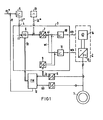
- the stator winding of a three-phase machine 1 is fed by a converter 2 with a stator current of variable amplitude and frequency, which is determined by a control device 3.
- a constant flow can be achieved by an excitation current control, not shown, wherein the excitation current can be calculated in a known manner from the active current setpoint, the setpoint for the power factor and the desired flow.
- il * is set proportionally to the desired flow.
- the target vector i * specified by field * by i1 * and i2 * must be transformed into the stator-related coordinate system and, in the case of a current control, also compared with the actual stator current value in order to arrive at a stator-oriented control vector and the amplitude and phase of the converter 2 supplying stator current.
- the coordinate transformation is first carried out, which corresponds to a rotation of the target vector i * by the flow angle fx.
- the vector rotator 6 thus supplies the stator-oriented current vector, which is converted into its polar coordinates by a coordinate converter 7, namely the current amplitude ai and the current phase wi.
- the three phase currents which correspond to the oblique-angled components of the actual stator current vector, are converted by a 3/2-coordinate converter 8 into the Cartesian components of a stator-related actual current vector is, from which a coordinate converter 9 supplies the corresponding actual values of amplitude and phase.
- An amplitude controller 10 and a phase controller 11 then supply the polar components of a control vector with which the amplitude ais and the phase wis of the converter output current are controlled.
- a transmitter 12 is required to form the direction vector fx.
- this often contains a flow computer which calculates the stator-related components FMa and FMb of a model vector FM describing the flow from electrical variables of the machine.
- the stator current vector is t picked off at the 2/3 converter and the vector us tapped at a corresponding 2/3 converter for the stator voltage serve as electrical quantities.
- the flux is given as an integral of the EMF, ie it can be calculated as if the parameter values r are sufficiently precise for the stator resistance and L for the leakage inductance
- an electrical encoder 12 based on the "voltage model” enables the field-oriented operation of the induction machine 1 only at higher frequencies. This is independent of the internal structure of the control device 3.
- the current actual vector is can be transformed into the field coordinate system using a vector rotator, the control deviation for the amplitudes of the vectors i * and is the amplitude ais of the control vector and the control deviation being converted into polar coordinates the angle is the corresponding control variable for the phase and frequency of the Converter supplies.
- the control deviation of the field-oriented or stator-oriented Cartesian components which then provide the Cartesian components of Ste L ervektors.
- the control vector also contains a correspondingly high-frequency component which is impressed on the stator current via the converter 2.
- the converter 2 is shown as a DC chopper 14 at the DC input of an inverter 15, it being possible to use the amplitude control variable (ais) to quickly adjust the current amplitude corresponding to the superimposed high-frequency component. If the additional vector iz * is a vector with a rapidly changing direction, the control variable wis can also be changed rapidly. A circumferential additional vector is, however, not absolutely necessary.
- the electrical encoder is fed by measuring elements for the stator voltage, the signals of which are optionally fed via the flow computer to a bandpass or high-pass filter for isolating high-frequency components in the measured voltages.
- the envelopes of the high-frequency components which can be acquired by an averager, are assigned to the components of the direction vector fx by suitable means. The structure of the electrical transmitter 12 required for this will be explained later.
- the voltage and current of a stator coil are referred to as "the two state variables of the coil", the state variables of the coils as “state variables of the stator winding system” and stator current vector and stator voltage vector as “state vectors of the stator” " designated.
- the invention is based on the observation that a high-frequency component of one electrical state variable which is impressed into one of the stator coils induces a high-frequency component of the other state variable of the same coil and high-frequency components of the state variables of the other coils.
- the high-frequency components depend on the position of the rotor or field axis.
- stator windings are inductively coupled to one another due to their geometric arrangement, in which they overlap one another in their edge regions.
- (USTz) corresponds to the other component of the voltage vector.
- Position-dependent envelopes of high-frequency components are also obtained if high-frequency voltages are impressed into the one coil instead of the current iz.
- the stator windings If there is no star point of the stator windings or if the star point is not connected, the high flows through frequency current iz always several windings and there are slightly different conditions. But even then, the position of the field angle of a permanently excited synchronous machine can be determined from the voltages, in particular from the envelope curves of the high-frequency components in the Cartesian components of the voltage vector. This also applies to asynchronous machines whose rotor winding is generally rotationally symmetrical and whose flow is induced by the stator current.
- stator windings are coupled to one another via effective rotor inductances which depend on the relative position between the rotor and the stator.
- the stator currents themselves, even in the field winding, cause currents which flow in the direction of the rotor axis and which additionally have a coupling effect on the stator windings.
- envelopes of the high-frequency stator voltage components are then assigned to the rotor axis, not the field axis, depending on the operating state and design of the machine.
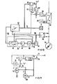
- the start of a three-phase machine 1 is considered as the first application of the method in FIG. 5, the converter 2 of which is controlled by a control and regulating device 3 as a function of the rotor position and whose speed n is detected by a simple speed sensor 50 with a downstream integrator 51 and function transmitters 52 for forming the components cos (fn.dt), sin (Jn.dt) of the direction vector px for the rotor position.
- the integrator 51 is initially set to any random value pxo, the converter is also started with a correspondingly random direction of its output current.
- the additional setpoint generator 13 (setpoint iz * ) impresses the high-frequency current iz in this random direction pxo and the voltages UR, US, UT measured at the machine terminals, which are converted by the 3/2 converter 9 into the components of the voltage vector u , consist practically only of high-frequency components according to any position on the abscissa in FIG. 3.
- These high-frequency components are filtered in a filter 53 by constant components, e.g. isolated from the DC voltage errors of the voltage measuring elements and an averager 62, the construction of which will be explained later, assigns the envelope of these high-frequency components to the sought-after components of the direction vector.
- the integrator output signal px can now be set to the correct angle value.
- This is done by forming the deviation of a Cartesian component as a measure of the angular deviation of the integrator output signal from the actual directional angle at the comparison point 54 and connecting it to the integrator input at a point 55. This adjusts px until the angles are the same.
- the directional vector px which describes the rotor axis and the field axis at a standstill, is thus located in the synchronous machine. Since converter 2 was also started as a function of px, the direction of the impressed current vector is now also set to the value belonging to px. In the case of an asynchronous machine in which the field axis points in the direction of the stator current at standstill and the rotor axis only plays a secondary role, this process ultimately locates the current vector that occurs when the converter is started.
- the mechanical transmitter 50 can also be omitted entirely or replaced by an electrical transmitter that uses the voltages, in particular using a flow calculator.
- the voltage URz in the coil through which high-frequency current flows is only a little bit different Rotor position dependent (Fig. 3), but the other voltages (Fig. 4), in particular the chained voltage (ie the component of the voltage vector perpendicular to the current vector) _1 allows a better assignment of its envelope curve to the angle px within its periodicity. Therefore, if only the voltages are evaluated, then only the voltages on the windings on which the additional nominal value of the current has no effect are expediently used and each time the direction of current flow is switched in the converter, the detection or evaluation of the envelopes is also switched on.
- the envelopes FHa and FHb coincide with the fundamental oscillations of FMa and FMb, ie they are equivalent to the Cartesian components of the direction vector fx.
- the envelopes correspond to the amplitudes of the high-frequency components FHa and FHb, averaged over a half period of the high frequency.
- these values FHa and FHb indicate the stand-oriented Cartesian components of a directional vector perpendicular to the field axis.
- the components fa and fb of the direction vector fx pointing in the field axis itself are assigned to the mean values FHb and FHa (FIG. 8).
- the advantage of forming the model field angle fx from the components FHa and FHb is that the assignment of FHa and FHb to the field vector fx shown in FIG. 8 is retained even at low rotational frequencies, even though the rotational frequency fundamental wave of the components FMa and FMb generally deviate from the correct assignment to field vector fx shown in FIG. 6 because of the calculation errors of the flow computer.
- the clock and control signals WR +, WR-,... WT- shown in FIG. 9 for the control of the inverter valves can be formed by corresponding limit indicators for the components fa and fb .
- You control the current vector so that it discontinuously assumes six stand-related angles wis, while its direction with respect to the field axis is always 90 ° ⁇ 30 ° el.
- a member 63 can also be connected in particular if a jerk-free switchover from the direction vector determined according to the method to the vector determined by the voltage model 60 is provided for higher speeds of the permanently excited synchronous machine 64.
- the direction vector fx formed in this way is broken down into its obliquely angled components by means of a 2/3 converter, which correspond to the projections of the rotor axis onto the three winding axes of the stator.
- An angle discriminator 65 ensures that the current in the stator winding is switched by 60 ° el after each rotor movement. This is done with the clock and control signals of FIG. 9, which correspond to the signal wis of FIG. 1.
- the amplitude of the stator current is supplied by a current controller 66, which compares the setpoint i * tapped at a speed controller 67 with the actual value is of the stator current amplitude.
- the actual value ff for the speed controller can be formed as the frequency of the direction vector fx by means of a differentiating circuit 68 and is the same as the rotor speed in the permanently excited machine.
- An additional setpoint value iz * in the form of an approximately sinusoidal oscillation of 250 Hz is now provided for the location by an additional setpoint generator 69 and is applied to the amplitude of the control current via the current controller 66.
- the angle discriminator 65 specifies a valve combination in the converter 64 'by the control signals WS + and WT-, in which the stator current specified by the amplitude control variable (ais) is fed into the winding S and is discharged via the winding T. This corresponds to an angle of the stator current vector with respect to the R winding axis of 90 ° .
- a stator current vector oscillating in the 250 Hz cycle is impressed in this direction. The machine is unable to follow this high frequency and remains at a standstill.
- the EMF induced by the permanent excitation should therefore remain constant and the flow computer should not show any change in the model vector FM which is at a randomly occurring initial value when switched on.
- the permanent excitation of the rotor causes a local saturation in the stator, which leads to different stator reactances with respect to the longitudinal and transverse axes and to different magnetic couplings of the individual phase windings.
- the voltage model 60 determines a model vector FM, which gains accuracy with increasing frequency and coincides with the direction of the actual field axis (rotor axis). Therefore, the operation of the synchronous machine according to the invention is provided here only for locating the field angle at a standstill and for operation at low speeds, while for higher speeds the direction vector fx is switched directly to the reference vector FM supplied by the voltage model.
- the component 63 is used, which additionally serves as a vector filter for determining the fundamental vibration of the vector FH.
- the components of a rotating vector are transformed into a rotating reference system by means of frequency-variable transformation elements, for which purpose the vector rotator 70 is provided according to FIG. 11, which has the components FHa and FHb of the vector FH is fed.
- a setpoint (eg the setpoint zero for a transformed vector component) defines a desired one Phase shift between the rotating vector and the abscissa of the rotating reference system, wherein a phase difference controller 71 forms the frequency of the frequency-variable transformation elements by regulating this phase shift and thus the rotating reference system synchronously tracks the rotating vector.
- the rotation frequency of the reference system therefore corresponds to the fundamental frequency of the vector and can be tapped at an output 72 as actual frequency value ff, the transformation elements themselves being formed by cos oscillator 73 as cos (Sff.dt) and sin (jff.dt) and on the one hand the angle input of the vector rotator 70 is fed back, on the other hand, are tapped as Cartesian components of the direction vector fx at an output 74.
- Such a vector filter also enables the operation to be switched from vector FH to model vector FM without any problems.
- the output signal of a threshold value sensor 75 switches the switch 76 at the actual value input of the controller 71 to the output of a vector rotator 77, which is fed by the model vector FM, at a predetermined limit speed. With this switchover, there are no discontinuities in the direction vector fx.
- the averager 62 of FIG. 10 contains a rectifier 80, which supplies the instantaneous amount of the high-frequency vibrations.
- Each instantaneous value is evaluated in a subsequent inverter circuit with a sign, which changes in each case after a zero crossing.
- the change of sign is preferably not determined directly from the zero crossing itself, but rather from the phase position of the high-frequency components with respect to the high-frequency additional setpoint.
- a smoothing element 81 is also connected in series, which is equipped with a short smoothing time that is approximately matched to the high frequency, and thus up to a small upper vibrations provides the instantaneous amplitude of the envelopes enclosing the high-frequency components.
- FIG. 12 The structure of a suitable inverter circuit 82 is shown in FIG. 12.
- the additional setpoint iz * itself can be used as the high-frequency reference signal.
- Swapping the polarity of the permanent magnets, i.e. A rotor axis rotated by 180 ° el, with the same adjustment of the delay times, means that the sign evaluation of FHa 'and FHb' must be exchanged.
- This can be done by an EXCLUSIVE-OR gate 93 with a negative output, which can be arranged between the detector 86 and the gates 89 and 90 and which causes a reversal of the sign evaluation by a sign reversal of the signal given at its second input 94.
- the components FHa and FHb obtained from FHa ', FHb' by the sign evaluation describe the vector FH perpendicular to the field axis and thus approximately to the model vector FM, so that the components FHb and FMa or FHa and FMb correspond and at the inputs of the Vector filter 63 can be assigned to each other.
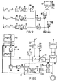
- FIG. 13 shows how this method can advantageously be inserted in the control structure shown in FIG. 1 of a device for field-oriented operation of an induction machine 1.
- a converter with an impressed intermediate circuit voltage is advantageously used as the converter, which contains a pulse-controlled inverter 100 on the machine side.
- Pulse inverters made up of switching transistors also allow high frequencies to be precisely controlled. But there is often a tension between them circular converter can be used with a machine-side thyristor converter with forced quenching.
- the field-oriented control device 101 is advantageously constructed such that the setpoint iz * of the additional setpoint generator 102 only acts on the amplitude of the control vector for the stator current. If, for example, a mechanical encoder is to be dispensed with at all, the speed controller 103 receives at its actual value input a frequency value ff derived from the direction vector fx.
- a frequency value ff derived from the direction vector fx.
- an EMF detector is sufficient. which is fed from the on 2/3 converters 104, 105 with the vectors u and i for voltage and current.
- the EMF detector 106 preferably supplies the integrand for an AC voltage integrator 107.
- Such an AC voltage integrator is described, for example, in German Offenlegungsschrift 28 33 593 and uses feedback signals to suppress DC voltage components. It has an adaptation input in order to adjust the passage of the feedback signals by means of the frequency of its input signals (here: the frequency ff) in such a way that a frequency-independent phase shift occurs in the AC voltage integration.
- the circuit diagram of the EMF detector 106 and the AC voltage integrator 107 also indicates that the model vector for the flow from the voltage vector is formed by subtracting the ohmic and inductive voltage drop.
- the vector FX at the output of the AC integrator 107 is inherently faulty at low frequencies due to the imperfection of the voltage model. However, these errors are compensated for by a correction vector DF, which is fed to a vector addition element 110 at the flow computer input and causes the model vector FX, the components of which simultaneously determine the direction fx of the direction vector fx, to track the vector FH formed according to the invention .
- the filter 108 and a circuit 109 constructed according to the averager 62 are connected to the output of the flow computer 106, 107.
- the correction vector DF is then formed by an adaptive control stage 111 from the control deviation FH-FX.
- a separate vector filter is usually not required here, since the vector rH only acts on the formation of FX via the integrator 107, which already represents smoothing.
- the function of the switch 76 contained in the vector filter of FIG. 11 can be implemented by a characteristic curve generator 113, which specifies the gain factor Vad for the control deviation in the correction controller 112 as a function of the operation, and continuously reduces the influence of the vector FH determined according to the invention, in particular with increasing speeds.
- the control stage 111 is thus adapted to the operating state and at higher speeds only the model vector determined in the flow computer 107 determines the direction angle.
- the control voltages at the input of the converter headset are a direct mathematical representation of the converter output current.
- the stator current vector thus corresponds to the control vector supplied by the output of the current regulator.
- the high-frequency additional setpoint for the current can be applied directly to the control input of the tax rate.
- the high-frequency components of the voltage vector can then be obtained directly from measured voltage values in the manner described in order to detect the position of the direction vector.
- a voltage-impressing converter for example a machine-side pulse-controlled inverter with a specified DC input voltage, for which setpoints for the three machine-side phase voltages are specified as control voltages, and the pulse pulses for the valves of the bridge arm pairs, each working on an AC voltage output, are formed by pulse width modulation.
- the control voltages are an image of the impressed stator voltage vector and, according to the invention, a high-frequency component of the stator voltage vector can be impressed directly at the control input of the tax rate by a high-frequency oscillating additional vector, and the direction vector can be determined from a measurement of the high-frequency components of the current that occur.
- a voltage converter for example, can be a direct converter or an intermediate circuit converter with a rectifier on the network side and a pulse-controlled inverter on the machine side.
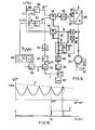
- the control voltages UR * , US * and UT * for the headset (not shown) of the converter are formed by means of a 2/3 coordinate converter 123 from the Cartesian, stator-related components of a control vector u *, which is practically identical to the stator voltage vector.
- control vector u * are taken from a control device with two controllers for the field-parallel component (magnetizing current) and the field-perpendicular component (active current) of the stator current vector, the control circuits for these two current components being decoupled from one another in a manner known to the person skilled in the art.
- This decoupling is symbolically represented in FIG. 14 in that the actual values il and i2 for magnetizing current and active current are taken from a vector rotator 124 for the stator current vector is obtained from current measured values and are compared at control comparison points 125 and 126 with the corresponding actual values il * and i2 * .
- the current regulators 127 and 128 form the setpoints ul * and u2 * for the field-oriented components of the stator voltage vector, which is converted by means of the vector rotator 129 into the stator-oriented components of the control vector u * .
- the direction of the field axis with respect to the stator is described by the field angle fx or the direction vector fx with the Cartesian, stand-related components cos fx and sin fx.
- this direction angle is reproduced with sufficient accuracy by the model vector FM for the flow, which is determined by a flow computer 60 by integrating the EMF vector (formed from the stator current vector is and the stator voltage vector us) or by another, as simple as possible transmitter.
- the integrator of the encoder 60 is at a random, arbitrary initial value.
- the following search method is used, with which the direction vector sought is determined before the operational start-up.
- the physical basics of this search procedure are shown again below.
- the vector equation generally applies between the stator current vector i and the stator voltage vector u where L represents an inductance matrix, the elements of which are functions of the operating variables, in particular the stator current vector and the position of the flux vector and the rotor. If a direction vector gx with the stator-related direction angle gx and an amount il (fl) is specified by the current feed for the stator current, and an amount il (fl) that oscillates with a high frequency fl without having a DC component, the rotor remains at rest and in a coordinate system related to gx the equation results
- the matrix elements Lll and L21 are functions of the difference angle px - gx and indicate how the voltages occurring at the stator coils or the components ul and u2 of the voltage vector depend on the derivative dil (fl) / dt of the impressed high-frequency current component.
- a similar equation also results for the case in which a high-frequency voltage is impressed in the direction gx, with which corresponding high-frequency components of the current or the derivative of the current are then coupled.
- the portion with the ohmic stator resistance R can in principle be eliminated by calculation or can be neglected here for further consideration. :
- a high-frequency generator 130 is provided for this purpose, which generates a high-frequency triangular voltage iz (fl) * by integrating a pulse frequency fl instead of a sinusoidal high frequency. If the ohmic component is neglected, the vector equation thus provides for the averaged parallel component of the position-oriented voltage vector
- Ll. 2 ⁇ fl.
- the component ul * of the control vector supplied by the current control and parallel to gx is practically proportional to the corresponding component of the actual voltage vector.
- the leakage inductances of the stator and rotor coils mainly determine the inductance, while in other positions the main and coupling inductances of the two winding systems also occur, so that minimum and maximum values are proportional to the voltage amplitude and the current amplitude result, which can differ by a factor of 20 - 50 depending on the design.
- This pronounced dependence of the inductances on the difference angle between the impressed high-frequency component and the rotor axis thus leads to an equally strong dependency for the detected amplitude
- the rotor angle can thus be determined by measuring or recording the amplitude as a function of the difference angle between the impressed high-frequency component iz * and the rotor axis.
- the continuous change in gx is ensured by an oscillator 133, the pulses of which in a counter 134 digitally integrated from the start value pg0 and converted into the components cos (2 ⁇ .f2.t), sin (2ir.f2.t) of a unit vector by means of function transmitters 135.
- the encoder 60 can then be set, for example, by forming the difference of this vector from the initially arbitrarily specified model vector fx and by adjusting the integrator of the encoder by the output signal of a zero point controller until the two vectors are equal.
- the angle fx of the direction vector fx tracks the angle 2 ⁇ .f2 with a slight delay, as long as the switch 137 at the input of the counter 134 is closed. Now when the maximum value of
- ul If switch 137 is open, the correct rotor position is located on the one hand, and encoder 60 is set to the correct starting value fx px on the other hand.
- the maximum inductance Lmax can advantageously first be predefined a variable A> Lmax, which is slowly and steadily reduced by means of an integrator 138, as shown in FIG. 15.
- the amplitude exceeds ul * for the first time the value A and a corresponding threshold value detector 139 triggers a signal C to open the switch 137.
- Appropriate input devices for example a flow controller and a speed controller, can now be enabled for the setpoints il * and 12 * for the further start-up.
- the method shown here in the case of an impressed high-frequency additional current component can, with appropriate adaptation of the control loops and the control rate, also be used for an impressed voltage component with detection of the current ripple generated.
- the decision criterion is then the current ripple in the position-oriented current actual value components: the direction vector is set correctly when the ripple of the parallel current actual component is minimal and the ripple of the vertical current actual component is maximum.
Landscapes
- Engineering & Computer Science (AREA)
- Power Engineering (AREA)
- Control Of Ac Motors In General (AREA)
- Motor And Converter Starters (AREA)
Applications Claiming Priority (2)
| Application Number | Priority Date | Filing Date | Title |
|---|---|---|---|
| DE3542941 | 1985-12-04 | ||
| DE3542941 | 1985-12-04 |
Publications (1)
| Publication Number | Publication Date |
|---|---|
| EP0228535A1 true EP0228535A1 (fr) | 1987-07-15 |
Family
ID=6287657
Family Applications (1)
| Application Number | Title | Priority Date | Filing Date |
|---|---|---|---|
| EP86115282A Ceased EP0228535A1 (fr) | 1985-12-04 | 1986-11-04 | Méthode et appareil pour la détermination de l'angle de flux d'une machine à induction et d'autre part pour le fonctionnement de la machine en orientation de position |
Country Status (5)
| Country | Link |
|---|---|
| US (1) | US4763058A (fr) |
| EP (1) | EP0228535A1 (fr) |
| JP (1) | JPS62138074A (fr) |
| AU (1) | AU580458B2 (fr) |
| NO (1) | NO864821L (fr) |
Cited By (13)
| Publication number | Priority date | Publication date | Assignee | Title |
|---|---|---|---|---|
| EP0317869A1 (fr) * | 1987-11-25 | 1989-05-31 | Siemens Aktiengesellschaft | Méthode pour simuler la valeur effective d'un angle de charge pour une machine à induction et circuit pour réaliser la méthode |
| EP0324146A1 (fr) * | 1988-01-14 | 1989-07-19 | Siemens Aktiengesellschaft | Méthode et appareil pour la détermination de la résistance de rotor d'une machine à induction |
| EP0380404A1 (fr) * | 1989-01-27 | 1990-08-01 | Thomson-Csf | Procédé et circuit d'asservissement de la vitesse d'un moteur à courant continu à la tension de commande du moteur |
| EP0660503A1 (fr) * | 1993-12-21 | 1995-06-28 | ABBPATENT GmbH | Méthode pour commander la valeur absolue de flux et de couple d'une machine à induction |
| WO1997008820A1 (fr) * | 1995-08-31 | 1997-03-06 | Siemens Aktiengesellschaft | Procede et dispositif de correction de la direction de flux d'un modele de flux d'un moteur a champ rotatif, commande sans capteur et par orientation de champ jusqu'a une frequence zero |
| EP0757432A3 (fr) * | 1995-08-04 | 1997-04-09 | Boeing Co | Démarrage d'une machine synchrone sans mesurer la vitesse ou la position du rotor |
| WO1997020382A1 (fr) * | 1995-11-27 | 1997-06-05 | Sieb & Meyer Elektronik Gmbh | Procede pour determiner la position initiale du rotor d'un moteur synchrone |
| DE19604701C1 (de) * | 1995-11-27 | 1997-06-12 | Sieb & Meyer Elektronik Gmbh | Verfahren zur Bestimmung der Anfangs-Rotorlage eines Synchronmotors |
| EP0784378A3 (fr) * | 1996-01-11 | 1997-08-06 | Siemens Aktiengesellschaft | Procédé pour déterminer la position absolue du rotor de machines synchrones controllées par leur champ, ainsi qu'un dispositif pour mettre en oeuvre ce procédé |
| EP0748039A3 (fr) * | 1995-06-08 | 1998-09-09 | Sony Corporation | Dispositif pour la détection de la position angulaire et dispositif moteur |
| AT408591B (de) * | 1989-04-06 | 2002-01-25 | Elin Ebg Traction Gmbh | Verfahren zur sensorlosen drehwinkelerfassung von dämpferlosen, vorzugsweise permanentmagneterregten, synchronmaschinen |
| EP2453571A1 (fr) | 2010-11-11 | 2012-05-16 | Celeroton AG | Convertisseur et procédé de commande d'une machine électrique à courant alternatif |
| RU2773000C1 (ru) * | 2020-06-22 | 2022-05-30 | Бомбардье Транспортейшн Гмбх | Способ регулирования многофазной электрической машины и система многофазной электрической машины для такого способа |
Families Citing this family (36)
| Publication number | Priority date | Publication date | Assignee | Title |
|---|---|---|---|---|
| US5224201A (en) * | 1988-03-31 | 1993-06-29 | Heidelberger Druckmaschinen Ag | Method and device for measuring rotary speed |
| FR2644950B1 (fr) * | 1989-03-21 | 1991-05-17 | Alsthom Gec | Systeme de commande vectorielle pour moteur electrique asynchrone a cage |
| US5051680A (en) * | 1989-12-08 | 1991-09-24 | Sundstrand Corporation | Simple starting sequence for variable reluctance motors without rotor position sensor |
| SE9000497L (sv) * | 1990-02-12 | 1991-08-13 | Ragnar Joensson | Foerfarande och apparat foer reglering av en asynkronmotor genom indirekt maetning av luftgapsspaenningen |
| JPH0433584A (ja) * | 1990-05-30 | 1992-02-04 | Toshiba Corp | すべり検出装置およびこれを用いた圧縮機の制御装置 |
| JP2820210B2 (ja) * | 1991-11-12 | 1998-11-05 | 三菱電機株式会社 | 同期機の等価回路不飽和インダクタンス測定方法 |
| JP3064671B2 (ja) * | 1992-04-27 | 2000-07-12 | 富士電機株式会社 | 電力変換装置の制御回路 |
| US5844397A (en) * | 1994-04-29 | 1998-12-01 | Reda Pump | Downhole pumping system with variable speed pulse width modulated inverter coupled to electrical motor via non-gap transformer |
| FI97797C (fi) * | 1994-09-30 | 1997-02-25 | Kone Oy | Menetelmä hissin käynnistämiseksi |
| AT405352B (de) * | 1995-05-30 | 1999-07-26 | Lst Laser & Strahl Gmbh | Verfahren zur läuferpositionsbestimmung für einen rotations- oder linear-motor und schaltungsanordnung zur durchführung dieses verfahrens |
| US5760359A (en) * | 1995-07-31 | 1998-06-02 | Matsushita Electric Industrial Co., Ltd. | Motor control apparatus equipped with a controller for controlling rotational position of motor |
| FR2746982B1 (fr) * | 1996-03-28 | 1998-05-07 | Schneider Electric Sa | Convertisseur de frequence pour moteur alternatif |
| DE19621046A1 (de) * | 1996-05-24 | 1997-11-27 | Skf Gmbh | Verfahren und Vorrichtung zur Messung des Abtriebsmomentes |
| DE19724946B4 (de) * | 1997-06-12 | 2005-09-15 | Siemens Ag | Verfahren und Vorrichtung zur Drehzahlregelung einer geberlosen, feldorientiert betriebenen Asynchronmaschine |
| AT406722B (de) * | 1998-01-30 | 2000-08-25 | Schroedl Manfred Dipl Ing Dr | Verfahren zur feldorientierten regelung einer mechanisch drehgeberlosen drehstrommaschine |
| US6169334B1 (en) | 1998-10-27 | 2001-01-02 | Capstone Turbine Corporation | Command and control system and method for multiple turbogenerators |
| US6489692B1 (en) | 1999-12-13 | 2002-12-03 | Capstone Turbine Corporation | Method and apparatus for controlling rotation of magnetic rotor |
| US6552509B2 (en) * | 2000-05-10 | 2003-04-22 | Gti Electroproject B.V. | Method and a device for sensorless estimating the relative angular position between the stator and rotor of a three-phase synchronous motor |
| DE10212751A1 (de) * | 2002-03-22 | 2003-10-02 | Bosch Gmbh Robert | Verfahren und Vorrichtung zur Ermittlung der Rotortemperatur bei einer PM-Synchronmaschine |
| US6809496B2 (en) * | 2002-09-16 | 2004-10-26 | Honeywell International Inc. | Position sensor emulator for a synchronous motor/generator |
| DE10311027A1 (de) * | 2003-03-13 | 2004-09-30 | Siemens Ag | Mess- und Simulationssystem für Werkzeug- oder Produktionsmaschinen |
| JP4397889B2 (ja) * | 2003-07-16 | 2010-01-13 | 三菱電機株式会社 | 同期電動機の磁極位置推定装置 |
| US7045986B2 (en) * | 2004-02-20 | 2006-05-16 | Honeywell International Inc. | Position sensing method and apparatus for synchronous motor generator system |
| JP4359546B2 (ja) * | 2004-09-06 | 2009-11-04 | 株式会社豊田中央研究所 | 交流モータの制御装置 |
| US7813904B2 (en) * | 2004-11-17 | 2010-10-12 | Toyota Technical Development Corporation | Method, apparatus, and computer readable medium based program for simulating an alternate current electric motor using a motor model |
| FR2933550B1 (fr) * | 2008-07-01 | 2012-10-12 | Schneider Toshiba Inverter Europe Sas | Procede de determination des inductances d'une machine synchrone a aimants permanents |
| JP5268615B2 (ja) * | 2008-12-15 | 2013-08-21 | キヤノン株式会社 | 電源装置および画像形成装置 |
| JP5396876B2 (ja) * | 2009-01-21 | 2014-01-22 | 株式会社安川電機 | 交流電動機の制御装置 |
| EP2276162B1 (fr) * | 2009-07-17 | 2012-10-03 | ebm-papst Mulfingen GmbH & Co. KG | Procédé et système de commande destinés au fonctionnement d'un moteur électrique sans balais |
| JP5199316B2 (ja) * | 2010-08-17 | 2013-05-15 | 東芝シュネデール・インバータ株式会社 | 電動機駆動装置 |
| DE102011086734B4 (de) * | 2011-11-21 | 2023-11-16 | Robert Bosch Gmbh | Verfahren zum Betreiben einer Energieversorgungseinheit für ein Bordnetz eines Kraftfahrzeugs |
| US20140285124A1 (en) * | 2013-03-12 | 2014-09-25 | Universiteit Gent | Control method and device therefor |
| US20150249419A1 (en) * | 2014-02-28 | 2015-09-03 | Kia Motors Corporation | System and method for controlling inverter |
| TWI672900B (zh) * | 2017-12-20 | 2019-09-21 | 財團法人工業技術研究院 | 電機驅動方法 |
| CN116131688B (zh) * | 2023-02-17 | 2024-03-19 | 江苏大学 | 一种五相永磁电机连续调制容错双随机低振噪控制方法 |
| GB2629674A (en) * | 2023-02-17 | 2024-11-06 | Univ Jiangsu | Continuous modulation fault-tolerant double-random low-vibration-noise control method for five-phase permanent magnet motor |
Citations (3)
| Publication number | Priority date | Publication date | Assignee | Title |
|---|---|---|---|---|
| DE2132178B2 (de) * | 1971-06-29 | 1976-08-12 | Siemens AG, 1000 Berlin und 8000 München | Verfahren und einrichtung zur steuerung oder regelung einer umrichtergespeisten, selbstgesteuerten synchronmaschine |
| DE3026348A1 (de) * | 1978-07-31 | 1982-02-04 | Siemens AG, 1000 Berlin und 8000 München | Schaltungsanordnung zur bildung eines elektrischen spannungssignals, das einer flusskomponente in einer drehfeldmaschine proportional ist |
| DE3347549A1 (de) * | 1983-12-30 | 1985-07-11 | Siemens AG, 1000 Berlin und 8000 München | Verfahren und vorrichtung zur bildung einer netzsynchronen schwingung |
Family Cites Families (4)
| Publication number | Priority date | Publication date | Assignee | Title |
|---|---|---|---|---|
| DE2353594C2 (de) * | 1973-10-25 | 1975-10-09 | Siemens Ag, 1000 Berlin Und 8000 Muenchen | Verfahren und Anordnung zur Ermittlung des Läuferwinkels einer Synchronmaschine |
| DE2833593C2 (de) * | 1978-07-31 | 1980-09-25 | Siemens Ag, 1000 Berlin Und 8000 Muenchen | Schaltungsanordnung zur Bildung eines elektrischen Spannungssignals, das einer Flußkomponente in einer Drehfeldmaschine proportional ist |
| DE3034251A1 (de) * | 1980-09-11 | 1982-04-15 | Siemens AG, 1000 Berlin und 8000 München | Verfahren und vorrichtung zum ermitteln des laeuferwiderstandes einer asynchronmaschine |
| NO851324L (no) * | 1984-05-18 | 1985-11-19 | Siemens Ag | Fremgangsmaate og anordning til aa bestemme en dreiefelt-maskins fluksvektor. |
-
1986
- 1986-11-04 EP EP86115282A patent/EP0228535A1/fr not_active Ceased
- 1986-12-01 NO NO864821A patent/NO864821L/no unknown
- 1986-12-03 JP JP61289728A patent/JPS62138074A/ja active Pending
- 1986-12-04 US US06/938,022 patent/US4763058A/en not_active Expired - Fee Related
- 1986-12-04 AU AU66088/86A patent/AU580458B2/en not_active Ceased
Patent Citations (3)
| Publication number | Priority date | Publication date | Assignee | Title |
|---|---|---|---|---|
| DE2132178B2 (de) * | 1971-06-29 | 1976-08-12 | Siemens AG, 1000 Berlin und 8000 München | Verfahren und einrichtung zur steuerung oder regelung einer umrichtergespeisten, selbstgesteuerten synchronmaschine |
| DE3026348A1 (de) * | 1978-07-31 | 1982-02-04 | Siemens AG, 1000 Berlin und 8000 München | Schaltungsanordnung zur bildung eines elektrischen spannungssignals, das einer flusskomponente in einer drehfeldmaschine proportional ist |
| DE3347549A1 (de) * | 1983-12-30 | 1985-07-11 | Siemens AG, 1000 Berlin und 8000 München | Verfahren und vorrichtung zur bildung einer netzsynchronen schwingung |
Non-Patent Citations (1)
| Title |
|---|
| REGELUNGSTECHNIK, Band 32, Nr. 1, 1984, Seiten 18-26, DE; R. GABRIEL: "Mikrorechnergeregelte Asynchronmaschine, ein Antrieb für hohe dynamische Anforderungen" * |
Cited By (18)
| Publication number | Priority date | Publication date | Assignee | Title |
|---|---|---|---|---|
| EP0317869A1 (fr) * | 1987-11-25 | 1989-05-31 | Siemens Aktiengesellschaft | Méthode pour simuler la valeur effective d'un angle de charge pour une machine à induction et circuit pour réaliser la méthode |
| EP0324146A1 (fr) * | 1988-01-14 | 1989-07-19 | Siemens Aktiengesellschaft | Méthode et appareil pour la détermination de la résistance de rotor d'une machine à induction |
| EP0380404A1 (fr) * | 1989-01-27 | 1990-08-01 | Thomson-Csf | Procédé et circuit d'asservissement de la vitesse d'un moteur à courant continu à la tension de commande du moteur |
| FR2642583A1 (fr) * | 1989-01-27 | 1990-08-03 | Thomson Csf | Procede et circuit d'asservissement de la vitesse d'un moteur a courant continu a la tension de commande du moteur |
| US5020126A (en) * | 1989-01-27 | 1991-05-28 | Thomson-Csf | Method and circuit for the automatic control of the speed of a DC motor by the control voltage of the motor |
| AT408591B (de) * | 1989-04-06 | 2002-01-25 | Elin Ebg Traction Gmbh | Verfahren zur sensorlosen drehwinkelerfassung von dämpferlosen, vorzugsweise permanentmagneterregten, synchronmaschinen |
| EP0660503A1 (fr) * | 1993-12-21 | 1995-06-28 | ABBPATENT GmbH | Méthode pour commander la valeur absolue de flux et de couple d'une machine à induction |
| EP0748039A3 (fr) * | 1995-06-08 | 1998-09-09 | Sony Corporation | Dispositif pour la détection de la position angulaire et dispositif moteur |
| US5877606A (en) * | 1995-08-04 | 1999-03-02 | The Boeing Company | Starting of synchronous machine without rotor position or speed measurement |
| EP0757432A3 (fr) * | 1995-08-04 | 1997-04-09 | Boeing Co | Démarrage d'une machine synchrone sans mesurer la vitesse ou la position du rotor |
| US5936377A (en) * | 1995-08-31 | 1999-08-10 | Siemens Aktiengesellschaft | Method and apparatus for correction of the flux direction of the modelled flux in a field-oriented rotating field-machine without any sensors, down to zero frequency |
| CN1056486C (zh) * | 1995-08-31 | 2000-09-13 | 西门子公司 | 用于修正一个无传感器的,磁场定向工作的感应式电机模型磁通的直至频率零的磁通方向的方法和装置 |
| WO1997008820A1 (fr) * | 1995-08-31 | 1997-03-06 | Siemens Aktiengesellschaft | Procede et dispositif de correction de la direction de flux d'un modele de flux d'un moteur a champ rotatif, commande sans capteur et par orientation de champ jusqu'a une frequence zero |
| DE19604701C1 (de) * | 1995-11-27 | 1997-06-12 | Sieb & Meyer Elektronik Gmbh | Verfahren zur Bestimmung der Anfangs-Rotorlage eines Synchronmotors |
| WO1997020382A1 (fr) * | 1995-11-27 | 1997-06-05 | Sieb & Meyer Elektronik Gmbh | Procede pour determiner la position initiale du rotor d'un moteur synchrone |
| EP0784378A3 (fr) * | 1996-01-11 | 1997-08-06 | Siemens Aktiengesellschaft | Procédé pour déterminer la position absolue du rotor de machines synchrones controllées par leur champ, ainsi qu'un dispositif pour mettre en oeuvre ce procédé |
| EP2453571A1 (fr) | 2010-11-11 | 2012-05-16 | Celeroton AG | Convertisseur et procédé de commande d'une machine électrique à courant alternatif |
| RU2773000C1 (ru) * | 2020-06-22 | 2022-05-30 | Бомбардье Транспортейшн Гмбх | Способ регулирования многофазной электрической машины и система многофазной электрической машины для такого способа |
Also Published As
| Publication number | Publication date |
|---|---|
| AU6608886A (en) | 1987-06-11 |
| NO864821L (no) | 1987-06-05 |
| NO864821D0 (no) | 1986-12-01 |
| US4763058A (en) | 1988-08-09 |
| AU580458B2 (en) | 1989-01-12 |
| JPS62138074A (ja) | 1987-06-20 |
Similar Documents
| Publication | Publication Date | Title |
|---|---|---|
| EP0228535A1 (fr) | Méthode et appareil pour la détermination de l'angle de flux d'une machine à induction et d'autre part pour le fonctionnement de la machine en orientation de position | |
| DE2341761C3 (de) | Schaltungsanordnung zum Betrieb eines fahrweggebundenen Triebfahrzeuges mit einem synchronen Linearmotor | |
| EP0847617B1 (fr) | Procede et dispositif de correction de la direction de flux d'un modele de flux d'un moteur a champ rotatif, commande sans capteur et par orientation de champ jusqu'a une frequence zero | |
| WO1992019038A1 (fr) | Procede et circuits pour determiner des variables d'etat electromagnetiques et mecaniques liees a la machine sur des generateurs a induction electrodynamiques alimentes par l'intermediaire de convertisseurs | |
| DE3715462A1 (de) | Verfahren und vorrichtung zur steuerung eines stromrichters mit selbsteinstellung von steuerparametern | |
| EP0043973A1 (fr) | Système d'entraînement d'une machine à champ tournant comportant une machine à champ tournant alimentée par l'intermédiaire d'un onduleur et une commande d'onduleur branchée à deux intégrateurs à tension alternative et au circuit d'un modèle de calcul | |
| DE2804297A1 (de) | Induktionsmotor-regelvorrichtung | |
| DE102015102565A1 (de) | Sensorloses Kommutierungsverfahren | |
| EP0127158A1 (fr) | Procédé et appareillage pour la détermination du vecteur de flux d'une machine à champ tournant d'après le courant stator et la tension stator et utilisation de ceux-ci | |
| DE2826332C3 (de) | Anordnung zur Drehzahlsteuerung einer über einen Gleichspannungs-Zwischenkreisumrichter gespeisten Wechselstrommaschine | |
| EP0161615B1 (fr) | Méthode et dispositif pour définir le vecteur de flux d'une machine à champ tournant | |
| EP0085871B1 (fr) | Procédé pour augmenter la vitesse maximale d'une machine synchrone pour un champ d'excitation et une tension aux bornes donnés et arrangement pour réaliser ce procédé | |
| DE4103933A1 (de) | Null-positionssensor | |
| DE10226974A1 (de) | Verfahren und Vorrichtung zur Bestimmung einer Rotorlage einer feldorientiert betriebenen Drehfeldmaschine ohne mechanischen Sensor | |
| EP0257396A1 (fr) | Procédé et dispositif pour le fonctionnement d'une machine à champ tournant alimentée par un convertisseur commandé | |
| DE3740712A1 (de) | Beschleunigunssteuervorrichtung | |
| EP3654524B1 (fr) | Procédé et unité de commande destinés au fonctionnement d'un moteur électrique | |
| DE3203974C2 (de) | Regelanordnung für einen mehrphasigen Wechselstrommotor | |
| DE19919752C1 (de) | Verfahren zum Zuschalten eines Umrichters an einen Asynchronmotor | |
| DE2240054A1 (de) | Induktiver stroemungsmesser | |
| DE102008045622A1 (de) | Verfahren zur Adaption einer Polradorientierung einer nicht linearen, geberlosen, permanenterregten Synchromaschine | |
| DE3525421A1 (de) | Verfahren und schaltungsanordnung zur herabsetzung der drehmoment-welligkeit eines stromrichtermotors im bereich kleiner drehzahlen | |
| DE19503658A1 (de) | Verfahren zur Bestimmung einer Größe zum stoßfreien Zuschalten eines drehzahlgeberlos betriebenen Asynchronmotors zu einem Wechselrichter | |
| DE102013223906B4 (de) | Verfahren zum Detektieren einer Drehlage eines Rotors einer Permanentmagnet-Synchronmaschine sowie Anordnung zum Durchführen dieses Verfahrens | |
| DE3727696A1 (de) | Verfahren und vorrichtung zum asynchronen motorischen hochlauf eines asynchrongenerators |
Legal Events
| Date | Code | Title | Description |
|---|---|---|---|
| PUAI | Public reference made under article 153(3) epc to a published international application that has entered the european phase |
Free format text: ORIGINAL CODE: 0009012 |
|
| AK | Designated contracting states |
Kind code of ref document: A1 Designated state(s): DE GB IT SE |
|
| 17P | Request for examination filed |
Effective date: 19870807 |
|
| 17Q | First examination report despatched |
Effective date: 19890922 |
|
| STAA | Information on the status of an ep patent application or granted ep patent |
Free format text: STATUS: THE APPLICATION HAS BEEN REFUSED |
|
| 18R | Application refused |
Effective date: 19901205 |
|
| RIN1 | Information on inventor provided before grant (corrected) |
Inventor name: HEINING, HANS-DIETER, DIPL.-ING. Inventor name: WICK, ALBERT, DR. |