EP0324069A2 - Fauteuil roulant électrique - Google Patents
Fauteuil roulant électrique Download PDFInfo
- Publication number
- EP0324069A2 EP0324069A2 EP88117759A EP88117759A EP0324069A2 EP 0324069 A2 EP0324069 A2 EP 0324069A2 EP 88117759 A EP88117759 A EP 88117759A EP 88117759 A EP88117759 A EP 88117759A EP 0324069 A2 EP0324069 A2 EP 0324069A2
- Authority
- EP
- European Patent Office
- Prior art keywords
- seating group
- chassis
- wheelchair according
- seating
- wheels
- Prior art date
- Legal status (The legal status is an assumption and is not a legal conclusion. Google has not performed a legal analysis and makes no representation as to the accuracy of the status listed.)
- Withdrawn
Links
Images

Classifications
-
- A—HUMAN NECESSITIES
- A61—MEDICAL OR VETERINARY SCIENCE; HYGIENE
- A61G—TRANSPORT, PERSONAL CONVEYANCES, OR ACCOMMODATION SPECIALLY ADAPTED FOR PATIENTS OR DISABLED PERSONS; OPERATING TABLES OR CHAIRS; CHAIRS FOR DENTISTRY; FUNERAL DEVICES
- A61G5/00—Chairs or personal conveyances specially adapted for patients or disabled persons, e.g. wheelchairs
- A61G5/04—Chairs or personal conveyances specially adapted for patients or disabled persons, e.g. wheelchairs motor-driven
- A61G5/041—Chairs or personal conveyances specially adapted for patients or disabled persons, e.g. wheelchairs motor-driven having a specific drive-type
- A61G5/042—Front wheel drive
-
- A—HUMAN NECESSITIES
- A61—MEDICAL OR VETERINARY SCIENCE; HYGIENE
- A61G—TRANSPORT, PERSONAL CONVEYANCES, OR ACCOMMODATION SPECIALLY ADAPTED FOR PATIENTS OR DISABLED PERSONS; OPERATING TABLES OR CHAIRS; CHAIRS FOR DENTISTRY; FUNERAL DEVICES
- A61G5/00—Chairs or personal conveyances specially adapted for patients or disabled persons, e.g. wheelchairs
- A61G5/04—Chairs or personal conveyances specially adapted for patients or disabled persons, e.g. wheelchairs motor-driven
- A61G5/041—Chairs or personal conveyances specially adapted for patients or disabled persons, e.g. wheelchairs motor-driven having a specific drive-type
- A61G5/045—Rear wheel drive
-
- A—HUMAN NECESSITIES
- A61—MEDICAL OR VETERINARY SCIENCE; HYGIENE
- A61G—TRANSPORT, PERSONAL CONVEYANCES, OR ACCOMMODATION SPECIALLY ADAPTED FOR PATIENTS OR DISABLED PERSONS; OPERATING TABLES OR CHAIRS; CHAIRS FOR DENTISTRY; FUNERAL DEVICES
- A61G5/00—Chairs or personal conveyances specially adapted for patients or disabled persons, e.g. wheelchairs
- A61G5/10—Parts, details or accessories
- A61G5/1051—Arrangements for steering
-
- A—HUMAN NECESSITIES
- A61—MEDICAL OR VETERINARY SCIENCE; HYGIENE
- A61G—TRANSPORT, PERSONAL CONVEYANCES, OR ACCOMMODATION SPECIALLY ADAPTED FOR PATIENTS OR DISABLED PERSONS; OPERATING TABLES OR CHAIRS; CHAIRS FOR DENTISTRY; FUNERAL DEVICES
- A61G5/00—Chairs or personal conveyances specially adapted for patients or disabled persons, e.g. wheelchairs
- A61G5/10—Parts, details or accessories
- A61G5/1078—Parts, details or accessories with shock absorbers or other suspension arrangements between wheels and frame
-
- A—HUMAN NECESSITIES
- A61—MEDICAL OR VETERINARY SCIENCE; HYGIENE
- A61G—TRANSPORT, PERSONAL CONVEYANCES, OR ACCOMMODATION SPECIALLY ADAPTED FOR PATIENTS OR DISABLED PERSONS; OPERATING TABLES OR CHAIRS; CHAIRS FOR DENTISTRY; FUNERAL DEVICES
- A61G2203/00—General characteristics of devices
- A61G2203/10—General characteristics of devices characterised by specific control means, e.g. for adjustment or steering
- A61G2203/14—Joysticks
-
- A—HUMAN NECESSITIES
- A61—MEDICAL OR VETERINARY SCIENCE; HYGIENE
- A61G—TRANSPORT, PERSONAL CONVEYANCES, OR ACCOMMODATION SPECIALLY ADAPTED FOR PATIENTS OR DISABLED PERSONS; OPERATING TABLES OR CHAIRS; CHAIRS FOR DENTISTRY; FUNERAL DEVICES
- A61G5/00—Chairs or personal conveyances specially adapted for patients or disabled persons, e.g. wheelchairs
- A61G5/10—Parts, details or accessories
- A61G5/1056—Arrangements for adjusting the seat
- A61G5/107—Arrangements for adjusting the seat positioning the whole seat forward or rearward
-
- A—HUMAN NECESSITIES
- A61—MEDICAL OR VETERINARY SCIENCE; HYGIENE
- A61G—TRANSPORT, PERSONAL CONVEYANCES, OR ACCOMMODATION SPECIALLY ADAPTED FOR PATIENTS OR DISABLED PERSONS; OPERATING TABLES OR CHAIRS; CHAIRS FOR DENTISTRY; FUNERAL DEVICES
- A61G5/00—Chairs or personal conveyances specially adapted for patients or disabled persons, e.g. wheelchairs
- A61G5/10—Parts, details or accessories
- A61G5/1056—Arrangements for adjusting the seat
- A61G5/1072—Arrangements for adjusting the seat rotating the whole seat around a vertical axis
-
- Y—GENERAL TAGGING OF NEW TECHNOLOGICAL DEVELOPMENTS; GENERAL TAGGING OF CROSS-SECTIONAL TECHNOLOGIES SPANNING OVER SEVERAL SECTIONS OF THE IPC; TECHNICAL SUBJECTS COVERED BY FORMER USPC CROSS-REFERENCE ART COLLECTIONS [XRACs] AND DIGESTS
- Y10—TECHNICAL SUBJECTS COVERED BY FORMER USPC
- Y10S—TECHNICAL SUBJECTS COVERED BY FORMER USPC CROSS-REFERENCE ART COLLECTIONS [XRACs] AND DIGESTS
- Y10S180/00—Motor vehicles
- Y10S180/907—Motorized wheelchairs
Definitions
- the invention relates to an electric wheelchair with a chassis which has larger drive wheels on a first axis and smaller swivel wheels on a second axis, with a seating group fastened to the chassis, each with a drive unit for the drive wheels and with an operating unit for controlling the drive unit.
- Electric wheelchairs are essentially divided into two categories according to their main intended use, the chassis being designed differently according to the respective intended use.
- first category large drive wheels are arranged in the rear area and small swivel wheels in the front area of the wheelchair, while wheelchairs that are primarily intended for use outside the home (second category) have large drive wheels in the front area and the small swivel wheels in the rear area.
- second category the center of gravity of the seating group or the unit of seating group and chassis is usually designed differently.
- the object of the invention is to provide an electric wheelchair of the type mentioned which can be used optimally for both operating modes, that is to say in the home and away from home, the changeover from one operating mode to the other being carried out simply and quickly.
- this object is achieved in that the seating group is pivotally mounted on the chassis about a vertical axis of rotation lying in the middle between the two wheel axes and can be locked in at least two end positions offset by 180 °, the seating direction in the end positions being perpendicular to the wheel axes stands and wherein the drive wheels serve either as front wheels or as rear wheels, and that the driving characteristic of the drive unit is also reversible according to the pivoting of the seating group.
- additional intermediate positions of the seating group can also be set, for example in an angular position of 90 ° to the longitudinal direction of the travel frame.
- a disabled person can be brought into a more favorable position transverse to the direction of travel for certain purposes, for example for getting in and out or for certain treatments.
- additional intermediate positions can be achieved at any angle if required.
- the height of the seating group is adjustable relative to the chassis.
- the chassis can, for example, have a vertical support column for the seating group, which is centrally located between the wheels and in which a rod-shaped pivot of the seating group is mounted.
- a locking device can be provided, which locks the chassis and the seating group against each other in the respectively desired angular positions.
- receiving bores can be provided on the chassis on a circle around the axis of rotation for a locking pin that is adjustably arranged on the seating group. This locking pin can be biased towards the receiving bores by spring force, so that it engages each time a locking position is reached.
- the movable part could also be attached to the chassis in the form of a locking pin or in any other shape, while the receptacles could be located in the rotating seating group for this purpose.
- the seating group rotatably arranged on the chassis is preferably also easily removable from the chassis cash and therefore interchangeable.
- different special constructions on seating groups can be interchanged with one another without any problems.
- Seating group is also held adjustable in the horizontal direction relative to the axis of rotation.
- a slide guide can be provided on which the seating group can be moved and locked in the desired position.
- the pivoting and the aforementioned horizontal adjustment of the seating group are usually carried out by hand.
- a servomotor for each of these swiveling or displacement movements.
- the drive unit can also be switched over manually using a switch, this switch being expediently arranged in the region of the operating device.
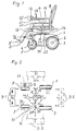
- the electric wheelchair shown in Fig. 1 has a chassis 1 with four wheel axles.
- the first two wheel axles 2 carry relatively large drive wheels 3, while two steering wheels which are small in comparison to the drive wheels are supported via a third and fourth axle 4, respectively.
- the big wheels are used to drive, the small wheels are used for steering.
- the suspension of the small wheels, i.e. the steering wheels, will be explained in more detail later.
- a seating group 6 is arranged substantially centrally between the wheel axles. It consists in a manner known per se of a seat element 7, a backrest 8 and a, for example adjustable, footrest 9, which in the example shown consists of two individual supports for each foot (see FIG. 2).
- armrests 11 are attached to each side of the seating group, an operating unit 12 with a control lever 13 being provided on the right armrest.
- the structure of the seating group corresponds to the conventional constructions.
- the seating group 6 In the position of the seating group 6 shown above the chassis 1 in FIG. 1, a wheelchair is shown for use in the house, since the large drive wheels are attached to the rear of the chassis and the swivel wheels in accordance with the seating position. For outdoor use of the wheelchair, however, it is more convenient to arrange the drive wheels at the front and the movable swivel wheels at the rear, as this makes it easier to overcome bumps and small obstacles.
- the seating group 6 is rotatably or pivotably arranged on the chassis 1.
- the chassis has a support column 14, over which the seating group 6 is mounted by means of a single rod-shaped pivot pin 15 with a vertical axis of rotation.
- the seating group can be rotated by 180 ° relative to the chassis in relation to the illustration in FIG. 1, so that the seating direction in FIG. 1 then points to the right, that is to say the drive wheels 3 in relation to the seating direction at the front and the swivel wheels 5 at the rear of the chassis lie.
- the operating device 12 is firmly coupled to the seating group, so that it is always accessible and operable in the same way for the disabled person sitting in a wheelchair.
- the seating group 6 is locked relative to the chassis 1 by means of a locking device 16.
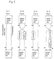
- FIG. 2 shows above the two pairs of wheels 3 and 5 from FIG. 1 shown in plan view different reachable seating positions in a schematic representation. Only the footrests 9 are shown, which, due to their arrangement relative to the wheels, illustrate the seat direction.
- the position shown in FIG. 1 is shown as position 1, with the footrests 9 lying in front of the small swivel wheels 5 in the drawing; to mark position 1, the footrests are 9-1 draws.
- An example of a possible configuration of the locking device 16 is shown in the middle between the four wheels. This locking device 16 is held on the seating group and has a locking pin 17 which is adjustable in the direction perpendicular to the axis of the support column 14 and is biased in this direction to the support column 14.
- a locking disk 18 is connected to the support column 14 and has a receptacle 19 for the free end of the locking pin 17 for each adjustable seating position. So if the seating group is rotated from the position shown in Fig. 1, the locking pin 17 shown in Fig. 2 is pulled out by means of a handle 20 (position 20 '), whereby the seating group 6 is unlocked from the support frame. To reverse the direction of travel, the seating group is now turned through 180 ° to position 2, so that the footrests assume the arrangement 9-2 shown in FIG. 2. The locking pin is mounted on the seating group and, after the rotation described, also assumes a position rotated by 180 °, which is not shown in FIG. 2. The locking pin 17 then snaps into the receptacle 19 due to its pretensioning (from above in the drawing).
- the control of the drive wheels must also be modified accordingly, since the changed directions of rotation for forward and reverse travel as well as the changed drive conditions for the steering must be taken into account for the drive wheels now in front.
- An additional modification is necessary if the seat direction is swiveled by 90 ° in relation to the direction of travel of the drive wheels.
- the electrical switchover of the drive units required for this can take place, for example, by actuating a switch 21 on the control unit.
- the signal for the respectively required setting of the drive units being generated by a sensor device 22 which is arranged in the border area between the chassis and the seating group and responds to a relative movement between the seating group on the one hand and the chassis on the other .
- Two sensor elements are required for binary scanning of four possible positions of the seating group. With eight positions, three sensors would be required, ie 2 n sensors each, where n is the number of possible positions.
- sensor elements all known components, such as microswitches, Hall elements, optocouples, inductive or capacitive proximity switches, etc., come into question. With a higher number of adjustable positions, incremental angle encoders of known design can also be used, the output variables of which can be evaluated electronically in order to ensure smooth transitions in the signal processing between the different sitting positions.
- FIG. 5 A diagram for an automatic adaptation of the speed and steering signals from the operating unit to the drive units is shown in FIG. 5. There is shown for each of the positions of the footrests shown in Fig. 2 (corresponding to the direction of the seating group) the corresponding implementation of the signals emitted by the control unit.
- the speed signal (GS) is sent unchanged from the control unit to the drive units, as is the steering signal indicating the desire to change direction.
- the speed signal (GS) is converted into a steering signal (LS) for the drive units (AE), the amplitude being reduced via a level adjustment (PE) .
- PE level adjustment
- a movement of the control lever on the control unit forwards for the drive wheels is converted into a steering signal to the right (forwards or backwards, depending on the additionally set speed signal).
- the steering signal (LS) generated by the control unit from the left or right pivoting of the control lever is converted into a speed signal (GS) for forward or Reverse drive of the drive wheels implemented.
- This signal is also reversed via an inverter (IN), so that a right control signal causes a reverse rotation and a left control signal causes the drive wheels 3 to rotate forward.
- the seat position is rotated by 180 °. It is sufficient to reverse only the speed signal (GS) with an inverter (IN), while the steering signal (LS) is also passed on to the drive units as a steering signal.
- the steering signal (LS) for the drive units is converted into a speed signal again, but without inversion.
- the speed signal (GS) is converted into a steering signal (LS) for the drive units (AE) via an inverter (IN) and additionally via a level adjustment (PS).
- the driving characteristics are adapted accordingly.
- a corresponding center of gravity adjustment can also be carried out for the rotating seating group for both directions of travel.
- a slide guide is provided in the seating group, which enables the entire seating group to be displaced horizontally with respect to the pivot pin 15.
- Individual parts of the seating group are indicated in Fig. 1 in a shifted position, for example an armrest 11 ', a footrest 9' and the shifted control unit 12 '.
- the slide guide itself is not shown in detail since such guide elements are familiar to the person skilled in the art.
- the swivel wheels 5 are suspended in a special way in order to obtain optimum driving characteristics for all purposes of the electric wheelchair, both indoors and outdoors.
- the two swivel wheels 5 are each freely pivotable on vertical axles 24 via wheel forks 23 and suspended via a balance beam system for different ground adjustments.
- the balance beam 25 is mounted on a horizontal pivot axis 26 and damped with respect to the chassis via spring elements 27. This makes it easy to absorb unevenness in the ground, especially outdoors.
- pneumatic-hydraulic damping elements 28 are additionally provided, which can either be fixed or adjusted by means of an adjusting screw 29. This measure improves the directional stability of the freely swiveling swivel wheels, particularly during fast journeys.
- Fig. 4 such steering damper 28 are shown schematically in plan view. From this schematic representation it can be seen that the steering damper is at an angle to the axis of the balance beam 25.
- the swivel wheels in the exemplary embodiment shown are freely pivoting, that is to say the change in direction of the wheelchair is brought about by different speeds of the two drive wheels.
- the swivel wheels turn automatically in the desired direction.
Landscapes
- Health & Medical Sciences (AREA)
- Life Sciences & Earth Sciences (AREA)
- Animal Behavior & Ethology (AREA)
- General Health & Medical Sciences (AREA)
- Public Health (AREA)
- Veterinary Medicine (AREA)
- Handcart (AREA)
- Seats For Vehicles (AREA)
- Automatic Cycles, And Cycles In General (AREA)
Applications Claiming Priority (4)
| Application Number | Priority Date | Filing Date | Title |
|---|---|---|---|
| DE3800648 | 1988-01-12 | ||
| DE3800648 | 1988-01-12 | ||
| DE3801874A DE3801874A1 (de) | 1988-01-12 | 1988-01-22 | Elektrorollstuhl |
| DE3801874 | 1988-01-22 |
Publications (2)
| Publication Number | Publication Date |
|---|---|
| EP0324069A2 true EP0324069A2 (fr) | 1989-07-19 |
| EP0324069A3 EP0324069A3 (fr) | 1990-01-10 |
Family
ID=25863885
Family Applications (1)
| Application Number | Title | Priority Date | Filing Date |
|---|---|---|---|
| EP88117759A Withdrawn EP0324069A3 (fr) | 1988-01-12 | 1988-10-25 | Fauteuil roulant électrique |
Country Status (6)
| Country | Link |
|---|---|
| US (1) | US4951766A (fr) |
| EP (1) | EP0324069A3 (fr) |
| CA (1) | CA1294523C (fr) |
| DE (1) | DE3801874A1 (fr) |
| DK (1) | DK10789A (fr) |
| NO (1) | NO885243L (fr) |
Cited By (4)
| Publication number | Priority date | Publication date | Assignee | Title |
|---|---|---|---|---|
| EP0911011A1 (fr) * | 1997-10-18 | 1999-04-28 | Sopur Medizintechnik GmbH | Fauteuil roulant à propulsion électrique |
| EP0908167A3 (fr) * | 1997-10-06 | 1999-12-08 | Invacare Corporation | Siège réversible pour fauteuil roulant avec entraínement de roue avant et roue arrière ayant un règlage angulaire en continu |
| WO2001089441A3 (fr) * | 2000-05-25 | 2002-04-11 | Movingpeople Net Internat B V | Chaise roulante |
| CN108938237A (zh) * | 2017-05-29 | 2018-12-07 | 丰田自动车株式会社 | 电动轮椅操作装置及其车辆操作方法 |
Families Citing this family (52)
| Publication number | Priority date | Publication date | Assignee | Title |
|---|---|---|---|---|
| US5137102A (en) * | 1986-08-25 | 1992-08-11 | Retec Pr, Inc. | Combination wheelchair and walker apparatus |
| US5096008A (en) * | 1990-09-24 | 1992-03-17 | Jericho Corporation | Stand-up wheelchair |
| US5356172A (en) * | 1991-07-23 | 1994-10-18 | Zvi Gilad Smolinsky | Sliding seat assembly for a propelled wheel chair |
| US5326063A (en) * | 1992-06-30 | 1994-07-05 | Quickie Designs Inc. | Swing-away joystick assembly |
| US5363933A (en) * | 1992-08-20 | 1994-11-15 | Industrial Technology Research Institute | Automated carrier |
| GB9313227D0 (en) * | 1993-06-26 | 1993-08-11 | Britax Restmor Ltd | Pushchair |
| US5518081A (en) * | 1993-07-15 | 1996-05-21 | Thibodeau; Bryan H. | All-terrain, all-weather wheelchair |
| US5401045A (en) * | 1993-11-18 | 1995-03-28 | Foerster; Stephen R. | Wheelchair with a barrier-free footrest |
| US5613738A (en) * | 1995-05-09 | 1997-03-25 | Britton; James E. | Restraining apparatus for a chair and method of making same |
| US6003624A (en) * | 1995-06-06 | 1999-12-21 | University Of Washington | Stabilizing wheeled passenger carrier capable of traversing stairs |
| US5732788A (en) * | 1995-09-14 | 1998-03-31 | Electric Mobility Corporation | Golf vehicle |
| US5884929A (en) * | 1996-09-10 | 1999-03-23 | Kincaid; David W. | Invalid transport |
| US6390213B1 (en) * | 1998-11-16 | 2002-05-21 | Joel N. Bleicher | Maneuverable self-propelled cart |
| US6290011B1 (en) * | 1999-11-01 | 2001-09-18 | Burke Mobility Products, Inc. | Front wheel/rear wheel drive convertible wheelchair |
| NO311555B1 (no) * | 2000-02-09 | 2001-12-10 | Stefan Solberg | Understell for elektrisk rullestol |
| US6554086B1 (en) | 2000-10-27 | 2003-04-29 | Invacare Corporation | Obstacle traversing wheelchair |
| TW466948U (en) * | 2001-04-10 | 2001-12-01 | Merits Health Products Co Ltd | Electric wheelchair with front and rear wheel drive |
| US6684969B1 (en) | 2001-04-26 | 2004-02-03 | Electric Mobility Corporation | Changeable personal mobility vehicle |
| DE10136369C2 (de) * | 2001-07-26 | 2003-05-28 | Alber Ulrich Gmbh & Co Kg | Kleinfahrzeug,insbesondere Rollstuhl |
| DE20121824U1 (de) * | 2001-07-26 | 2003-06-18 | Ulrich Alber GmbH & Co. KG, 72461 Albstadt | Kleinfahrzeug, insbesondere Rollstuhl |
| US7040429B2 (en) | 2001-10-10 | 2006-05-09 | Invacare Corporation | Wheelchair suspension |
| DE10246921B4 (de) * | 2002-02-08 | 2004-12-09 | Wacker, Christian | Motorisiertes Kleinfahrzeug für eine Einzelperson, insbesondere motorisiertes rollstuhlartiges Fahrzeug |
| DE10205461C1 (de) * | 2002-02-08 | 2003-10-09 | Wacker Christian | Motorisiertes Kleinfahrzeug für eine Einzelperson, insbesondere motorisiertes rollstuhlartiges Fahrzeug |
| US20070145711A1 (en) * | 2002-04-30 | 2007-06-28 | Mulhern James P | Rear wheel drive vehicle with ground-contacting anti-tip wheels |
| US11213441B2 (en) | 2002-10-25 | 2022-01-04 | Invacare Corporation | Suspension for wheeled vehicles |
| US7293801B2 (en) | 2003-08-18 | 2007-11-13 | Invacare Corporation | Self-stabilizing suspension for wheeled vehicles |
| TWM247195U (en) * | 2003-09-10 | 2004-10-21 | Univ Nat Chunghsing | Forward/backward movement control structure for electric wheelchair |
| US7121608B2 (en) * | 2004-09-23 | 2006-10-17 | Crown Equipment Corporation | Rotating and/or swiveling seat |
| DE102005020914B3 (de) * | 2005-05-04 | 2006-03-09 | Meyra Wilhelm Meyer Gmbh & Co. Kg | Elektrorollstuhl |
| US20070050096A1 (en) * | 2005-08-31 | 2007-03-01 | Invacare Corporation | Programmable actuator controller for power positioning seat or leg support of a wheelchair |
| NZ565933A (en) * | 2005-08-31 | 2011-05-27 | Invacare Corp | Adjustable mount for controller of power driven wheelchair |
| US7403844B2 (en) | 2005-08-31 | 2008-07-22 | Invacare Corporation | Method and apparatus for programming parameters of a power driven wheelchair for a plurality of drive settings |
| US7686319B1 (en) * | 2006-05-31 | 2010-03-30 | Robert M Fink | Double amputee conveyance |
| ATE493960T1 (de) | 2007-02-08 | 2011-01-15 | Invacare Corp | Rollstuhlaufhängung |
| DK2340800T3 (da) | 2007-02-14 | 2013-07-22 | Invacare Corp | Stabilitetsstyringssystem |
| US7748490B2 (en) * | 2007-06-26 | 2010-07-06 | University Of South Florida | Hands-free powered mobility device |
| EP3238682A3 (fr) | 2009-10-09 | 2018-01-10 | Invacare Corporation | Suspension de chaise roulante avec mouvement opposé du bras antibasculements |
| DE102009051118B4 (de) * | 2009-10-13 | 2014-04-30 | Otto Bock Mobility Solutions Gmbh | Elektrorollstuhl |
| NZ628837A (en) | 2012-02-15 | 2016-10-28 | Invacare Corp | Wheelchair suspension |
| CN102846063A (zh) * | 2012-09-11 | 2013-01-02 | 吴江市聚力机械有限公司 | 一种智能电动椅子 |
| DE102013000724B4 (de) | 2013-01-17 | 2018-06-21 | Bruno Walter | Geländegängiger Rollstuhl |
| US8814196B1 (en) * | 2013-02-19 | 2014-08-26 | Steven K. Poggenpohl | Shower transfer assistance scooter device |
| US9604668B2 (en) * | 2014-07-14 | 2017-03-28 | Caterpillar Forest Products Inc. | Control system for switching traction device inputs |
| CN104825287B (zh) * | 2015-05-22 | 2017-07-11 | 浙江全球跑电动轮椅有限公司 | 一种电动轮椅的椅座 |
| DE102016116371A1 (de) * | 2016-09-01 | 2018-03-01 | Fabio Giuseppe Gulino | Selbstbalancierende Transportvorrichtung, insbesondere Rollstuhl mit Dämpfung |
| EP3540127A4 (fr) * | 2016-10-20 | 2020-11-04 | Volvo Construction Equipment AB | Système de commande de déplacement de machine de construction |
| CN107049634A (zh) * | 2017-05-05 | 2017-08-18 | 常熟市平方轮椅有限公司 | 一种可爬坡电动轮椅车 |
| CN107049628A (zh) * | 2017-05-05 | 2017-08-18 | 常熟市平方轮椅有限公司 | 一种超轻智能轮椅车 |
| US11903887B2 (en) | 2020-02-25 | 2024-02-20 | Invacare Corporation | Wheelchair and suspension systems |
| US12303438B2 (en) * | 2020-11-13 | 2025-05-20 | Toyota Motor North America, Inc. | Multi-function mobility device |
| CN113367910B (zh) * | 2021-06-10 | 2022-11-22 | 深圳云净之信息技术有限公司 | 一种基于物联网可数据分析及安全监护的轮椅秤 |
| CN114376813B (zh) * | 2022-01-11 | 2024-04-26 | 南京康尼机电股份有限公司 | 电动轮椅以及控制方法 |
Family Cites Families (6)
| Publication number | Priority date | Publication date | Assignee | Title |
|---|---|---|---|---|
| AT4021B (fr) * | 1899-11-27 | 1901-05-10 | Victor Schweizer | |
| US2546765A (en) * | 1948-10-01 | 1951-03-27 | Tress L Mckinley | Invalid's bedchair |
| GB672175A (en) * | 1950-08-04 | 1952-05-14 | Herbert Austin Everest | Convertible wheel chair |
| US4351562A (en) * | 1980-07-17 | 1982-09-28 | Twitchell Brent L | Movable seat for a motorized transport chair |
| CA1166946A (fr) * | 1980-10-22 | 1984-05-08 | William R. Richardson | Appareil pour le transport des malades |
| SE431393B (sv) * | 1982-05-03 | 1984-02-06 | Permobil Ab | Styrbart, motordrivet hjulunderrede |
-
1988
- 1988-01-22 DE DE3801874A patent/DE3801874A1/de active Granted
- 1988-10-25 EP EP88117759A patent/EP0324069A3/fr not_active Withdrawn
- 1988-11-24 NO NO88885243A patent/NO885243L/no unknown
- 1988-11-25 CA CA000584206A patent/CA1294523C/fr not_active Expired - Lifetime
- 1988-12-19 US US07/286,522 patent/US4951766A/en not_active Expired - Fee Related
-
1989
- 1989-01-11 DK DK010789A patent/DK10789A/da not_active Application Discontinuation
Cited By (4)
| Publication number | Priority date | Publication date | Assignee | Title |
|---|---|---|---|---|
| EP0908167A3 (fr) * | 1997-10-06 | 1999-12-08 | Invacare Corporation | Siège réversible pour fauteuil roulant avec entraínement de roue avant et roue arrière ayant un règlage angulaire en continu |
| EP0911011A1 (fr) * | 1997-10-18 | 1999-04-28 | Sopur Medizintechnik GmbH | Fauteuil roulant à propulsion électrique |
| WO2001089441A3 (fr) * | 2000-05-25 | 2002-04-11 | Movingpeople Net Internat B V | Chaise roulante |
| CN108938237A (zh) * | 2017-05-29 | 2018-12-07 | 丰田自动车株式会社 | 电动轮椅操作装置及其车辆操作方法 |
Also Published As
| Publication number | Publication date |
|---|---|
| NO885243D0 (no) | 1988-11-24 |
| CA1294523C (fr) | 1992-01-21 |
| US4951766A (en) | 1990-08-28 |
| DE3801874C2 (fr) | 1992-06-17 |
| DK10789A (da) | 1989-07-13 |
| EP0324069A3 (fr) | 1990-01-10 |
| DK10789D0 (da) | 1989-01-11 |
| NO885243L (no) | 1989-07-13 |
| DE3801874A1 (de) | 1989-07-20 |
Similar Documents
| Publication | Publication Date | Title |
|---|---|---|
| DE3801874C2 (fr) | ||
| DE602004012744T2 (de) | Armlehne zur verwendung mit einem fahrzeugsitz | |
| DE3890037C2 (fr) | ||
| DE60222791T2 (de) | Verfahren zur programmierung und bedienung eines rollstuhls mit kipp- und rücklehnfunktionen | |
| EP0842844B1 (fr) | Siège de véhicule | |
| CH671332A5 (fr) | ||
| DE102020134877B4 (de) | Höhenverstellbarer Steuerhebelträger für einen Nutzfahrzeugsitz | |
| DE3228097A1 (de) | In alle richtungen fahrbarer rollstuhl | |
| DE4228849C1 (de) | Verstellbarer Fahrzeugsitz | |
| EP0324101A2 (fr) | Fauteuil roulant électrique | |
| EP3661803A1 (fr) | Véhicule à moteur pourvu d'au moins un siège de véhicule | |
| DE102022119627A1 (de) | Fahrzeugsitz | |
| EP1265577A1 (fr) | Fauteuil de traitement pour soins medicaux ou dentaires | |
| DE3643729C2 (de) | Sitzhalterung mit Sitzverstellung für einen Fahrzeugsitz | |
| EP0268960A2 (fr) | Fauteuil roulant pour malades | |
| DE69201691T2 (de) | Mobiles Röntgengerät. | |
| EP0364822A2 (fr) | Table avec cadre et surface de travail ainsi que dispositif de positionnement pour varier la hauteur et l'inclinaison de la surface de travail | |
| DE68902906T2 (de) | Sitz fuer schlepper mit umkehrbarer steuerungslage. | |
| DE3018686A1 (de) | Zahnaerztlicher patientenstuhl | |
| DE4311687A1 (de) | Radaufhängung für Fahrgestelle, insbesondere ein einspuriges Rollbrett | |
| DE3437962A1 (de) | Hoehenverstellbarer drehsitz fuer kraftfahrzeuge | |
| DE112020002199T5 (de) | Mobilität eines Röntgenbildgebungssystems | |
| DE3612891A1 (de) | Rollstuhl | |
| DE9012435U1 (de) | Medizinische Einrichtung mit einer Lagervorrichtung für einen Strahlensender oder einen Strahlenempfänger | |
| DE19828217C2 (de) | Kraftfahrzeugsitz, insbesondere Rücksitz |
Legal Events
| Date | Code | Title | Description |
|---|---|---|---|
| PUAI | Public reference made under article 153(3) epc to a published international application that has entered the european phase |
Free format text: ORIGINAL CODE: 0009012 |
|
| AK | Designated contracting states |
Kind code of ref document: A2 Designated state(s): AT CH DE FR LI NL SE |
|
| TCNL | Nl: translation of patent claims filed | ||
| EL | Fr: translation of claims filed | ||
| PUAL | Search report despatched |
Free format text: ORIGINAL CODE: 0009013 |
|
| AK | Designated contracting states |
Kind code of ref document: A3 Designated state(s): AT CH DE FR LI NL SE |
|
| 17P | Request for examination filed |
Effective date: 19900629 |
|
| 17Q | First examination report despatched |
Effective date: 19910904 |
|
| STAA | Information on the status of an ep patent application or granted ep patent |
Free format text: STATUS: THE APPLICATION IS DEEMED TO BE WITHDRAWN |
|
| 18D | Application deemed to be withdrawn |
Effective date: 19921107 |