EP0324176A2 - Dispositif d'éclairage fixé par serrage entre sol et plafond - Google Patents
Dispositif d'éclairage fixé par serrage entre sol et plafond Download PDFInfo
- Publication number
- EP0324176A2 EP0324176A2 EP88121831A EP88121831A EP0324176A2 EP 0324176 A2 EP0324176 A2 EP 0324176A2 EP 88121831 A EP88121831 A EP 88121831A EP 88121831 A EP88121831 A EP 88121831A EP 0324176 A2 EP0324176 A2 EP 0324176A2
- Authority
- EP
- European Patent Office
- Prior art keywords
- lamp
- busbars
- tubular
- guide rod
- luminaire
- Prior art date
- Legal status (The legal status is an assumption and is not a legal conclusion. Google has not performed a legal analysis and makes no representation as to the accuracy of the status listed.)
- Granted
Links
- 238000009434 installation Methods 0.000 claims abstract description 3
- 239000004020 conductor Substances 0.000 claims abstract 2
- 230000006835 compression Effects 0.000 claims description 4
- 238000007906 compression Methods 0.000 claims description 4
- 239000011810 insulating material Substances 0.000 claims 2
- 229910052736 halogen Inorganic materials 0.000 description 2
- 150000002367 halogens Chemical class 0.000 description 2
- 238000009413 insulation Methods 0.000 description 2
- 125000006850 spacer group Chemical group 0.000 description 2
- 238000004026 adhesive bonding Methods 0.000 description 1
- 230000004323 axial length Effects 0.000 description 1
- 239000002932 luster Substances 0.000 description 1
- 238000004519 manufacturing process Methods 0.000 description 1
Images

Classifications
-
- F—MECHANICAL ENGINEERING; LIGHTING; HEATING; WEAPONS; BLASTING
- F21—LIGHTING
- F21V—FUNCTIONAL FEATURES OR DETAILS OF LIGHTING DEVICES OR SYSTEMS THEREOF; STRUCTURAL COMBINATIONS OF LIGHTING DEVICES WITH OTHER ARTICLES, NOT OTHERWISE PROVIDED FOR
- F21V21/00—Supporting, suspending, or attaching arrangements for lighting devices; Hand grips
- F21V21/13—Spring-loaded poles fixed at both ends
-
- F—MECHANICAL ENGINEERING; LIGHTING; HEATING; WEAPONS; BLASTING
- F21—LIGHTING
- F21V—FUNCTIONAL FEATURES OR DETAILS OF LIGHTING DEVICES OR SYSTEMS THEREOF; STRUCTURAL COMBINATIONS OF LIGHTING DEVICES WITH OTHER ARTICLES, NOT OTHERWISE PROVIDED FOR
- F21V21/00—Supporting, suspending, or attaching arrangements for lighting devices; Hand grips
- F21V21/34—Supporting elements displaceable along a guiding element
- F21V21/35—Supporting elements displaceable along a guiding element with direct electrical contact between the supporting element and electric conductors running along the guiding element
Definitions
- the present invention relates to a lamp which can be set up by clamping between the floor and ceiling of a room.
- Lights of this type are known under the name "tension light”.
- the lights are designed so that their length in the axial direction exceeds the distance between the floor and ceiling of the room.
- the axial length can be shortened by compressing the lamp against the force of a spring mechanism.
- the lamp can then be clamped between the floor and ceiling of the room, the restoring force of the spring mechanism preventing the lamp from falling over.
- the present invention has for its object to provide a lamp which is designed as a tension lamp and can be set up in the manner specified above, which can be fed with low voltage (for example 12V) and equipped with low-voltage halogen spotlights.
- low voltage for example 12V
- the installation of the lamp according to the invention is very simple.
- the inventive design of those parts of the lamp that contain the tensioning mechanism, the safety regulations is particularly satisfied with regard to the insulation.
- the lamp according to the invention is decorative and can be equipped with a larger number of low-voltage halogen spotlights.
- the spotlights can be clamped in any position, which results in a variety of variations.
- either the upper part or the lower part of the lamp can be extended. This makes it possible to manufacture the luminaire in one dimension as standard, so that the luminaire can be installed in an ordinary room with a room height of approximately 2.5 m.
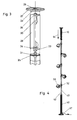
- the upper part of the lamp consists of a shell-like outer tube 10, 24 which receives the two rod-shaped low-voltage busbars 12, 13.
- the insert part 11 which is fixedly connected to the tube (for example by gluing) and which has 2 bores in the outer region for the passage of the busbars 12, 13.
- an axial bore with an internal thread is provided in the insert part 11 for receiving a guide rod 14 extending through the tube 10, 24 in the axial direction.
- the rod-shaped busbars 12, 13 are each provided with an external thread 15 at their upper ends. The ends of the busbars are each received by bores 18, 19 of a second displaceable insert 16.
- the threaded ends 15 of the busbars 12, 13 are with the help screwed by nuts 17 to the insert part 16.
- An axial bore 20 is provided in the insert part 16, which is stepped and has a larger cross section in the upper region than in the lower region.
- the axial bore 2o receives a spacer 21 which is designed as a tube for the passage of the guide rod 14.
- the guide rod 14 is screwed into an axial bore of a further insert part via an external thread, this insert part in turn being firmly connected to the upper end of the sheath of the plastic tube 24.
- the insert part has an upper threaded bore for receiving a threaded bush 25 provided with an external thread 26.
- the threaded bush 25 can be screwed in and additionally glued to the insert part and thus to the upper end of the plastic tube 24 in order to prevent loosening.
- the upper end of the plastic tube 24 forms a plate 27, by means of which the lamp according to the invention is supported on the ceiling in the assembled state.
- the plate 27 has a central bore 28 with an internal thread, so that it can be screwed onto the projecting piece of the threaded bush 25.
- the clamping of the lamp according to the invention between the floor and ceiling is explained with reference to FIG. 4.
- the lamp is designed so that the total length of the lamp exceeds the dimension between the floor and ceiling by a few centimeters.
- the compression spring 23 is thus under tension and presses the plate 27 against the ceiling, so that the lamp is securely clamped between the ceiling and floor. Since the busbars 12, 13 are only fed by a low voltage of 12 V, insulation is not necessary. As can be seen from FIG. 4, a plurality of luminaire spotlights 53 can be clamped to the busbars 42, 43 via suitable clamping parts 52 in any position.
- the clamping parts are the subject of the separate earlier application P 37 42 206.5 of the applicant.
- the two busbars 42, 43 are received in an analogous manner by a corresponding pipe part 40, preferably made of plastic, at the lower end of which there is a plate 39 which forms the bearing surface for the floor.
- a housing 36 can be provided for a transformer.
- the supply current with mains voltage reaches the transformer via line 37 and is then transformed into the 12V low voltage.
- the transformer does not have to be integrated in the lamp, but can just as well be a separate component.
- the busbars 42, 43 are not guided axially displaceably in the plastic tube 40 of the lower part of the lamp, but rather are rigid. To clamp the luminaire between the floor and the ceiling, it is sufficient if the upper part of the luminaire is resilient. However, the rest of the lamp base is similar to the resilient lamp top.
- central guide rod 44 which has an external thread 38 in its upper section and can thus be screwed to the upper insert part 41, which has a corresponding bore with an internal thread.
- the two busbars are also received in the upper section in corresponding bores of the insert part 41.
- the two busbars 42, 43 each have an external thread 45 in the lower end region.
- the lower insert 46 in turn has three holes, namely a central axial hole 50 for the passage of the guide rod 44 and two further holes 48, 49 in the outer region for the passage of the end pieces of the busbars 42, 43.
- the holes 48, 49 are in the The upper area is enlarged in cross section so that a form-fitting reception of correspondingly thickened sections of the busbars 42, 43, which are located above the thread 45, can take place. An abutment is thus provided for the end sections of the busbars 42, 43.
- the busbars 42, 43 are then fixed to the insert part 46 with the aid of the nuts 47.
- the nuts 47 have at the same time terminals 51 in the manner of luster terminals, so that the current-carrying low-voltage lines can be clamped there.
- FIG. 3 now shows how the upper part of the lamp can be easily extended if the distance between the floor and ceiling is greater than the length of the lamp, so that clamping the lamp is not easily possible.
- the upper part of the lamp is, as a comparison of Figures 3 and 1 shows, also constructed in the extended version up to the upper end of the guide rod 14 and the outer plastic tube 24. If the upper part of the lamp is to be extended upwards starting from the standard version shown in FIG. 1, the plate 27 is first unscrewed. The threaded bush 25 then protrudes somewhat beyond the end of the plastic tube 24 and the external thread 26 of the threaded bushing is exposed in the upper section.
- a type of extension rod 30 is then first screwed onto the threaded bushing 25, which has at its lower end an area with a larger external cross section and internal thread 34, that is to say an integrally formed threaded bushing 33.
- the extension rod 30 in turn has an external thread 35 at its upper end.
- a tube extension piece 29, preferably made of plastic, is required to extend the outer tube 24 to extend the lamp.
- the outer tube has a shoulder 31 at its upper end, so that a guide for the end of the tube extension piece 29 is given. After placing the pipe extension piece, the plate 27 can then be screwed on again.
- the plate has a short connection piece 32 with a slightly smaller diameter than the pipe extension piece 29, so that the short connection piece 32 can be received by the pipe extension piece 29 and thus a guide is also available for the plate 27.
- the central bore 28 with an internal thread formed in the plate enables the plate 27 to be screwed onto the external thread 35 of the extension rod 30, which extends somewhat above the pipe extension piece 29. This provides an easy way to extend the luminaire accordingly if the room height exceeds a standard dimension of 2.50 m or 2.60 m.
- the extension of the lamp can be done by the customer himself.
- the tube extension piece 29 is supplied together with the extension rod 30 by the luminaire manufacturer in various standard lengths, for example 10 cm, 20 cm etc.
Landscapes
- Engineering & Computer Science (AREA)
- General Engineering & Computer Science (AREA)
- Non-Portable Lighting Devices Or Systems Thereof (AREA)
- Fastening Of Light Sources Or Lamp Holders (AREA)
- Installation Of Indoor Wiring (AREA)
- Cage And Drive Apparatuses For Elevators (AREA)
Priority Applications (1)
| Application Number | Priority Date | Filing Date | Title |
|---|---|---|---|
| AT88121831T ATE90434T1 (de) | 1988-01-14 | 1988-12-29 | Durch einspannen zwischen boden und decke eines raumes aufstellbare leuchte. |
Applications Claiming Priority (2)
| Application Number | Priority Date | Filing Date | Title |
|---|---|---|---|
| DE3800792A DE3800792A1 (de) | 1988-01-14 | 1988-01-14 | Durch einspannen zwischen boden und decke eines raumes aufstellbare leuchte |
| DE3800792 | 1988-01-14 |
Publications (3)
| Publication Number | Publication Date |
|---|---|
| EP0324176A2 true EP0324176A2 (fr) | 1989-07-19 |
| EP0324176A3 EP0324176A3 (en) | 1990-04-04 |
| EP0324176B1 EP0324176B1 (fr) | 1993-06-09 |
Family
ID=6345209
Family Applications (1)
| Application Number | Title | Priority Date | Filing Date |
|---|---|---|---|
| EP88121831A Expired - Lifetime EP0324176B1 (fr) | 1988-01-14 | 1988-12-29 | Dispositif d'éclairage fixé par serrage entre sol et plafond |
Country Status (4)
| Country | Link |
|---|---|
| EP (1) | EP0324176B1 (fr) |
| AT (1) | ATE90434T1 (fr) |
| DE (2) | DE3800792A1 (fr) |
| ES (1) | ES2042707T3 (fr) |
Cited By (4)
| Publication number | Priority date | Publication date | Assignee | Title |
|---|---|---|---|---|
| EP0551602A1 (fr) * | 1992-01-14 | 1993-07-21 | TRILUX-LENZE GmbH & Co. KG | Monture d'éclairage |
| GB2385262A (en) * | 2002-01-10 | 2003-08-20 | Simon Wild | Self-supporting display device |
| GB2416200A (en) * | 2004-06-02 | 2006-01-18 | Bespoke Lighting Ltd | Picture Light Having Movable Light Modules |
| WO2007131644A1 (fr) * | 2006-05-17 | 2007-11-22 | Sam Schulte Gmbh + Comp. | Miroir de maquillage avec éclairage |
Families Citing this family (3)
| Publication number | Priority date | Publication date | Assignee | Title |
|---|---|---|---|---|
| DE20106936U1 (de) | 2001-04-20 | 2001-06-28 | Helestra Leuchten GmbH, 01454 Radeberg | Leuchte mit einem Träger |
| DE102015118857A1 (de) * | 2015-11-04 | 2017-05-04 | Sennheiser Electronic Gmbh & Co. Kg | Deckenlautsprechersystem |
| GB2613640B (en) | 2021-12-13 | 2024-11-20 | Redwards Consultants Ltd | Lamp assembly |
Family Cites Families (11)
| Publication number | Priority date | Publication date | Assignee | Title |
|---|---|---|---|---|
| US2977566A (en) * | 1957-06-14 | 1961-03-28 | Lightolier Inc | Lighting assembly |
| US3043611A (en) * | 1958-08-25 | 1962-07-10 | Ajax Foundry Products Inc | Electric lighting fixture assembly |
| US3072784A (en) * | 1959-12-14 | 1963-01-08 | Zelvern W Mann | Pole lamp |
| US2979605A (en) * | 1960-01-18 | 1961-04-11 | D & W Mfg Company Inc | Room divider lamp construction |
| DE1822181U (de) * | 1960-09-03 | 1960-11-24 | Ernamarie Fahr | Aufstell-lampe. |
| DE1838009U (de) * | 1961-06-16 | 1961-09-21 | Wwe Wilhelm Von Hagen Beleucht | Leuchte mit kugelgelenk und kipp- und drehbarer fassung. |
| DE2163592A1 (de) * | 1971-12-21 | 1973-08-02 | Syma System Gmbh | Beleuchtungskoerper zur anordnung an miteinander verbindbaren, einen zentralen hohlschaft aufweisenden, stabfoermigen bauelementen |
| DE8313366U1 (de) * | 1983-05-06 | 1984-02-02 | Ernst Herrmann Ing. Fabrikation Elektrischer Kontaktelemente, 1000 Berlin | Leuchte |
| DE3411929A1 (de) * | 1984-03-30 | 1985-10-10 | Patent-Treuhand-Gesellschaft für elektrische Glühlampen mbH, 8000 München | Leuchte mit wenigstens einem an einer stabfoermigen halterung verstellbar angeordneten leuchtenkopf |
| DE8534274U1 (de) * | 1985-12-05 | 1987-04-02 | Aktiebolag Fagerhults, Habo | Leuchte, vorzugsweise Stehleuchte |
| DE3711902A1 (de) * | 1986-04-08 | 1987-10-15 | Kurt Hesse | Leuchte |
-
1988
- 1988-01-14 DE DE3800792A patent/DE3800792A1/de not_active Withdrawn
- 1988-12-29 DE DE8888121831T patent/DE3881672D1/de not_active Expired - Fee Related
- 1988-12-29 EP EP88121831A patent/EP0324176B1/fr not_active Expired - Lifetime
- 1988-12-29 AT AT88121831T patent/ATE90434T1/de not_active IP Right Cessation
- 1988-12-29 ES ES88121831T patent/ES2042707T3/es not_active Expired - Lifetime
Cited By (4)
| Publication number | Priority date | Publication date | Assignee | Title |
|---|---|---|---|---|
| EP0551602A1 (fr) * | 1992-01-14 | 1993-07-21 | TRILUX-LENZE GmbH & Co. KG | Monture d'éclairage |
| GB2385262A (en) * | 2002-01-10 | 2003-08-20 | Simon Wild | Self-supporting display device |
| GB2416200A (en) * | 2004-06-02 | 2006-01-18 | Bespoke Lighting Ltd | Picture Light Having Movable Light Modules |
| WO2007131644A1 (fr) * | 2006-05-17 | 2007-11-22 | Sam Schulte Gmbh + Comp. | Miroir de maquillage avec éclairage |
Also Published As
| Publication number | Publication date |
|---|---|
| ATE90434T1 (de) | 1993-06-15 |
| EP0324176B1 (fr) | 1993-06-09 |
| ES2042707T3 (es) | 1993-12-16 |
| EP0324176A3 (en) | 1990-04-04 |
| DE3800792A1 (de) | 1989-07-27 |
| DE3881672D1 (de) | 1993-07-15 |
Similar Documents
| Publication | Publication Date | Title |
|---|---|---|
| DE2320983A1 (de) | Einspeise- bzw. abnehmevorrichtung fuer stromschienen | |
| DE2550245A1 (de) | Anschlussklemme fuer eine vorrichtung oder ein element zur elektrischen verbindung | |
| DE102014004343A1 (de) | Zuruckziehbare Endkappe für LED-Röhre | |
| DE29806645U1 (de) | Kabelsteckverbinder | |
| AT407906B (de) | Elektrisches leuchtensystem | |
| EP0324176B1 (fr) | Dispositif d'éclairage fixé par serrage entre sol et plafond | |
| EP0291989A1 (fr) | Barre omnibus à basse tension | |
| DE2538604A1 (de) | Elektrisches schaltgeraet | |
| DE3817133C2 (fr) | ||
| DE19750100C2 (de) | Verbindungsvorrichtung | |
| DE8408553U1 (de) | Lampensockel für eine elektrische Lampe mit zwei Glühbirnen | |
| DE4220641C1 (de) | Leuchte für eine Niedervolt-Reflektorlampe | |
| DE3784089T2 (de) | Beleuchtungssystem mit mehreren beleuchtungseinheiten. | |
| DE3908532C2 (fr) | ||
| DE7618061U1 (de) | Verbindungsstueck zum loesbaren verbinden von wenigstens zwei elementen eines beleuchtungskoerpers | |
| DE8915575U1 (de) | Kabelklemme | |
| DE2060475C3 (de) | Kabelanschluß eines explosionsgeschfitzten Gerätes | |
| DE69710504T2 (de) | Lampenfassung | |
| DE2900958A1 (de) | Warnleuchte | |
| CH661111A5 (en) | Device for the simple fitting of electric lamps | |
| EP0649196A1 (fr) | Système d'installation à basse tension | |
| DE102006017916B3 (de) | Elektrisches Installationsgerät | |
| DE10160543A1 (de) | Stromwandler für eine NH-Sicherungsleiste, NH-Sicherungs-Lastschalteinrichtung oder dergleichen | |
| DE3223819A1 (de) | Sicherungskasten | |
| DE3112503A1 (de) | "mastleuchtenanordnung" |
Legal Events
| Date | Code | Title | Description |
|---|---|---|---|
| PUAI | Public reference made under article 153(3) epc to a published international application that has entered the european phase |
Free format text: ORIGINAL CODE: 0009012 |
|
| AK | Designated contracting states |
Kind code of ref document: A2 Designated state(s): AT BE CH DE ES FR GB GR IT LI LU NL SE |
|
| PUAL | Search report despatched |
Free format text: ORIGINAL CODE: 0009013 |
|
| AK | Designated contracting states |
Kind code of ref document: A3 Designated state(s): AT BE CH DE ES FR GB GR IT LI LU NL SE |
|
| 17P | Request for examination filed |
Effective date: 19900519 |
|
| 17Q | First examination report despatched |
Effective date: 19920820 |
|
| GRAA | (expected) grant |
Free format text: ORIGINAL CODE: 0009210 |
|
| AK | Designated contracting states |
Kind code of ref document: B1 Designated state(s): AT BE CH DE ES FR GB GR IT LI LU NL SE |
|
| REF | Corresponds to: |
Ref document number: 90434 Country of ref document: AT Date of ref document: 19930615 Kind code of ref document: T |
|
| REF | Corresponds to: |
Ref document number: 3881672 Country of ref document: DE Date of ref document: 19930715 |
|
| ITF | It: translation for a ep patent filed | ||
| ET | Fr: translation filed | ||
| GBT | Gb: translation of ep patent filed (gb section 77(6)(a)/1977) |
Effective date: 19931020 |
|
| REG | Reference to a national code |
Ref country code: GR Ref legal event code: FG4A Free format text: 3009006 |
|
| REG | Reference to a national code |
Ref country code: ES Ref legal event code: FG2A Ref document number: 2042707 Country of ref document: ES Kind code of ref document: T3 |
|
| PLBE | No opposition filed within time limit |
Free format text: ORIGINAL CODE: 0009261 |
|
| STAA | Information on the status of an ep patent application or granted ep patent |
Free format text: STATUS: NO OPPOSITION FILED WITHIN TIME LIMIT |
|
| 26N | No opposition filed | ||
| PGFP | Annual fee paid to national office [announced via postgrant information from national office to epo] |
Ref country code: GB Payment date: 19941216 Year of fee payment: 7 |
|
| PGFP | Annual fee paid to national office [announced via postgrant information from national office to epo] |
Ref country code: SE Payment date: 19941219 Year of fee payment: 7 |
|
| EAL | Se: european patent in force in sweden |
Ref document number: 88121831.7 |
|
| PGFP | Annual fee paid to national office [announced via postgrant information from national office to epo] |
Ref country code: FR Payment date: 19951110 Year of fee payment: 8 |
|
| PGFP | Annual fee paid to national office [announced via postgrant information from national office to epo] |
Ref country code: NL Payment date: 19951114 Year of fee payment: 8 |
|
| PGFP | Annual fee paid to national office [announced via postgrant information from national office to epo] |
Ref country code: AT Payment date: 19951117 Year of fee payment: 8 |
|
| PGFP | Annual fee paid to national office [announced via postgrant information from national office to epo] |
Ref country code: BE Payment date: 19951120 Year of fee payment: 8 |
|
| PGFP | Annual fee paid to national office [announced via postgrant information from national office to epo] |
Ref country code: GR Payment date: 19951128 Year of fee payment: 8 |
|
| PGFP | Annual fee paid to national office [announced via postgrant information from national office to epo] |
Ref country code: LU Payment date: 19951201 Year of fee payment: 8 Ref country code: CH Payment date: 19951201 Year of fee payment: 8 |
|
| PGFP | Annual fee paid to national office [announced via postgrant information from national office to epo] |
Ref country code: ES Payment date: 19951211 Year of fee payment: 8 |
|
| PGFP | Annual fee paid to national office [announced via postgrant information from national office to epo] |
Ref country code: DE Payment date: 19951215 Year of fee payment: 8 |
|
| PG25 | Lapsed in a contracting state [announced via postgrant information from national office to epo] |
Ref country code: GB Effective date: 19951229 |
|
| PG25 | Lapsed in a contracting state [announced via postgrant information from national office to epo] |
Ref country code: SE Effective date: 19951230 |
|
| GBPC | Gb: european patent ceased through non-payment of renewal fee |
Effective date: 19951229 |
|
| PG25 | Lapsed in a contracting state [announced via postgrant information from national office to epo] |
Ref country code: LU Free format text: LAPSE BECAUSE OF NON-PAYMENT OF DUE FEES Effective date: 19961229 Ref country code: AT Effective date: 19961229 |
|
| PG25 | Lapsed in a contracting state [announced via postgrant information from national office to epo] |
Ref country code: ES Free format text: LAPSE BECAUSE OF EXPIRATION OF PROTECTION Effective date: 19961230 |
|
| PG25 | Lapsed in a contracting state [announced via postgrant information from national office to epo] |
Ref country code: LI Effective date: 19961231 Ref country code: CH Effective date: 19961231 Ref country code: BE Effective date: 19961231 |
|
| BERE | Be: lapsed |
Owner name: JOSEF SOLKEN G.M.B.H. & CO. K.G. Effective date: 19961231 |
|
| PG25 | Lapsed in a contracting state [announced via postgrant information from national office to epo] |
Ref country code: GR Free format text: THE PATENT HAS BEEN ANNULLED BY A DECISION OF A NATIONAL AUTHORITY Effective date: 19970630 |
|
| PG25 | Lapsed in a contracting state [announced via postgrant information from national office to epo] |
Ref country code: NL Effective date: 19970701 |
|
| REG | Reference to a national code |
Ref country code: GR Ref legal event code: MM2A Free format text: 3009006 |
|
| REG | Reference to a national code |
Ref country code: CH Ref legal event code: PL |
|
| PG25 | Lapsed in a contracting state [announced via postgrant information from national office to epo] |
Ref country code: FR Effective date: 19970829 |
|
| NLV4 | Nl: lapsed or anulled due to non-payment of the annual fee |
Effective date: 19970701 |
|
| PG25 | Lapsed in a contracting state [announced via postgrant information from national office to epo] |
Ref country code: DE Effective date: 19970902 |
|
| REG | Reference to a national code |
Ref country code: FR Ref legal event code: ST |
|
| REG | Reference to a national code |
Ref country code: ES Ref legal event code: FD2A Effective date: 20010301 |
|
| PG25 | Lapsed in a contracting state [announced via postgrant information from national office to epo] |
Ref country code: IT Free format text: LAPSE BECAUSE OF NON-PAYMENT OF DUE FEES;WARNING: LAPSES OF ITALIAN PATENTS WITH EFFECTIVE DATE BEFORE 2007 MAY HAVE OCCURRED AT ANY TIME BEFORE 2007. THE CORRECT EFFECTIVE DATE MAY BE DIFFERENT FROM THE ONE RECORDED. Effective date: 20051229 |