EP0551602A1 - Monture d'éclairage - Google Patents
Monture d'éclairage Download PDFInfo
- Publication number
- EP0551602A1 EP0551602A1 EP92120378A EP92120378A EP0551602A1 EP 0551602 A1 EP0551602 A1 EP 0551602A1 EP 92120378 A EP92120378 A EP 92120378A EP 92120378 A EP92120378 A EP 92120378A EP 0551602 A1 EP0551602 A1 EP 0551602A1
- Authority
- EP
- European Patent Office
- Prior art keywords
- arm
- luminaire
- angle piece
- lamp
- foot
- Prior art date
- Legal status (The legal status is an assumption and is not a legal conclusion. Google has not performed a legal analysis and makes no representation as to the accuracy of the status listed.)
- Withdrawn
Links
- 230000000452 restraining effect Effects 0.000 claims description 6
- 238000004873 anchoring Methods 0.000 description 2
- 229910052751 metal Inorganic materials 0.000 description 2
- 239000002184 metal Substances 0.000 description 2
- 230000001154 acute effect Effects 0.000 description 1
- 229910052782 aluminium Inorganic materials 0.000 description 1
- XAGFODPZIPBFFR-UHFFFAOYSA-N aluminium Chemical compound [Al] XAGFODPZIPBFFR-UHFFFAOYSA-N 0.000 description 1
- 230000006835 compression Effects 0.000 description 1
- 238000007906 compression Methods 0.000 description 1
- 230000000694 effects Effects 0.000 description 1
- 238000001125 extrusion Methods 0.000 description 1
- 238000000034 method Methods 0.000 description 1
- 238000005192 partition Methods 0.000 description 1
- 230000002093 peripheral effect Effects 0.000 description 1
Images

Classifications
-
- F—MECHANICAL ENGINEERING; LIGHTING; HEATING; WEAPONS; BLASTING
- F21—LIGHTING
- F21V—FUNCTIONAL FEATURES OR DETAILS OF LIGHTING DEVICES OR SYSTEMS THEREOF; STRUCTURAL COMBINATIONS OF LIGHTING DEVICES WITH OTHER ARTICLES, NOT OTHERWISE PROVIDED FOR
- F21V21/00—Supporting, suspending, or attaching arrangements for lighting devices; Hand grips
- F21V21/10—Pendants, arms, or standards; Fixing lighting devices to pendants, arms, or standards
- F21V21/12—Pendants, arms, or standards; Fixing lighting devices to pendants, arms, or standards capable of being elongated or shortened by the insertion or removal of intermediate pieces
Definitions
- the invention relates to a luminaire frame for table lamps, floor lamps and other lamps which have a lamp arm which is provided at one end with a foot and at the other end with a lamp housing.
- a luminaire frame with the features of the preamble of claim 1 is known from US-A-2 665 870.
- This luminaire frame has a lamp arm made of two pivotable arm sections, one arm section containing a pulling element which is anchored in the joint connecting the arm sections and on opposite end in the foot is tensioned by a spring.
- This traction member serves to balance the lamp arm, which is pivotable with respect to the foot, so that the position of the lamp arm is stable in any pivot position.
- the ends of the lamp arm are screwed into the corresponding joint parts. If the lamp arm on the foot could not be swiveled, the compensation device with the traction element would not be required.
- a similar luminaire frame is known from FR-A-1 172 498.
- the luminaire arm is also fastened to the base with a joint and the various arm sections of the luminaire arm are connected to one another by joints.
- the arm sections do not contain any traction elements, but rather rods and tubes, which serve as electrical lines for connecting the two power poles to the lamp housing.
- the rods are length-compensated by compression springs.
- the lamp arm is connected to the foot and the lamp housing by screwing.
- the invention has for its object to provide a luminaire frame that is easy to assemble from prefabricated parts, has great rigidity and strength and in which the individual components are not directly screwed together.
- the arm sections which run at an angle to one another consist of hollow profiles which have a constant cross section over their length, but do not have to be round. Such hollow profiles can be produced, for example, in the extrusion process.
- the hollow profiles are connected by an elbow, which is manufactured separately.
- Tension elements extend over the entire length within the hollow profiles.
- Each of the arm sections is initially loosely attached to the adjacent part, namely the foot, the angle piece or the lamp housing, without any restraining intervention.
- the restraining force with which the arm sections are held on the adjacent components is exerted exclusively by the tension member acting as an anchoring element.
- the entire luminaire frame is held together by the traction element without threads or holes for fastening parts having to be attached to the arm sections.
- the invention enables a safe and rigid attachment of additional parts to the ends of the arm sections, the additional parts having no play or movement.
- the luminaire frame thus becomes rigid in itself, without fastening elements visible from the outside.
- the luminaire frame according to the invention can thus be varied within the framework of a modular system, arm sections and traction elements of different lengths being present.
- the lamp frame can be used either for a table lamp or a floor lamp.
- the angle can be changed by using different elbows.
- the luminaire frame thus offers numerous options for variation, each only individual components need to be replaced. In principle, the same hollow profiles can be used for all types of luminaire frames.
- the luminaire frame is particularly suitable for a luminaire arm which has two angled sections, the angle piece forming the anchoring part for the traction elements of the two adjacent arm sections.
- the two arm sections are braced at the ends facing away from the end piece, that is to say without interference with the structure which is visible from the outside.
- Wing nuts are preferably used as tensioning elements, which allow the tension members to be tensioned by hand without tools.
- the luminaire frame can then be assembled from the individual components without the use of tools.
- the luminaire frame according to the invention is particularly suitable for workplace luminaires and work zone luminaires in which the light is preferably directed onto a work surface or a zone and the luminaire frame does not impair the area to be illuminated.
- the luminaire housing can be mounted in different positions on the luminaire frame, the luminaire housing being aligned (in plan view) in the extension of the luminaire frame and also transversely.
- the luminaire frame enables these two arrangements using the same components, which only have to be mounted in different orientations.
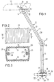
- a lamp arm 10 which consists of a straight lower arm section 11, a straight upper arm section 12, an angle piece 13 connecting the arm sections 11 and 12, a further angle piece 14 at the end of the upper lamp arm 12, one the further angle piece 14 supported support plate 15 and an adapter plate 16.
- the luminaire housing 17, in which a light source is located, is fastened to the support plate 15.
- a foot 18 is provided, on which the entire lamp frame 10 rests. This foot 18 is designed here as a holding device for attachment to a table top 19, but it can also consist, for example, of a table that can be set up on the floor if the lower arm section 11 has a greater length.
- the two arm sections 11 and 12 consist of mutually identical hollow profiles 20 made of metal, preferably aluminum.
- the hollow profile 20 has a tubular rectangular structure with a closed peripheral wall, longitudinal grooves 23 being provided on the outer sides of the opposite main walls 21 and 22, while the narrower side walls 24 and 25 are smooth and convexly curved outwards.
- Profile webs 26 protrude inward from the side walls 24 and 25 and form C-shaped guide channels 27 for receiving a respective pulling element 28.
- the guide channels 27 enclose each traction element 28 by more than 180 °, so that the traction elements are not moved laterally out of the guide channels but can only be inserted into the guide channels in the longitudinal direction.
- the traction elements 28 are rigid rods made of metal, which each extend over the entire length of an arm section 11, 12 and are provided with threads 29 and 30 at their ends.
- an end piece 31 is attached to the lower end of the lower arm section 11, through which the traction elements 28 pass.
- Nuts 32 are screwed onto the threads 29 of the tension members 28, which are supported on the underside of the end piece 31 and with which the tension members 28 can be tightened.
- Plates 33 and 34 which form the foot 18 and between which a table top 19 with wing nuts 35 can be clamped, are pushed onto the protruding end sections of the traction members 28.
- the end piece 31 and the plates 33 and 34 have central openings 36 in order to be able to lead cables through the interior of the lamp frame.
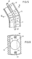
- the outer contour of the angle piece 13 is adapted to the outer contours of the two arm sections 11 and 12, so it has an essentially rectangular cross section. It has a transverse partition 40 with a central opening 41 for the passage of cables. From the intermediate wall 41 project in the longitudinal direction of the respective adjacent arm section 11 or 12 bushings 42 and 43 with an internal thread for screwing in the thread 30 of the tension members 18.
- the bushes 43 are arranged in alignment with the guide channels 27 of the arm sections 11 and 12. This ensures that the angle piece 13 cannot rotate relative to the arm sections 11 and 12.
- the two tension members 18 running eccentrically in the arm sections thus ensure a torsion-free fastening of the angle piece 13 to the arm sections. If the traction elements 18 have been tightened with the nuts 32, the arm section 11 is firmly clamped between the end piece 31 and the angle piece 13, the end piece and angle piece not being able to move relative to the arm section 11.
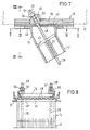
- the further angle piece 14 is placed, which is also hollow and whose angle has the same size as that of the angle piece 13, so that the angle piece 14 compensates the effect of the angle piece 13 to a certain extent.
- the angle piece 14 accordingly has a horizontal top wall 45 and at its lower end an opening 46 for the passage of cables. In the upper wall 45 there is a recess 47 which is larger than the opening 46.
- Guide channels for the traction elements 28 are not present in the angle piece 14. Through the inside of this elbow 14, the tension members 28 go straight through so that they cross the plane of the top wall 45 at an acute angle.
- the top wall 45 of the further angle piece 14 is square and crenellations 48 are arranged at regular intervals along its circumference.
- the support plate 15 is placed against the upper wall 45 of the angle piece 14.
- This support plate consists of a profile which has longitudinal grooves 49 on its underside.
- the protruding crenellations 48 of the angle piece 14 penetrate into the grooves 49, so that the support plate 15 is held on the angle piece 14 in a manner preventing rotation. It is possible to arrange the support plate 15 rotated by 90 ° on the upper wall 45 of the angle piece 14 because the crenellations 48, which are arranged both on the long sides and on the transverse sides of the upper side 45, make this possible.
- the support plate 15 has a pair of elongated holes 50 for the passage of the oblique tension members 18, which are arranged on both sides of an opening 58 for cables. Another pair of elongated holes 51 is arranged at right angles to the elongated holes 50. Through this pair of elongated holes 51, the tension members 28 pass when the support plate 15 has been rotated by 90 °. Finally, the support plate 15 has a pair of holes 52 in order to be able to attach the lamp housing 17 to it. This is done with screws which are placed against the support plate 15 from below and which are later taken up by the angle piece 14.
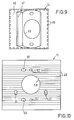
- the adapter plate 16 is placed on the support plate 15.
- the adapter plate has oblique bores 55 for the passage of the traction elements 28 which pass obliquely through the elongated holes 50.
- the oblique bore 55 opens into a support surface 56 which extends at right angles to the oblique bore is pressed against the support surface 56 and thereby braces the tension member 28, the other end of which is anchored in the angle piece 13.
- the adapter plate 16 is always mounted in the same orientation to the angle piece 14, even if the support plate 15 is rotated by 90 °.
- the adapter plate 16 has an opening (not shown) that is aligned with the opening 58 of the support plate 15 for the passage of cables.
Landscapes
- Engineering & Computer Science (AREA)
- General Engineering & Computer Science (AREA)
- Non-Portable Lighting Devices Or Systems Thereof (AREA)
Applications Claiming Priority (2)
| Application Number | Priority Date | Filing Date | Title |
|---|---|---|---|
| DE19924200668 DE4200668A1 (de) | 1992-01-14 | 1992-01-14 | Leuchtengestell |
| DE4200668 | 1992-01-14 |
Publications (1)
| Publication Number | Publication Date |
|---|---|
| EP0551602A1 true EP0551602A1 (fr) | 1993-07-21 |
Family
ID=6449443
Family Applications (1)
| Application Number | Title | Priority Date | Filing Date |
|---|---|---|---|
| EP92120378A Withdrawn EP0551602A1 (fr) | 1992-01-14 | 1992-11-28 | Monture d'éclairage |
Country Status (2)
| Country | Link |
|---|---|
| EP (1) | EP0551602A1 (fr) |
| DE (1) | DE4200668A1 (fr) |
Families Citing this family (1)
| Publication number | Priority date | Publication date | Assignee | Title |
|---|---|---|---|---|
| RU2121107C1 (ru) * | 1997-10-02 | 1998-10-27 | Общество с ограниченной ответственностью "МНПП СВЭН" | Устройство для наружного освещения |
Citations (3)
| Publication number | Priority date | Publication date | Assignee | Title |
|---|---|---|---|---|
| AT294974B (de) * | 1968-10-24 | 1971-12-10 | J T Kalmar Kommanditgesellscha | Rohrverbindung für mehrachsige, räumliche Rohrverzweigungen an Raumausstattungselementen, Einrichtungsgegenständen, mehrflammigen Leuchten od.dgl. |
| EP0324176A2 (fr) * | 1988-01-14 | 1989-07-19 | JOSEF SÖLKEN GMBH & CO. KG | Dispositif d'éclairage fixé par serrage entre sol et plafond |
| DE3905089A1 (de) * | 1988-02-18 | 1989-08-31 | Guss Peter | Leuchtensystem |
Family Cites Families (4)
| Publication number | Priority date | Publication date | Assignee | Title |
|---|---|---|---|---|
| US2665870A (en) * | 1950-05-27 | 1954-01-12 | Milton Fletcher | Adjustable bracket structure |
| FR1172498A (fr) * | 1957-04-25 | 1959-02-11 | Lampe d'éclairage orientable | |
| DE3230099A1 (de) * | 1981-09-02 | 1983-03-10 | Günter 4920 Lemgo Kotzolt | Winkelstueck zur verbindung von lichtrohren |
| DE3604319A1 (de) * | 1986-02-12 | 1987-08-13 | Hoffmeister Leuchten Kg | Vorrichtung zur verbindung von einen laengsschlitz aufweisenden verkleidungsrohren fuer lichtschienen |
-
1992
- 1992-01-14 DE DE19924200668 patent/DE4200668A1/de not_active Withdrawn
- 1992-11-28 EP EP92120378A patent/EP0551602A1/fr not_active Withdrawn
Patent Citations (3)
| Publication number | Priority date | Publication date | Assignee | Title |
|---|---|---|---|---|
| AT294974B (de) * | 1968-10-24 | 1971-12-10 | J T Kalmar Kommanditgesellscha | Rohrverbindung für mehrachsige, räumliche Rohrverzweigungen an Raumausstattungselementen, Einrichtungsgegenständen, mehrflammigen Leuchten od.dgl. |
| EP0324176A2 (fr) * | 1988-01-14 | 1989-07-19 | JOSEF SÖLKEN GMBH & CO. KG | Dispositif d'éclairage fixé par serrage entre sol et plafond |
| DE3905089A1 (de) * | 1988-02-18 | 1989-08-31 | Guss Peter | Leuchtensystem |
Also Published As
| Publication number | Publication date |
|---|---|
| DE4200668A1 (de) | 1993-07-15 |
Similar Documents
| Publication | Publication Date | Title |
|---|---|---|
| DE69118289T2 (de) | Trennwand | |
| EP0790792A1 (fr) | Table | |
| EP1312852B1 (fr) | Dispositif pour la formation d'une paroi support pour écrans plats | |
| EP0818164B1 (fr) | Structure porteuse pour meuble de travail | |
| DE3509554C2 (fr) | ||
| EP0572936A1 (fr) | Rail | |
| DE10019292B4 (de) | Modulares Tischsystem | |
| DE4124066C2 (de) | Elektrisches Leuchtensystem | |
| DE19537016C1 (de) | Rahmengestell für einen Schaltschrank | |
| EP1984582B1 (fr) | Plafond intérieur suspendu et éléments composant celui-ci | |
| EP0743415B1 (fr) | Plaques de montage jumelées pour la fixation de bras de charnière de charnières de meubles ou autres | |
| DE19831453A1 (de) | Einstellbare Befestigung für Gegenstände, insbesondere Glasplatten auf einer Unterkonstruktion | |
| AT403839B (de) | Halter insbesondere für rohre, kabelstränge und hohlleiter | |
| DE2809674C2 (de) | Unterdecke | |
| EP0943824A1 (fr) | Dispositif de fixation | |
| DE19734629A1 (de) | Vorrichtung zur Aufhängung von Rohren unter Decken | |
| EP0551602A1 (fr) | Monture d'éclairage | |
| DE3031095A1 (de) | Gliedertreppe | |
| DE19859473B4 (de) | Geräteständer | |
| EP0547438A1 (fr) | Charnière à axe unique | |
| CH719422B1 (de) | Verbindungseinrichtung für Tragelemente für ein Traggerüst sowie ein Traggerüst für Personen- und/oder Warenaufzüge | |
| EP0639134B1 (fr) | Dispositif de verrouillage | |
| DE2315982A1 (de) | Befestigungsvorrichtung fuer motoren, getriebegehaeuse, variatoren oder dgl., insbesondere fuer einen elektromotor, der bei einem maschinenwerkzeug oder dgl. eine riemenscheibe treibt | |
| EP1180636A1 (fr) | Dispositif réglable d'accouplement | |
| DE2626989A1 (de) | Loesbare, insbesondere fuer moebel verwendbare verbindung |
Legal Events
| Date | Code | Title | Description |
|---|---|---|---|
| PUAI | Public reference made under article 153(3) epc to a published international application that has entered the european phase |
Free format text: ORIGINAL CODE: 0009012 |
|
| AK | Designated contracting states |
Kind code of ref document: A1 Designated state(s): AT BE CH DE ES FR GB IT LI LU NL |
|
| 17P | Request for examination filed |
Effective date: 19930915 |
|
| 17Q | First examination report despatched |
Effective date: 19940712 |
|
| STAA | Information on the status of an ep patent application or granted ep patent |
Free format text: STATUS: THE APPLICATION HAS BEEN WITHDRAWN |
|
| 18W | Application withdrawn |
Withdrawal date: 19941125 |