EP0324219A2 - Moteur à condensateur à résonance série - Google Patents
Moteur à condensateur à résonance série Download PDFInfo
- Publication number
- EP0324219A2 EP0324219A2 EP88307192A EP88307192A EP0324219A2 EP 0324219 A2 EP0324219 A2 EP 0324219A2 EP 88307192 A EP88307192 A EP 88307192A EP 88307192 A EP88307192 A EP 88307192A EP 0324219 A2 EP0324219 A2 EP 0324219A2
- Authority
- EP
- European Patent Office
- Prior art keywords
- winding
- motor
- capacitor
- switch
- series
- Prior art date
- Legal status (The legal status is an assumption and is not a legal conclusion. Google has not performed a legal analysis and makes no representation as to the accuracy of the status listed.)
- Granted
Links
Images


Classifications
-
- H—ELECTRICITY
- H02—GENERATION; CONVERSION OR DISTRIBUTION OF ELECTRIC POWER
- H02K—DYNAMO-ELECTRIC MACHINES
- H02K17/00—Asynchronous induction motors; Asynchronous induction generators
- H02K17/02—Asynchronous induction motors
- H02K17/04—Asynchronous induction motors for single phase current
- H02K17/08—Motors with auxiliary phase obtained by externally fed auxiliary windings, e.g. capacitor motors
-
- H—ELECTRICITY
- H02—GENERATION; CONVERSION OR DISTRIBUTION OF ELECTRIC POWER
- H02K—DYNAMO-ELECTRIC MACHINES
- H02K99/00—Subject matter not provided for in other groups of this subclass
- H02K99/20—Motors
Definitions
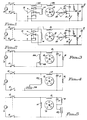
- the motor of Figure 1 causes a substantial portion of the total current at start up to flow through the winding 14. This current, however, rapidly drops to near zero, with essentially all of the operating current flowing through the run winding sections 13A and 13B. This shift of the current flow occurs automatically as a result of the characteristics of the series resonant circuit, so that the start winding 14 may be made of relatively small diameter wire. There is no danger of burnout of the starting winding since it never carries any high current for any prolonged period of time. In fact, during normal run operation of the motor, the start winding 14 could be switched entirely out of the circuit, if desired. This is not necessary, however, since the current automatically drops to zero or near zero due to the inherent operating characteristics of the motor.
- the reversing switch 19 When the reversing switch 19 has the poles moved to the right, the left-hand end of the winding 13 is connected to the switch 10, and the lower terminal of the capacitor 17 is connected in common with the lower end of the winding 14 to the bottom or return side of the power supply 9 by way of the switch 12.
- the poles of the reversing switch 19 When the poles of the reversing switch 19 are moved to the left, as viewed in Figure 2, the left hand end of the winding 13 is connected through the poles of the switch 19 to the lower end of the winding 14 and the switch 12.
- the lower terminal of the capacitor 17 then is connected through the switch 19 (the upper pole thereof) to the switch 10, thereby reversing the connections of the series resonant circuit 13, 17 with respect to the winding 14.
- Figures 3, 4 and 5 illustrate motors with moderate starting torque, which have a further provision for varying the speed of operation of the rotation of the rotor 15.
- the winding arrangements of the circuits of Figures 3, 4 and 5 for the run winding 13 and start winding 14 essentially are the same as the arrangement shown in Figure 2.
- the capacitor 17 is in series with the run winding 13 (having large diameter wire) to form a series resonant circuit at the operating frequency of the alternating current power supply from the source 9.
- the start winding comprises a two section winding, 14A and 14B.
- the winding 14A is comparable to the winding 14 of Figures 1 and 2.
- the circuit of Figure 5 employs a reactor (auto transformer) in series with the series-connected run winding 13 and capacitor 17. Instead of returning the lower terminal of the capacitor 17 directly to the switch 12, the reactor 20 is connected between switch 12 and the capacitor 17.
- the variation of the reactance of the reactor 20, as established by the setting of the slide point, functions to change the voltage across the capacitor 17, which in turn operates to change the power of the motor.
- the starting winding 14 briefly carries practically all of the current at initial startup. Because the two windings are electrically dephased by 90° on the stator, high starting torque is developed, but the current flow through the winding 14 rapidly drops off as the rotation of the rotor 15 increases.
- the final running current through the winding 13 is controlled by the size of the capacitor 17.
- the series resonance of the circuit consisting of the winding 13 and the capacitor 17 builds a maximum current through the run winding 13 to an amount which is limited by the capacitance of the capacitor and the voltage applied across the capacitor 17. This series resonance takes place immediately upon motor starting and throughout full load and no load running conditions of operations.
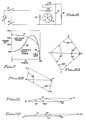
- Figures 9A through 9D are vector diagrams of the operating characteristics of the motor of Figure 1 which have the voltage vector diagrams superimposed over the current diagrams of Figures 8A through 8D.
- the current vectors are the same as those shown in Figures 8A through 8D, and the voltage vectors constitute the vectors AV/BV (for winding 13A) and BV/CV (for the run winding section 13B).
- the vector 0/BV constitutes the voltage across the start winding 14, and the vector 0/CV constitutes the line voltage.
- Figure 9D shows the operating current and voltage vectors for the motor of Figure 1 under no load conditions of operation.
- the operating speed essentially is the full operating RPM of the motor as illustrated by the point 33 on the curves of Figure 7.
- the motor as originally designed, draws 7.4 amperes for a one horsepower output; so that the modified winding configuration employing the series resonant circuit of the combination of the windings 13A, 13B and capacitor 17 results in significantly higher efficiency during the full load or running condition of operation of the motor.
- Figures 10 through 13 illustrate the current and voltage vectors for a motor constructed in accordance with the circuit configuration of Figure 2.
- Figure 10 is the full load vector diagram
- Figure 11 is the start condition vector diagram with the switch 21 closed
- Figure 12 is the start condition vector diagram with the switch 21 open
- Figure 13 is the no load vector diagram.
- the different phase angles are shown and the current vector designations and voltage vector designations which are employed in Figures 10, 11, 12 and 13 are comparable to the ones which have been used in Figures 9A through 9D.
- the current vectors simply use letter designations (ABC) with an origin "0", whereas the voltage vectors use the designations AV,BV in conjunction with the origin "0".
- the current vector 0A of Figure 11 represents the current through the start winding 14, and the vector AB represents the current through the run winding 13 of Figure 2.
- the voltage vector 0/AV is the capacitor voltage of the capacitor 17 and the vector AV/BV constitutes the voltage across the run winding 13.
- the line voltage is the vector 0/BV.
- the line current is the vector 0B, as illustrated in Figure 11.
- the vectors of Figure 11 comprise the start conditions of the high torque version of the motor which occurs with the switch 21 closed.
- Figure 12 illustrates the same vectors for the motor when the switch 21 is open. This motor develops a moderate starting torque, compared with the conditions of operation illustrated in Figure 11; and the vectors of Figure 12 include the same designations primed (′) as are used in Figure 11.
- the motor was a standard Dayton motor, frame 56, model 5K4310. As mentioned above, this was a one horsepower motor, 1,725 RPM, 230 volts, 7.4 amperes.
- the stator was rewound in accordance with the configuration of Figure 2 with number 16 wire for the winding 13 and with number 18 wire for the winding 14. The number of turns of each winding was essentially the same as in the original motor.
- the capacitor 17 was 50 MFD at 320VAC.
- the motor of Figure 2 develops a high starting torque, approximately 14 foot pounds at 34 amperes.
- This starting torque is comparable to the starting torque of the conventional motor, but with the advantage that the starting winding 14 will not burn out, since the current through it is a maximum of approximately 20 amperes; and this current does not persist for any significant period of time.
- the moderate starting torque is approximately 3.1 foot pounds at 19 amperes.
- the breakdown torque of the motor at full load is approximately 9 foot pounds at 1,650 RPM.
- the motor at full load operates with a current of 5.0 amperes and 240 volts.
- the rated full load current is 7.4 amperes for the same motor frame with a standard winding configuration.
- the motor of Figure 2 however, has significantly higher starting torque.
Landscapes
- Engineering & Computer Science (AREA)
- Power Engineering (AREA)
- Motor And Converter Starters (AREA)
- Control Of Ac Motors In General (AREA)
Applications Claiming Priority (2)
| Application Number | Priority Date | Filing Date | Title |
|---|---|---|---|
| US07/144,544 US4794288A (en) | 1988-01-15 | 1988-01-15 | Series resonant capacitor motor |
| US144544 | 1988-01-15 |
Publications (3)
| Publication Number | Publication Date |
|---|---|
| EP0324219A2 true EP0324219A2 (fr) | 1989-07-19 |
| EP0324219A3 EP0324219A3 (en) | 1989-11-29 |
| EP0324219B1 EP0324219B1 (fr) | 1993-03-24 |
Family
ID=22509063
Family Applications (1)
| Application Number | Title | Priority Date | Filing Date |
|---|---|---|---|
| EP19880307192 Expired - Lifetime EP0324219B1 (fr) | 1988-01-15 | 1988-08-03 | Moteur à condensateur à résonance série |
Country Status (8)
| Country | Link |
|---|---|
| US (1) | US4794288A (fr) |
| EP (1) | EP0324219B1 (fr) |
| JP (1) | JPH01218372A (fr) |
| AU (1) | AU599258B2 (fr) |
| BR (1) | BR8805739A (fr) |
| CA (1) | CA1281358C (fr) |
| DE (1) | DE3879663T2 (fr) |
| MX (1) | MX165210B (fr) |
Families Citing this family (18)
| Publication number | Priority date | Publication date | Assignee | Title |
|---|---|---|---|---|
| US4959573A (en) * | 1986-08-27 | 1990-09-25 | S.P.C. Holding, Co., Ltd. | Electromagnetic induction machines having regulated polar magnetic symmetry |
| US4794288A (en) * | 1988-01-15 | 1988-12-27 | Lewus Alexander J | Series resonant capacitor motor |
| US5166568A (en) * | 1989-06-20 | 1992-11-24 | Whirlpool Corporation | PSC motor for automatic washer |
| ATE159060T1 (de) * | 1989-06-20 | 1997-10-15 | Whirlpool Co | Motor mit einem ständig angeschlossenen phasenverschiebungskondensator für eine waschmaschine |
| US5227710A (en) * | 1989-12-28 | 1993-07-13 | The Alexander J. Lewus Revocable Inter Vivos (Living) Trust | Multiple speed single phase motor |
| US5029265A (en) * | 1990-01-11 | 1991-07-02 | Staats Gustav W | Motor controller having a control loop for neutralizing rotor leakage and magnetizing reactances |
| DE4124285C2 (de) * | 1991-07-22 | 2001-04-26 | Snap On Deutschland Holding | Vorrichtung zum Messen der Unwucht eines Rotors |
| US5212436A (en) * | 1991-12-06 | 1993-05-18 | Texas Instruments Incorporated | Single phase motor start system |
| JP3132992B2 (ja) * | 1995-10-31 | 2001-02-05 | 三菱電機株式会社 | ロータ組立装置 |
| US6633154B1 (en) * | 2000-01-04 | 2003-10-14 | William B. Duff, Jr. | Method and circuit for using polarized device in AC applications |
| US6566839B2 (en) * | 2001-06-28 | 2003-05-20 | Pelco | Switched capacitor motor driver |
| US6721496B2 (en) | 2001-10-24 | 2004-04-13 | Marcus Allen Smith | Electrical resonance circuits for high efficiency direct current motors |
| US20080159876A1 (en) * | 2007-01-03 | 2008-07-03 | Keener Robert M | Protective device for a controlling system of a sewage pump |
| CN102780344A (zh) * | 2012-08-17 | 2012-11-14 | 张湘明 | 单相电容运转异步电动机 |
| US9997983B2 (en) * | 2015-01-08 | 2018-06-12 | Performa, LLC | Multiple winding design for single or polyphase electric motors with a cage type rotor |
| US10560033B2 (en) * | 2018-02-27 | 2020-02-11 | Suntech Drive, Llc | Solar hybrid solution for single phase starting capacitor motor applications |
| US10840831B2 (en) | 2018-02-27 | 2020-11-17 | Premier Energy Holdings, Inc. | Solar hybrid solution for single phase starting capacitor motor applications with grid start |
| US11855558B2 (en) | 2018-02-27 | 2023-12-26 | Premier Energy Holdings, Inc. | AC start, solar run hybrid solution for single phase, starting capacitor, motor applications with solar power measurement |
Family Cites Families (14)
| Publication number | Priority date | Publication date | Assignee | Title |
|---|---|---|---|---|
| DE646114C (de) * | 1933-01-21 | 1937-06-08 | Siemens Schuckertwerke Akt Ges | Induktionsmotor zum Anschluss an Einphasennetze |
| US3036255A (en) * | 1959-03-26 | 1962-05-22 | Alexander J Lewus | Capacitor motors |
| US3484670A (en) * | 1967-10-11 | 1969-12-16 | Marathon Electric Mfg | Soft start capacitor-start motor |
| US3573579A (en) * | 1970-01-21 | 1971-04-06 | Alexander J Lewus | Single-phase motor controls using unitary signal-controlled bi-directional semiconductor gate devices |
| US3716734A (en) * | 1971-10-18 | 1973-02-13 | Canadian Patents Dev | Parametric motor |
| US3916274A (en) * | 1974-07-29 | 1975-10-28 | Alexander J Lewus | Solid state motor starting control |
| JPS5249413A (en) * | 1975-10-16 | 1977-04-20 | Sony Corp | Motor control circuit |
| DE2656134A1 (de) * | 1976-12-10 | 1978-06-15 | Samy Dipl Ing Akbar | Einphasige asynchronmaschine mit einem hilfsphasenkondensator |
| JPS58103898A (ja) * | 1981-12-15 | 1983-06-21 | Mitsubishi Electric Corp | 空気調和機の制御装置 |
| JPS58192478A (ja) * | 1982-04-30 | 1983-11-09 | Sanyo Electric Co Ltd | 単相誘導電動機の保護装置 |
| US4675565A (en) * | 1986-06-02 | 1987-06-23 | Lewus Alexander J | Capacitor-start parallel resonant motor |
| AU593897B2 (en) * | 1986-04-25 | 1990-02-22 | Alexander J. Lewus | Parallel resonant single phase motor |
| JPS6369449A (ja) * | 1986-09-10 | 1988-03-29 | Tokai Univ | 相数変換形電動機 |
| US4794288A (en) * | 1988-01-15 | 1988-12-27 | Lewus Alexander J | Series resonant capacitor motor |
-
1988
- 1988-01-15 US US07/144,544 patent/US4794288A/en not_active Expired - Fee Related
- 1988-08-03 EP EP19880307192 patent/EP0324219B1/fr not_active Expired - Lifetime
- 1988-08-03 DE DE88307192T patent/DE3879663T2/de not_active Expired - Fee Related
- 1988-08-05 AU AU20477/88A patent/AU599258B2/en not_active Ceased
- 1988-08-08 CA CA000574088A patent/CA1281358C/fr not_active Expired - Lifetime
- 1988-10-05 MX MX13290A patent/MX165210B/es unknown
- 1988-11-04 BR BR888805739A patent/BR8805739A/pt not_active IP Right Cessation
-
1989
- 1989-01-12 JP JP1003905A patent/JPH01218372A/ja active Pending
Also Published As
| Publication number | Publication date |
|---|---|
| JPH01218372A (ja) | 1989-08-31 |
| DE3879663T2 (de) | 1993-11-04 |
| US4794288A (en) | 1988-12-27 |
| DE3879663D1 (de) | 1993-04-29 |
| MX165210B (es) | 1992-10-30 |
| EP0324219A3 (en) | 1989-11-29 |
| AU2047788A (en) | 1989-07-20 |
| BR8805739A (pt) | 1989-07-18 |
| CA1281358C (fr) | 1991-03-12 |
| EP0324219B1 (fr) | 1993-03-24 |
| AU599258B2 (en) | 1990-07-12 |
Similar Documents
| Publication | Publication Date | Title |
|---|---|---|
| EP0324219B1 (fr) | Moteur à condensateur à résonance série | |
| US5227710A (en) | Multiple speed single phase motor | |
| US4772814A (en) | Parallel resonant single phase motor | |
| US4675565A (en) | Capacitor-start parallel resonant motor | |
| US5300870A (en) | Three-phase motor control | |
| US5598080A (en) | Starting device for a single-phase induction motor | |
| US3303402A (en) | Single phase induction motor | |
| US5587643A (en) | Rotary induction machine having control of secondary winding impedance | |
| US4734601A (en) | Noise suppression circuit for parallel resonant motor | |
| CA1260532A (fr) | Circuits statiques de conversion de phase pour moteurs triphases | |
| US7023167B2 (en) | Control arrangement for an induction motor compressor having at least three windings, a torque-augmentation circuit a starting capacitor and a resistive element | |
| US6628101B2 (en) | Electronic shorting of wound rotor windings | |
| CN100566123C (zh) | 与滑环式电机相关的方法和配置 | |
| US4513237A (en) | Energy efficient multi-phase dual voltage electric motor | |
| US3484670A (en) | Soft start capacitor-start motor | |
| US2120321A (en) | Electric motor | |
| US6787960B2 (en) | AC induction motor and method of starting same | |
| EP0243154B1 (fr) | Résonance parallèle d'un moteur monophasé | |
| US3237072A (en) | Transformer-like induction motor having various coupling ratios between windings | |
| MX2011013279A (es) | Motor monofasico de corriente alterna, de doble velocidad. | |
| US971056A (en) | Synchronous induction-motor. | |
| US1189296A (en) | Variable-speed motor. | |
| US2403447A (en) | Alternating current motor | |
| US1152622A (en) | Alternating-current motor. | |
| US1196154A (en) | Emanuel rosenberg |
Legal Events
| Date | Code | Title | Description |
|---|---|---|---|
| PUAI | Public reference made under article 153(3) epc to a published international application that has entered the european phase |
Free format text: ORIGINAL CODE: 0009012 |
|
| AK | Designated contracting states |
Kind code of ref document: A2 Designated state(s): DE FR GB IT NL SE |
|
| PUAL | Search report despatched |
Free format text: ORIGINAL CODE: 0009013 |
|
| AK | Designated contracting states |
Kind code of ref document: A3 Designated state(s): DE FR GB IT NL SE |
|
| 17P | Request for examination filed |
Effective date: 19900501 |
|
| 17Q | First examination report despatched |
Effective date: 19920521 |
|
| RAP1 | Party data changed (applicant data changed or rights of an application transferred) |
Owner name: THE ALEXANDER J. LEWUS REVOCABLE INTER VIVOS (LIVI |
|
| GRAA | (expected) grant |
Free format text: ORIGINAL CODE: 0009210 |
|
| AK | Designated contracting states |
Kind code of ref document: B1 Designated state(s): DE FR GB IT NL SE |
|
| ITF | It: translation for a ep patent filed | ||
| REF | Corresponds to: |
Ref document number: 3879663 Country of ref document: DE Date of ref document: 19930429 |
|
| ET | Fr: translation filed | ||
| PLBE | No opposition filed within time limit |
Free format text: ORIGINAL CODE: 0009261 |
|
| STAA | Information on the status of an ep patent application or granted ep patent |
Free format text: STATUS: NO OPPOSITION FILED WITHIN TIME LIMIT |
|
| 26N | No opposition filed | ||
| RIN2 | Information on inventor provided after grant (corrected) |
Free format text: LEWUS, ALEXANDER J. |
|
| EAL | Se: european patent in force in sweden |
Ref document number: 88307192.0 |
|
| PGFP | Annual fee paid to national office [announced via postgrant information from national office to epo] |
Ref country code: FR Payment date: 19950803 Year of fee payment: 8 |
|
| PGFP | Annual fee paid to national office [announced via postgrant information from national office to epo] |
Ref country code: SE Payment date: 19950814 Year of fee payment: 8 |
|
| PGFP | Annual fee paid to national office [announced via postgrant information from national office to epo] |
Ref country code: GB Payment date: 19950815 Year of fee payment: 8 |
|
| PGFP | Annual fee paid to national office [announced via postgrant information from national office to epo] |
Ref country code: NL Payment date: 19950817 Year of fee payment: 8 |
|
| PG25 | Lapsed in a contracting state [announced via postgrant information from national office to epo] |
Ref country code: GB Effective date: 19960803 |
|
| PG25 | Lapsed in a contracting state [announced via postgrant information from national office to epo] |
Ref country code: SE Effective date: 19960804 |
|
| PG25 | Lapsed in a contracting state [announced via postgrant information from national office to epo] |
Ref country code: NL Effective date: 19970301 |
|
| GBPC | Gb: european patent ceased through non-payment of renewal fee |
Effective date: 19960803 |
|
| PG25 | Lapsed in a contracting state [announced via postgrant information from national office to epo] |
Ref country code: FR Effective date: 19970430 |
|
| NLV4 | Nl: lapsed or anulled due to non-payment of the annual fee |
Effective date: 19970301 |
|
| EUG | Se: european patent has lapsed |
Ref document number: 88307192.0 |
|
| REG | Reference to a national code |
Ref country code: FR Ref legal event code: ST |
|
| PGFP | Annual fee paid to national office [announced via postgrant information from national office to epo] |
Ref country code: DE Payment date: 19970818 Year of fee payment: 10 |
|
| PG25 | Lapsed in a contracting state [announced via postgrant information from national office to epo] |
Ref country code: DE Free format text: LAPSE BECAUSE OF NON-PAYMENT OF DUE FEES Effective date: 19990601 |
|
| PG25 | Lapsed in a contracting state [announced via postgrant information from national office to epo] |
Ref country code: IT Free format text: LAPSE BECAUSE OF NON-PAYMENT OF DUE FEES;WARNING: LAPSES OF ITALIAN PATENTS WITH EFFECTIVE DATE BEFORE 2007 MAY HAVE OCCURRED AT ANY TIME BEFORE 2007. THE CORRECT EFFECTIVE DATE MAY BE DIFFERENT FROM THE ONE RECORDED. Effective date: 20050803 |