EP0324331A1 - Apparatus for continuous hot gas sampling from a reactor - Google Patents
Apparatus for continuous hot gas sampling from a reactor Download PDFInfo
- Publication number
- EP0324331A1 EP0324331A1 EP88890004A EP88890004A EP0324331A1 EP 0324331 A1 EP0324331 A1 EP 0324331A1 EP 88890004 A EP88890004 A EP 88890004A EP 88890004 A EP88890004 A EP 88890004A EP 0324331 A1 EP0324331 A1 EP 0324331A1
- Authority
- EP
- European Patent Office
- Prior art keywords
- filter
- reaction vessel
- sampling probes
- inner tube
- filters
- Prior art date
- Legal status (The legal status is an assumption and is not a legal conclusion. Google has not performed a legal analysis and makes no representation as to the accuracy of the status listed.)
- Granted
Links
- 238000005070 sampling Methods 0.000 title claims abstract description 37
- 239000000523 sample Substances 0.000 claims abstract description 49
- 238000004140 cleaning Methods 0.000 abstract description 8
- 239000007789 gas Substances 0.000 description 35
- 238000007664 blowing Methods 0.000 description 14
- 238000010438 heat treatment Methods 0.000 description 6
- 238000012423 maintenance Methods 0.000 description 5
- 239000000428 dust Substances 0.000 description 4
- 238000009413 insulation Methods 0.000 description 4
- 230000000717 retained effect Effects 0.000 description 4
- 239000007787 solid Substances 0.000 description 4
- 238000001816 cooling Methods 0.000 description 3
- 238000000605 extraction Methods 0.000 description 3
- 238000004458 analytical method Methods 0.000 description 2
- 239000004020 conductor Substances 0.000 description 2
- 239000002826 coolant Substances 0.000 description 2
- 230000015572 biosynthetic process Effects 0.000 description 1
- 238000009833 condensation Methods 0.000 description 1
- 230000005494 condensation Effects 0.000 description 1
- 239000000110 cooling liquid Substances 0.000 description 1
- 230000007812 deficiency Effects 0.000 description 1
- 238000004868 gas analysis Methods 0.000 description 1
- 230000001771 impaired effect Effects 0.000 description 1
- 238000003780 insertion Methods 0.000 description 1
- 230000037431 insertion Effects 0.000 description 1
- 238000012544 monitoring process Methods 0.000 description 1
- 239000002245 particle Substances 0.000 description 1
- 238000000926 separation method Methods 0.000 description 1
- 239000010802 sludge Substances 0.000 description 1
- XLYOFNOQVPJJNP-UHFFFAOYSA-N water Substances O XLYOFNOQVPJJNP-UHFFFAOYSA-N 0.000 description 1
Images
Classifications
-
- B—PERFORMING OPERATIONS; TRANSPORTING
- B01—PHYSICAL OR CHEMICAL PROCESSES OR APPARATUS IN GENERAL
- B01D—SEPARATION
- B01D46/00—Filters or filtering processes specially modified for separating dispersed particles from gases or vapours
- B01D46/42—Auxiliary equipment or operation thereof
- B01D46/4263—Means for active heating or cooling
-
- B—PERFORMING OPERATIONS; TRANSPORTING
- B01—PHYSICAL OR CHEMICAL PROCESSES OR APPARATUS IN GENERAL
- B01D—SEPARATION
- B01D46/00—Filters or filtering processes specially modified for separating dispersed particles from gases or vapours
- B01D46/24—Particle separators, e.g. dust precipitators, using rigid hollow filter bodies
- B01D46/2403—Particle separators, e.g. dust precipitators, using rigid hollow filter bodies characterised by the physical shape or structure of the filtering element
- B01D46/2407—Filter candles
-
- B—PERFORMING OPERATIONS; TRANSPORTING
- B01—PHYSICAL OR CHEMICAL PROCESSES OR APPARATUS IN GENERAL
- B01D—SEPARATION
- B01D46/00—Filters or filtering processes specially modified for separating dispersed particles from gases or vapours
- B01D46/56—Filters or filtering processes specially modified for separating dispersed particles from gases or vapours with multiple filtering elements, characterised by their mutual disposition
- B01D46/58—Filters or filtering processes specially modified for separating dispersed particles from gases or vapours with multiple filtering elements, characterised by their mutual disposition connected in parallel
-
- G—PHYSICS
- G01—MEASURING; TESTING
- G01N—INVESTIGATING OR ANALYSING MATERIALS BY DETERMINING THEIR CHEMICAL OR PHYSICAL PROPERTIES
- G01N1/00—Sampling; Preparing specimens for investigation
- G01N1/02—Devices for withdrawing samples
- G01N1/22—Devices for withdrawing samples in the gaseous state
- G01N1/2247—Sampling from a flowing stream of gas
- G01N1/2258—Sampling from a flowing stream of gas in a stack or chimney
-
- B—PERFORMING OPERATIONS; TRANSPORTING
- B01—PHYSICAL OR CHEMICAL PROCESSES OR APPARATUS IN GENERAL
- B01D—SEPARATION
- B01D2273/00—Operation of filters specially adapted for separating dispersed particles from gases or vapours
- B01D2273/20—High temperature filtration
-
- G—PHYSICS
- G01—MEASURING; TESTING
- G01N—INVESTIGATING OR ANALYSING MATERIALS BY DETERMINING THEIR CHEMICAL OR PHYSICAL PROPERTIES
- G01N1/00—Sampling; Preparing specimens for investigation
- G01N1/02—Devices for withdrawing samples
- G01N1/22—Devices for withdrawing samples in the gaseous state
- G01N1/2202—Devices for withdrawing samples in the gaseous state involving separation of sample components during sampling
- G01N1/2205—Devices for withdrawing samples in the gaseous state involving separation of sample components during sampling with filters
-
- G—PHYSICS
- G01—MEASURING; TESTING
- G01N—INVESTIGATING OR ANALYSING MATERIALS BY DETERMINING THEIR CHEMICAL OR PHYSICAL PROPERTIES
- G01N1/00—Sampling; Preparing specimens for investigation
- G01N1/02—Devices for withdrawing samples
- G01N1/22—Devices for withdrawing samples in the gaseous state
- G01N1/2247—Sampling from a flowing stream of gas
- G01N1/2258—Sampling from a flowing stream of gas in a stack or chimney
- G01N2001/2261—Sampling from a flowing stream of gas in a stack or chimney preventing condensation (heating lines)
Definitions
- the invention relates to a device for the continuous removal of hot gas samples from a reaction vessel with two sampling probes, each consisting of a heated inner tube and a cooled outer jacket that is insulated from the inner tube, and each of which is followed by a filter having a filter bowl with a detachably inserted filter candle.
- the invention is therefore based on the object to avoid these deficiencies and to improve a device for the continuous removal of hot gas samples from a reaction vessel of the type described above with simple means that on the one hand the additional effort for the probe connection to the reaction vessel is avoided and on the other hand the maintenance for the cleaning of the filters can be reduced significantly.
- the invention achieves the stated object in that the two sampling probes arranged side by side are connected to form a unit which can be connected to the reaction vessel and which comprises the two at least substantially axially parallel filters in extension of the associated sampling probes.
- connection of the otherwise separate sampling probes to a structural unit initially has the advantage that the connection effort for both probes is reduced to the usual connection effort of one probe, only one probe passage opening having to be provided in the reaction vessel.
- a largely rectilinear blowing section for filter cleaning is ensured by the arrangement of the two filters in the extension of the associated sampling probes, so that with the opposite blowing through of the filters and the sampling probes with the excess amount of the gas sample drawn by the other sampling probe, the desired cleaning of the filters and the sampling probes is actually achieved.
- the two sampling probes could each be provided with a cooled outer jacket in order to take into account the temperature load caused by the hot gases in the reaction vessel.
- simpler conditions result from the fact that the heated inner tubes of the two sampling probes are enclosed by a common, cooled outer jacket.
- the separate heating for the two inner tubes can advantageously ensure that the temperature does not drop below the dew point in the area of the inner tube that is used for sampling.
- the thermal insulation between the inner tubes and the common outer jacket prevents mutual influence between the jacket cooling and the inner tube heating.
- a compact structural unit for the two sampling probes is achieved through the common outer jacket.
- the two filters can each have a filter base which supports the filter candle and can be flanged to the filter bowl and which forms blowing nozzles which open into the annular space between the filter bowl and the filter candle and can be connected to a blowing line.
- blowing nozzles force an axially parallel blowing flow within the annular space between the filter bowl and the filter candle and complete cleaning of the filter bowl of the retained solids amounts is achieved because the blowing stream does not have to be blown through the filter candle first, which is not only with a blowing flow deflection, but is also associated with a corresponding pressure drop.
- the blowing nozzles can easily consist of blow openings connected to an annular channel in the filter base.
- the ring channel forms a distribution line that is connected to the blow line.
- the filter pots provided in the extension of the inner tubes can be enclosed by a common, heat-insulated jacket.
- This jacket can help in a simple way to avoid heat losses for heating the filter pots, which must also be heated to a temperature range above the dew point in order to avoid condensation and thus sludge formation.
- the combination of two sampling probes into one structural unit also forms an advantageous prerequisite for the arrangement of a temperature sensor for detecting the gas temperature within the reaction vessel.
- a temperature sensor for detecting the gas temperature within the reaction vessel.
- At least one guide wall separating the incoming and outgoing gas flows can be provided between the inner tubes of the two sampling probes at the end projecting into the reaction vessel.
- a guide wall is assigned to each of the two inner tubes, between which the temperature sensor then projects into the reaction vessel can. It need not be particularly emphasized that the guide walls or the holder or the connections of the temperature sensor can also be provided with cooling, if this is necessary.
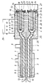
- the device shown as an exemplary embodiment has two parallel inner tubes 1 and 2 for gas extraction, which are enclosed by a common outer jacket 3 and form a structural unit resulting in two sampling probes.
- the two inner tubes 1 and 2 are each provided with a heater which is wound in the form of an electrical heating conductor 4 around the respective inner tube 1 or 2.
- the outer jacket 3 is double-walled at least in the region of the insertion length into the reaction vessel, so that in the area of the outer jacket 3 there is an outer annular space 5 for the coolant supply and an inner annular space 6 for the coolant discharge.
- the annular space 5 is consequently connected via a connecting piece 7 to a supply line and the annular space 6 to a return line 8 for the cooling liquid, usually water.
- thermal insulation 9 is provided, which prevents mutual interference between the jacket cooling and the tube heating.
- the inflow openings 11 of the two inner tubes 1 and 2 are shielded from one another by two guide walls 12, between which the temperature probe 10 protrudes into the reaction vessel.
- two axially parallel filters 13 and 14 are connected to the two sampling probes. These filters 13 and 14, which are used to separate the dust carried with the gas samples taken, essentially consist of a filter bowl 15 and a filter candle 16 which is inserted into the filter bowl leaving an annular space 17 free.
- the filter candles 16 are carried by filter bases 18, which are detachably screwed to connecting flanges 19 of the filter pots 15.
- the filter candles 16, which form the actual filter body, are fastened according to the exemplary embodiment by means of tension screws 20.
- the gas sample drawn from the reaction vessel is sucked through the filter candle 16 and fed to an analysis device via a gas line connection 21.
- the filter base 18 of the two filters 14 forms blowing nozzles in the area of the annular space 17 in the form of blowing openings 22, which start from an annular channel 23 and open into the annular space 17.
- This ring channel 23 forms a distributor line provided with a blow line connection 24, so that a blow stream can be generated through the annular space 17 of the two filters 14 against the gas extraction direction.
- the filter pots 15 are also encased with the heating conductor 4 of an electrical resistance heater and enclosed by a common outer jacket 25 which is equipped with thermal insulation 26.
- This measure effectively prevents a drop below the dew point in the area of the filter pots 15 with a comparatively small amount of energy.
- the jacket 25 is closed by a removable cover 27, through which the blow lines and the further gas lines are passed and which also with a Thermal insulation is provided, but this is not shown for reasons of clarity.
- connection box 28 The electrical supply to the heaters, the measuring lines for temperature monitoring and any control connections that may be present are combined in a connection box 28.
- the gas sample is withdrawn from the reaction vessel via one of the two inner tubes.
- the inner tube 1 is used for this purpose, the dust-laden gas is fed through the inner tube to the downstream filter 13 and extracted by the filter candle 16, the solid particles being retained in the annular space 17 between the filter bowl 15 and the filter candle 16.
- the filter 14 connected downstream of the other inner tube 2 can be cleaned, preferably with the aid of an excess amount of the gas drawn off through the inner tube 1, which is blown back into the reaction vessel through the filter 14 and the inner tube 2.
- This excess gas is introduced into the filter 14 via the blow line connection 24 in order to blow the dust in the filter bowl 15 out of the filter bowl and back through the inner tube 2 into the reaction vessel.
- the arrangement of the filter 14 in the extension of the inner tube 2 ensures an essentially straight flow path without deflections which impair cleaning, so that good cleaning is ensured without having to remove the filter candle 16 from the filter bowl 15.
- the filter candle 16 itself can also be blown out if compressed gas is also introduced into the filter 14 via the gas line connection 21.
- the dust-laden blow stream through the inner tube 2 cannot falsify the gas sample simultaneously drawn through the inner tube 1 from the reaction vessel, because through the guide walls 12 for a corresponding one Separation between the incoming and outgoing gas flows is ensured.
- this filter 13 If the proper functioning of this filter 13 is impaired by the amount of solids retained in the filter bowl 15 of the filter 13, the gas extraction is switched from the inner tube 1 to the inner tube 2 and the filter 13 is blown out in the opposite direction to the removal direction in order to be ready for a new use if the filter 14 begins to move.
- This alternating gas withdrawal through the two inner tubes 1 and 2 can thus ensure a continuous gas analysis for controlling the course of the reaction in the reaction vessel.
Landscapes
- Chemical & Material Sciences (AREA)
- Chemical Kinetics & Catalysis (AREA)
- Physics & Mathematics (AREA)
- Life Sciences & Earth Sciences (AREA)
- Health & Medical Sciences (AREA)
- Biochemistry (AREA)
- Molecular Biology (AREA)
- Analytical Chemistry (AREA)
- Biomedical Technology (AREA)
- General Health & Medical Sciences (AREA)
- General Physics & Mathematics (AREA)
- Immunology (AREA)
- Pathology (AREA)
- Engineering & Computer Science (AREA)
- Geometry (AREA)
- Sampling And Sample Adjustment (AREA)
- Devices For Use In Laboratory Experiments (AREA)
Abstract
Description
Die Erfindung bezieht sich auf eine Vorrichtung zur kontinuierlichen Entnahme heißer Gasproben aus einem Reaktionsgefäß mit zwei aus je einem beheizten Innenrohr und aus einem gegenüber dem Innenrohr wärmeisolierten, gekühlten Außenmantel bestehenden Entnahmesonden, denen je ein einen Filtertopf mit einer lösbar eingesetzten Filterkerze aufweisendes Filter nachgeordnet ist.The invention relates to a device for the continuous removal of hot gas samples from a reaction vessel with two sampling probes, each consisting of a heated inner tube and a cooled outer jacket that is insulated from the inner tube, and each of which is followed by a filter having a filter bowl with a detachably inserted filter candle.
Zur Steuerung eines Reaktionsablaufes in Abhängigkeit von der Zusammensetzung der bei diesem Reaktionsablauf entstehenden Gase ist eine Entnahme von Gasproben erforderlich. Da das Abziehen der Gasproben über eine Entnahmesonde eine kontinuierliche Probenentnahme ausschließt, weil insbesondere bei staubbeladenen Heißgasen die Entnahmesonde mit dem nachgeordneten Filter zum Abscheiden der Feststoffe in mehr oder weniger regelmäßigen Abständen gewartet werden muß, wurde bereits der Einsatz von zwei parallelgeschalteten Entnahmesonden vorgeschlagen (EP-A-O 243 569), über die abwechselnd die Gasproben dem Reaktionsgefäß entnommen werden, so daß an der jeweils nicht der Probenentnahme dienenden Entnahmesonde die erforderlichen Wartungsarbeiten durchgeführt werden können. Zur Verringerung des Wartungsaufwandes wird dabei vorteilhaft eine den Analysenbedarf übersteigende Gasmenge aus dem Reaktionsgefäß abgezogen, um mit der Überschußmenge die jeweils andere Sonde gegensinnig zur Entnahmerichtung zu durchblasen und dadurch zu reinigen. Obwohl durch diese Maßnahmen tatsächlich ein kontinuierlicher Gas analysenbetrieb aufrecht erhalten werden kann, bleiben die Wartungsanforderungen vergleichsweise hoch. Der in den den Entnahmesonden nachgeschalteten Filtern zurückgehaltene Staub muß nämlich trotz des regelmäßigen Durchblasens der Filter gegensinnig zur Entnahmerichtung von Hand aus aus den Filtertöpfen entfernt werden, weil sich aufgrund der mehrfachen Umlenkung der Blasströme Toträume ergeben, in denen sich der Staub ablagern kann. Außerdem ist mit dem Einsatz von zwei Entnahmesonden für die Gasproben ein erheblicher Mehraufwand für den Sondenanschluß am Reaktionsgefäß verbunden.In order to control a reaction sequence depending on the composition of the gases generated in this reaction sequence, gas samples must be taken. Since withdrawing the gas samples via a sampling probe precludes continuous sampling, because, particularly in the case of dust-laden hot gases, the sampling probe with the downstream filter for separating the solids has to be serviced at more or less regular intervals, the use of two sampling probes connected in parallel has already been proposed (EP- AO 243 569), via which the gas samples are taken alternately from the reaction vessel, so that the required maintenance work can be carried out on the sampling probe that is not used for taking the sample. To reduce the maintenance effort, an amount of gas which exceeds the analysis requirement is advantageously withdrawn from the reaction vessel in order to use the excess amount to blow the other probe in the opposite direction to the removal direction and thereby to clean it. Although these measures actually make it a continuous gas maintenance operations can be maintained, the maintenance requirements remain comparatively high. The dust retained in the filters downstream of the sampling probes has to be removed from the filter pots by hand in spite of the regular blow-through of the filters in the opposite direction to the removal direction, because due to the multiple deflection of the blowing streams there are dead spaces in which the dust can be deposited. In addition, the use of two sampling probes for the gas samples involves a considerable additional outlay for the probe connection to the reaction vessel.
Der Erfindung liegt somit die Aufgabe zugrunde, diese Mängel zu vermeiden und eine Vorrichtung zur kontinuierlichen Entnahme heißer Gasproben aus einem Reaktionsgefäß der eingangs geschilderten Art mit einfachen Mittels so zu verbessern, daß einerseits der Mehraufwand für den Sondenanschluß an das Reaktionsgefäß vermieden und anderseits die Wartung für die Reinigung der Filter entscheidend verringert werden kann.The invention is therefore based on the object to avoid these deficiencies and to improve a device for the continuous removal of hot gas samples from a reaction vessel of the type described above with simple means that on the one hand the additional effort for the probe connection to the reaction vessel is avoided and on the other hand the maintenance for the cleaning of the filters can be reduced significantly.
Die Erfindung löst die gestellte Aufgabe dadurch, daß die beiden nebeneinandergereihten Entnahmesonden zu einer an das Reaktionsgefäß anschließbaren Baueinheit verbunden sind, die die beiden zumindest im wesentlichen achsparallelen Filter in Verlängerung der zugehörigen Entnahmesonden umfaßt.The invention achieves the stated object in that the two sampling probes arranged side by side are connected to form a unit which can be connected to the reaction vessel and which comprises the two at least substantially axially parallel filters in extension of the associated sampling probes.
Die Verbindung der sonst voneinander getrennten Entnahmesonden zu einer Baueinheit bringt zunächst den Vorteil mit sich, daß sich der Anschlußaufwand für beide Sonden auf den üblichen Anschlußaufwand einer Sonde verringert, wobei im Reaktionsgefäß lediglich eine Sondendurchtrittsöffnung vorzusehen ist. Dazu kommt noch, daß durch die Anordnung der beiden Filter in Verlängerung der zugehörigen Entnahmesonden eine weitgehend geradlinige Blasstrecke für die Filterreinigung sichergestellt wird, so daß mit dem gegensinnigen Durchblasen der Filter und der Entnahmesonden mit der Überschuß menge der durch die jeweils andere Entnahmesonde abgezogenen Gasprobe die angestrebte Reinigung der Filter und der Entnahmesonden tatsächlich erreicht wird.The connection of the otherwise separate sampling probes to a structural unit initially has the advantage that the connection effort for both probes is reduced to the usual connection effort of one probe, only one probe passage opening having to be provided in the reaction vessel. In addition, a largely rectilinear blowing section for filter cleaning is ensured by the arrangement of the two filters in the extension of the associated sampling probes, so that with the opposite blowing through of the filters and the sampling probes with the excess amount of the gas sample drawn by the other sampling probe, the desired cleaning of the filters and the sampling probes is actually achieved.
Die beiden Entnahmesonden könnten jeweils mit einem gekühlten Außenmantel versehen sein, um der Temperaturbelastung durch die heißen Gase im Reaktionsgefäß Rechnung zu tragen. Einfachere Verhältnisse ergeben sich allerdings in weiterer Ausbildung der Erfindung dadurch, daß die beheizten Innenrohre der beiden Entnahmesonden von einem gemeinsamen, gekühlten Außenmantel umschlossen werden. Durch die gesonderte Heizung für die beiden Innenrohre kann vorteilhaft sichergestellt werden, daß keine Taupunktunterschreitung im Bereich des jeweils der Probenentnahme dienenden Innenrohres auftreten kann. Die Wärmeisolierung zwischen den Innenrohren und dem gemeinsamen Außenmantel unterbindet dabei eine gegenseitige Einflußnahme zwischen der Mantelkühlung und der Innenrohrheizung. Außerdem wird durch den gemeinsamen Außenmantel eine kompakte Baueinheit für die beiden Entnahmesonden erzielt.The two sampling probes could each be provided with a cooled outer jacket in order to take into account the temperature load caused by the hot gases in the reaction vessel. In a further development of the invention, however, simpler conditions result from the fact that the heated inner tubes of the two sampling probes are enclosed by a common, cooled outer jacket. The separate heating for the two inner tubes can advantageously ensure that the temperature does not drop below the dew point in the area of the inner tube that is used for sampling. The thermal insulation between the inner tubes and the common outer jacket prevents mutual influence between the jacket cooling and the inner tube heating. In addition, a compact structural unit for the two sampling probes is achieved through the common outer jacket.
Um eine besonders vollständige Reinigung der Filter zu erreichen, können die beiden Filter je einen die Filterkerze tragenden, an den Filtertopf anflanschbaren Filterboden aufweisen, der in den Ringraum zwischen dem Filtertopf und der Filterkerze mündende, an eine Blasleitung anschließbare Blasdüsen bildet. Über diese Blasdüsen wird eine achsparallele Blasströmung innerhalb des Ringraumes zwischen dem Filtertopf und der Filterkerze erzwungen und eine vollständige Reinigung des Filtertopfes von den zurückgehaltenen Feststoffmengen erreicht, weil ja der Blasstrom nicht zuerst durch die Filterkerze gablasen werden muß, was nicht nur mit einer Blasstromumlenkung, sondern auch mit einem entsprechenden Druckabfall verbunden ist.In order to achieve a particularly complete cleaning of the filters, the two filters can each have a filter base which supports the filter candle and can be flanged to the filter bowl and which forms blowing nozzles which open into the annular space between the filter bowl and the filter candle and can be connected to a blowing line. These blowing nozzles force an axially parallel blowing flow within the annular space between the filter bowl and the filter candle and complete cleaning of the filter bowl of the retained solids amounts is achieved because the blowing stream does not have to be blown through the filter candle first, which is not only with a blowing flow deflection, but is also associated with a corresponding pressure drop.
Damit ein über den Querschnitt des Ringraumes zwischen dem Filtertopf und der Filterkerze gleichmäßig verteilter Blasstrom innerhalb des Filtertopfes erzeugt werden kann, können die Blasdüsen in einfacher Weise aus mit einem Ringkanal verbundenen Blasöffnungen im Filterboden bestehen. Der Ringkanal bildet dabei eine Verteilerleitung, die an die Blasleitung angeschlossen wird.So that over the cross section of the annular space between the Filter cup and the filter cartridge evenly distributed blowing stream can be generated within the filter bowl, the blowing nozzles can easily consist of blow openings connected to an annular channel in the filter base. The ring channel forms a distribution line that is connected to the blow line.
Wie die Innenrohre der Entnahmesonden können auch die in Verlängerung der Innenrohre vorgesehenen Filtertöpfe von einem gemeinsamen, wärmeisolierten Mantel umschlossen werden. Dieser Mantel kann in einfacher Weise Wärmeverluste für die Heizung der Filtertöpfe vermeiden helfen, die ja ebenfalls auf einen Temperaturbereich über dem Taupunkt erwärmt werden müssen, um eine Kondensatbildung und damit eine Schlammbildung zu vermeiden.Like the inner tubes of the sampling probes, the filter pots provided in the extension of the inner tubes can be enclosed by a common, heat-insulated jacket. This jacket can help in a simple way to avoid heat losses for heating the filter pots, which must also be heated to a temperature range above the dew point in order to avoid condensation and thus sludge formation.
Die Zusammenfassung von zwei Entnahmesonden zu einer Baueinheit bildet außerdem eine vorteilhafte Voraussetzung für die Anordnung eines Temperaturfühlers zum Erfassen der Gastemperatur innerhalb des Reaktionsgefäßes. Zu diesem Zweck braucht lediglich zwischen den beiden Entnahmesonden ein in das Reaktionsgefäß ragender Temperaturfühler vorgesehen zu werden, der die Gastemperatur im Bereich der Einströmöffnungen beider Entnahmesonden erfaßt.The combination of two sampling probes into one structural unit also forms an advantageous prerequisite for the arrangement of a temperature sensor for detecting the gas temperature within the reaction vessel. For this purpose, it is only necessary to provide a temperature sensor which projects into the reaction vessel and which detects the gas temperature in the region of the inflow openings of both sampling probes between the two sampling probes.
Insbesondere bei gerade auslaufenden Einströmöffnungen der Entnahmesonden kann die Gefahr bestehen, daß beim Ausblasen der einen Entnahmesonde die durch die andere Entnahmesonde abgezogenen Gasproben durch den Blasstrom verfälscht werden. Um dieser Gefahr zu begegnen, kann zwischen den Innenrohren der beiden Entnahmesonden an dem in das Reaktionsgefäß ragendem Ende wenigstens eine die ein- bzw. austretenden Gasströmungen voneinander trennende Leitwand vorgesehen sein. Besonders vorteilhafte Verhältnisse ergeben sich, wenn beiden Innenrohren je eine Leitwand zugeordnet wird, zwischen denen dann der Temperaturfühler in das Reaktionsgefäß ragen kann. Es braucht wohl nicht besonders hervorgehoben zu werden, daß auch die Leitwände oder die Halterung bzw. die Anschlüsse des Temperaturfühlers mit einer Kühlung versehen werden können, falls dies erforderlich ist.In particular when the inlet openings of the sampling probes are just running out, there can be the risk that when one sampling probe is blown out, the gas samples drawn off by the other sampling probe are falsified by the blowing stream. In order to counter this danger, at least one guide wall separating the incoming and outgoing gas flows can be provided between the inner tubes of the two sampling probes at the end projecting into the reaction vessel. Particularly advantageous conditions result if a guide wall is assigned to each of the two inner tubes, between which the temperature sensor then projects into the reaction vessel can. It need not be particularly emphasized that the guide walls or the holder or the connections of the temperature sensor can also be provided with cooling, if this is necessary.
In der Zeichnung ist der Erfindungsgegenstand beispielsweise dargestellt, und zwar wird eine erfindungsgemäße Vorrichtung zur kontinuierlichen Entnahme heißer Gasproben aus einem Reaktionsgefäß in einem vereinfachten Axialschnitt gezeigt.The subject matter of the invention is shown in the drawing, for example, namely a device according to the invention for the continuous removal of hot gas samples from a reaction vessel is shown in a simplified axial section.
Die als Ausführungsbeispiel dargestellte Vorrichtung weist zwei parallel nebeneinander angeordnete Innenrohre 1 und 2 für die Gasentnahme auf, die von einem gemeinsamen Außenmantel 3 umschlossen werden und eine zwei Entnahmesonden ergebende Baueinheit bilden. Die beiden Innenrohre 1 und 2 sind jeweils mit einer Heizung versehen, die in Form eines elektrischen Heizleiters 4 um das jeweilige Innenrohr 1 bzw. 2 gewunden ist. Der Außenmantel 3 ist zumindest im Bereich der Einstecklänge in das Reaktionsgefäß doppelwandig ausgeführt, so daß sich im Bereich des Außenmantels 3 ein äußerer Ringraum 5 für die Kühlflüssigkeitszuführung und ein innerer Ringraum 6 für die Kühlflüssigkeitsabfuhr ergibt. Der Ringraum 5 wird demzufolge über einen Anschlußstutzen 7 an eine Zuleitung und der Ringraum 6 an eine Rückleitung 8 für die Kühlflüssigkeit, üblicherweise Wasser, angeschlossen. Zwischen dem Außemantel 3 und den beiden Innenrohren 1 und 2 ist eine Wärmeisolierung 9 vorgesehen, die eine gegenseitige Beeinflussung zwischen der Mantelkühlung und der Rohrheizung unterbindet.The device shown as an exemplary embodiment has two parallel
Zwischen den beiden Innenrohren 1 und 2 verläuft ein in das Reaktionsgefäß vorragender Temperaturfühler 10, mit dessen Hilfe die Gastemperatur im Entnahmebereich des Reaktionsgefäßes gemessen werden kann. Die Einströmöffnungen 11 der beiden Innenrohre 1 und 2 sind gegeneinander durch zwei Leitwände 12 abgeschirmt, zwischen denen der Temperatur fühler 10 in das Reaktionsgefäß ragt.Between the two
In Verlängerung der beiden Innenrohre 1 und 2 sind an die beiden Entnahmesonden zwei achsparallele Filter 13 und 14 angeschlossen. Diese Filter 13 und 14, die zum Abscheiden des mit den entnommen Gasproben mitgeführten Staubes dienen, bestehen im wesentlichen aus je einem Filtertopf 15 und einer Filterkerze 16, die unter Freilassung eines Ringraumes 17 in den Filtertopf eingesetzt ist. Die Filterkerzen 16 werden dabei von Filterböden 18 getragen, die mit Anschlußflanschen 19 der Filtertöpfe 15 lösbar verschraubt sind. Die Befestigung der Filterkerzen 16, die den eigentlichen Filterkörper bilden, erfolgt gemäß dem Ausführungsbeispiel durch Spannschrauben 20. Die aus dem Reaktionsgefäß abgezogene Gasprobe wird jeweils durch die Filterkerze 16 gesaugt und über einen Gasleitungsanschluß 21 einem Analysengerät zugeführt.In extension of the two
Der Filterboden 18 der beiden Filter 14 bildet im Bereich des Ringraumes 17 Blasdüsen in Form von Blasöffnungen 22, die von einem Ringkanal 23 ausgehen und in den Ringraum 17 münden. Dieser Ringkanal 23 bildet eine mit einem Blasleitungsanschluß 24 versehene Verteilerleitung, so daß durch den Ringraum 17 der beiden Filter 14 ein Blasstrom entgegen der Gasentnahmerichtung erzeugt werden kann.The
Wie aus der Zeichnung ersichtlich ist, sind auch die Filtertöpfe 15 mit dem Heizleiter 4 einer elektrischen Widerstandsheizung umwunden und von einem gemeinsamen Außenmantel 25 umschlossen, der mit einer Wärmeisolierung 26 ausgestattet ist. Durch diese Maßnahme kann mit einem vergleichsweise geringen Energieeinsatz eine Taupunktunterschreitung im Bereich der Filtertöpfe 15 wirksam unterbunden werden. Der Mantel 25 ist durch einen abnehmbaren Deckel 27 verschlossen, durch den die Blasleitungen und die weiterführenden Gasleitungen hindurchgeführt werden und der ebenfalls mit einer Wärmeisolierung versehen wird, was jedoch aus Übersichtlichkeitsgründen nicht dargestellt ist.As can be seen from the drawing, the
Die elektrische Versorgung der Heizungen, die Meßleitungen für die Temperaturüberwachung und allenfalls vorhandene Steueranschlüsse sind in einem Anschlußkasten 28 zusammengefaßt.The electrical supply to the heaters, the measuring lines for temperature monitoring and any control connections that may be present are combined in a
Um eine kontinuierliche Entnahme einer Gasprobe aus einem Reaktionsgefäß sicherzustellen, wird über eines der beiden Innenrohre die Gasprobe aus dem Reaktionsgefäß abgezogen. Wird hiefür beispielsweise das Innenrohr 1 eingesetzt, so wird das staubbeladene Gas durch das Innenrohr dem nachgeordneten Filter 13 zugeführt und durch die Filterkerze 16 abgesaugt, wobei die Feststoffteilchen im Ringraum 17 zwischen dem Filtertopf 15 und der Filterkerze 16 zurückgehalten werden. Gleichzeitig kann das dem anderen Innenrohr 2 nachgeschaltete Filter 14 gereinigt werden, und zwar vorzugsweise mit Hilfe einer Überschußmenge an dem durch das Innenrohr 1 abgezogenen Gases, das durch das Filter 14 und das Innenrohr 2 in das Reaktionsgefäß zurückgeblasen wird. Die Einleitung dieses Überschußgases in das Filter 14 erfolgt über den Blasleitungsanschluß 24, um den im Filtertopf 15 befindlichen Staub aus dem Filtertopf heraus und durch das Innenrohr 2 in das Reaktionsgefäß zurückzublasen. Die Anordnung des Filters 14 in Verlängerung des Innenrohres 2 stellt dabei einen im wesentlichen geraden Strömungsweg ohne die Reinigung beeinträchtigende Umlenkungen sicher, so daß für eine gute Reinigung gesorgt wird, ohne die Filterkerze 16 aus dem Filtertopf 15 entnehmen zu müssen. Die Filterkerze 16 selbst kann ebenfalls ausgeblasen werden, wenn Druckgas auch über den Gasleitungsanschluß 21 in das Filter 14 eingeleitet wird. Der staubbeladene Blasstrom durch das Innenrohr 2 kann die gleichzeitig durch das Innenrohr 1 aus dem Reaktionsgefäß abgezogene Gasprobe nicht verfälschen, weil durch die Leitwände 12 für eine entsprechende Trennung zwischen den ein- bzw. austretenden Gasströmungen gesorgt wird.In order to ensure that a gas sample is continuously taken from a reaction vessel, the gas sample is withdrawn from the reaction vessel via one of the two inner tubes. If, for example, the inner tube 1 is used for this purpose, the dust-laden gas is fed through the inner tube to the
Wird durch die im Filtertopf 15 des Filters 13 zurückgehaltene Feststoffmenge die einwandfreie Funktion dieses Filters 13 beeinträchtigt, so wird die Gasentnahme vom Innenrohr 1 auf das Innenrohr 2 umgeschaltet und das Filter 13 gegensinnig zur Entnahmerichtung ausgeblasen, um für einen neuerlichen Einsatz bereit zu sein, wenn sich das Filter 14 zu verlegen beginnt. Durch diese abwechselnde Gasentnahme durch die beiden Innenrohre 1 und 2 kann somit eine kontinuierliche Gasanalyse für die Steuerung des Reaktionsablaufes im Reaktionsgefäß gewährleistet werden.If the proper functioning of this
Claims (7)
Priority Applications (8)
| Application Number | Priority Date | Filing Date | Title |
|---|---|---|---|
| ES198888890004T ES2033016T3 (en) | 1988-01-11 | 1988-01-11 | DEVICE FOR THE CONTINUOUS TAKING OF HOT GAS SAMPLES FROM A REACTION CONTAINER. |
| AT88890004T ATE76193T1 (en) | 1988-01-11 | 1988-01-11 | DEVICE FOR CONTINUOUS TAKING OF HOT GAS SAMPLES FROM A REACTION VESSEL. |
| DE8888890004T DE3871121D1 (en) | 1988-01-11 | 1988-01-11 | DEVICE FOR CONTINUOUSLY TAKING HOT GAS SAMPLES FROM A REACTION TUBE. |
| EP88890004A EP0324331B1 (en) | 1988-01-11 | 1988-01-11 | Apparatus for continuous hot gas sampling from a reactor |
| CA000587452A CA1311627C (en) | 1988-01-11 | 1989-01-04 | Apparatus for extracting hot gas samples from a reaction vessel |
| US07/296,220 US5039322A (en) | 1988-01-11 | 1989-01-10 | Apparatus for extracting hot gas samples from a reaction vessel |
| JP1004557A JPH01232231A (en) | 1988-01-11 | 1989-01-10 | Takeoff apparatus for hot gas sample from reaction container |
| SE8900065A SE465290B (en) | 1988-01-11 | 1989-01-10 | DEVICE FOR SAMPLING HOT GAS SAMPLES FROM A REACTION BOARD |
Applications Claiming Priority (1)
| Application Number | Priority Date | Filing Date | Title |
|---|---|---|---|
| EP88890004A EP0324331B1 (en) | 1988-01-11 | 1988-01-11 | Apparatus for continuous hot gas sampling from a reactor |
Publications (2)
| Publication Number | Publication Date |
|---|---|
| EP0324331A1 true EP0324331A1 (en) | 1989-07-19 |
| EP0324331B1 EP0324331B1 (en) | 1992-05-13 |
Family
ID=8200702
Family Applications (1)
| Application Number | Title | Priority Date | Filing Date |
|---|---|---|---|
| EP88890004A Expired - Lifetime EP0324331B1 (en) | 1988-01-11 | 1988-01-11 | Apparatus for continuous hot gas sampling from a reactor |
Country Status (4)
| Country | Link |
|---|---|
| EP (1) | EP0324331B1 (en) |
| AT (1) | ATE76193T1 (en) |
| DE (1) | DE3871121D1 (en) |
| ES (1) | ES2033016T3 (en) |
Cited By (7)
| Publication number | Priority date | Publication date | Assignee | Title |
|---|---|---|---|---|
| DE4111377A1 (en) * | 1991-04-09 | 1992-10-22 | M & C Products | Gas sampling probe - has exchangeable gas filter fitted to removable lid of probe housing |
| DE4216404A1 (en) * | 1992-05-18 | 1993-11-25 | Testoterm Mestechnik Gmbh & Co | Gas sampling device for a flue gas analyzer |
| DE19850082B4 (en) * | 1998-10-30 | 2006-11-09 | Harry Kampmann | Arrangement of a flue gas sampling probe |
| CN107727456A (en) * | 2017-11-08 | 2018-02-23 | 上海北分科技股份有限公司 | A kind of novel flange |
| CN112955740A (en) * | 2018-11-15 | 2021-06-11 | 霍尔辛姆科技有限公司 | Method and apparatus for analyzing gas samples in rotary cement kilns |
| CN114624070A (en) * | 2022-03-02 | 2022-06-14 | 杭州绰美科技有限公司 | Flue gas sampling probe device and back flushing method thereof |
| CN116571026A (en) * | 2023-05-25 | 2023-08-11 | 厦门韫茂科技有限公司 | A self-cleaning filter device and its self-cleaning process |
Families Citing this family (1)
| Publication number | Priority date | Publication date | Assignee | Title |
|---|---|---|---|---|
| CN112057962A (en) * | 2020-09-15 | 2020-12-11 | 山东光测环境科技有限公司 | A leading filter for flue gas analysis |
Citations (5)
| Publication number | Priority date | Publication date | Assignee | Title |
|---|---|---|---|---|
| DE2301254A1 (en) * | 1972-01-12 | 1973-07-26 | Lucas Aerospace Ltd | REVERSIBLE TURBINE |
| US3748906A (en) * | 1970-10-15 | 1973-07-31 | Jones & Laughlin Steel Corp | Gas sampling apparatus |
| FR2363792A1 (en) * | 1976-09-06 | 1978-03-31 | Acec | Analyser for detecting oxygen, carbon monoxide and methane - for continuous reliable operation at output of cementing furnace |
| EP0095802A1 (en) * | 1982-05-28 | 1983-12-07 | CENTRE DE RECHERCHES METALLURGIQUES CENTRUM VOOR RESEARCH IN DE METALLURGIE Association sans but lucratif | Gas sampling devices |
| EP0243569A1 (en) * | 1986-04-29 | 1987-11-04 | VOEST-ALPINE INDUSTRIEANLAGENBAU GESELLSCHAFT m.b.H. | Method and apparatus for continuous hot gas sampling for analysis in a reactor |
Family Cites Families (2)
| Publication number | Priority date | Publication date | Assignee | Title |
|---|---|---|---|---|
| DE2301264A1 (en) * | 1973-01-11 | 1974-07-25 | Polysius Ag | Device for extracting dust containing gas samples - having double channel probe and solenoid valve arrangement for backflushing |
| GB8520273D0 (en) * | 1985-08-13 | 1985-09-18 | Smidth & Co As F L | Extracting sample from gas flow |
-
1988
- 1988-01-11 EP EP88890004A patent/EP0324331B1/en not_active Expired - Lifetime
- 1988-01-11 DE DE8888890004T patent/DE3871121D1/en not_active Expired - Lifetime
- 1988-01-11 AT AT88890004T patent/ATE76193T1/en not_active IP Right Cessation
- 1988-01-11 ES ES198888890004T patent/ES2033016T3/en not_active Expired - Lifetime
Patent Citations (5)
| Publication number | Priority date | Publication date | Assignee | Title |
|---|---|---|---|---|
| US3748906A (en) * | 1970-10-15 | 1973-07-31 | Jones & Laughlin Steel Corp | Gas sampling apparatus |
| DE2301254A1 (en) * | 1972-01-12 | 1973-07-26 | Lucas Aerospace Ltd | REVERSIBLE TURBINE |
| FR2363792A1 (en) * | 1976-09-06 | 1978-03-31 | Acec | Analyser for detecting oxygen, carbon monoxide and methane - for continuous reliable operation at output of cementing furnace |
| EP0095802A1 (en) * | 1982-05-28 | 1983-12-07 | CENTRE DE RECHERCHES METALLURGIQUES CENTRUM VOOR RESEARCH IN DE METALLURGIE Association sans but lucratif | Gas sampling devices |
| EP0243569A1 (en) * | 1986-04-29 | 1987-11-04 | VOEST-ALPINE INDUSTRIEANLAGENBAU GESELLSCHAFT m.b.H. | Method and apparatus for continuous hot gas sampling for analysis in a reactor |
Cited By (8)
| Publication number | Priority date | Publication date | Assignee | Title |
|---|---|---|---|---|
| DE4111377A1 (en) * | 1991-04-09 | 1992-10-22 | M & C Products | Gas sampling probe - has exchangeable gas filter fitted to removable lid of probe housing |
| DE4216404A1 (en) * | 1992-05-18 | 1993-11-25 | Testoterm Mestechnik Gmbh & Co | Gas sampling device for a flue gas analyzer |
| DE19850082B4 (en) * | 1998-10-30 | 2006-11-09 | Harry Kampmann | Arrangement of a flue gas sampling probe |
| CN107727456A (en) * | 2017-11-08 | 2018-02-23 | 上海北分科技股份有限公司 | A kind of novel flange |
| CN112955740A (en) * | 2018-11-15 | 2021-06-11 | 霍尔辛姆科技有限公司 | Method and apparatus for analyzing gas samples in rotary cement kilns |
| US12066361B2 (en) | 2018-11-15 | 2024-08-20 | Holcim Technology Ltd | Method for analyzing samples of a gas in a rotary cement kiln |
| CN114624070A (en) * | 2022-03-02 | 2022-06-14 | 杭州绰美科技有限公司 | Flue gas sampling probe device and back flushing method thereof |
| CN116571026A (en) * | 2023-05-25 | 2023-08-11 | 厦门韫茂科技有限公司 | A self-cleaning filter device and its self-cleaning process |
Also Published As
| Publication number | Publication date |
|---|---|
| ATE76193T1 (en) | 1992-05-15 |
| EP0324331B1 (en) | 1992-05-13 |
| ES2033016T3 (en) | 1993-03-01 |
| DE3871121D1 (en) | 1992-06-17 |
Similar Documents
| Publication | Publication Date | Title |
|---|---|---|
| EP0243569B1 (en) | Method and apparatus for continuous hot gas sampling for analysis in a reactor | |
| EP2191882B1 (en) | Method and device for calculating the separation level and/or carrying out a leak test in a filter assembly | |
| EP0582066B1 (en) | Process for monitoring filter elements | |
| DE4430378C2 (en) | Sampling and measuring system for determining the dust content in an exhaust duct | |
| EP0324330B1 (en) | Apparatus for hot gas sampling from a reactor | |
| DE4035242A1 (en) | OPERATIONAL MONITORING OF A TUBE CONDENSER WITH MEASUREMENTS ON SELECTED TUBES | |
| EP0324331B1 (en) | Apparatus for continuous hot gas sampling from a reactor | |
| DE3422062A1 (en) | METHOD FOR THE LONG-TERM DETERMINATION AND PERMANENT MONITORING OF THE POLLUTANT CONTENT OF SOLID-LOADED EXHAUST FLOWS | |
| EP0586798B1 (en) | Device for filtering hot dust loaden gases | |
| DE19850082B4 (en) | Arrangement of a flue gas sampling probe | |
| DE2747619B2 (en) | ||
| DD148172A3 (en) | METHOD AND ARRANGEMENT FOR CONTINUOUS SAMPLING OF RAW GASES | |
| DE4100363A1 (en) | Flue gas analyser probe installed external to flue duct with preheating gas flow - has probe head in test chamber with sampling pipework connecting funnel system | |
| WO1987007179A1 (en) | Process and device for monitoring the flow of a gaz emerging from a filter | |
| DE2539834A1 (en) | DEVICE FOR EXAMINING THE FLAMMABILITY OF A SAMPLE | |
| DE2102368C3 (en) | Device for generating a gas mixture containing hydrogen and carbon monoxide | |
| DE19527557B4 (en) | Process and apparatus for the purification of gases | |
| DE2460122A1 (en) | Gas sample removal probe at high temperatures - uses water to suck sampled gas through probe | |
| EP0583558B1 (en) | Filter elements monitoring device | |
| DE2836345A1 (en) | SOOT PRODUCTION PLANT | |
| DE4335655C1 (en) | Device for withdrawing and processing flue gas | |
| EP0292598A1 (en) | Probe device for the removal of gas from a rotating pipe cement oven | |
| DE19727969A1 (en) | Sampling system for particle bonded and filterable metallic-metalloid emissions | |
| DE4111377C2 (en) | ||
| DE2701148C3 (en) | Use of diagonally or vertically arranged heat exchangers for water-free tar removal and dedusting of hot generator raw gas and for heating generator clean gas |
Legal Events
| Date | Code | Title | Description |
|---|---|---|---|
| PUAI | Public reference made under article 153(3) epc to a published international application that has entered the european phase |
Free format text: ORIGINAL CODE: 0009012 |
|
| AK | Designated contracting states |
Kind code of ref document: A1 Designated state(s): AT BE CH DE ES FR GB IT LI |
|
| 17P | Request for examination filed |
Effective date: 19890614 |
|
| 17Q | First examination report despatched |
Effective date: 19910228 |
|
| GRAA | (expected) grant |
Free format text: ORIGINAL CODE: 0009210 |
|
| AK | Designated contracting states |
Kind code of ref document: B1 Designated state(s): AT BE CH DE ES FR GB IT LI |
|
| REF | Corresponds to: |
Ref document number: 76193 Country of ref document: AT Date of ref document: 19920515 Kind code of ref document: T |
|
| REF | Corresponds to: |
Ref document number: 3871121 Country of ref document: DE Date of ref document: 19920617 |
|
| ITF | It: translation for a ep patent filed | ||
| GBT | Gb: translation of ep patent filed (gb section 77(6)(a)/1977) | ||
| ET | Fr: translation filed | ||
| REG | Reference to a national code |
Ref country code: ES Ref legal event code: FG2A Ref document number: 2033016 Country of ref document: ES Kind code of ref document: T3 |
|
| PLBE | No opposition filed within time limit |
Free format text: ORIGINAL CODE: 0009261 |
|
| STAA | Information on the status of an ep patent application or granted ep patent |
Free format text: STATUS: NO OPPOSITION FILED WITHIN TIME LIMIT |
|
| 26N | No opposition filed | ||
| PGFP | Annual fee paid to national office [announced via postgrant information from national office to epo] |
Ref country code: GB Payment date: 19981211 Year of fee payment: 12 |
|
| PGFP | Annual fee paid to national office [announced via postgrant information from national office to epo] |
Ref country code: FR Payment date: 19981215 Year of fee payment: 12 |
|
| PGFP | Annual fee paid to national office [announced via postgrant information from national office to epo] |
Ref country code: DE Payment date: 19981217 Year of fee payment: 12 |
|
| PGFP | Annual fee paid to national office [announced via postgrant information from national office to epo] |
Ref country code: AT Payment date: 19981228 Year of fee payment: 12 |
|
| PGFP | Annual fee paid to national office [announced via postgrant information from national office to epo] |
Ref country code: CH Payment date: 19981229 Year of fee payment: 12 |
|
| PGFP | Annual fee paid to national office [announced via postgrant information from national office to epo] |
Ref country code: BE Payment date: 19990111 Year of fee payment: 12 |
|
| PGFP | Annual fee paid to national office [announced via postgrant information from national office to epo] |
Ref country code: ES Payment date: 19990119 Year of fee payment: 12 |
|
| PG25 | Lapsed in a contracting state [announced via postgrant information from national office to epo] |
Ref country code: GB Free format text: LAPSE BECAUSE OF NON-PAYMENT OF DUE FEES Effective date: 20000111 Ref country code: AT Free format text: LAPSE BECAUSE OF NON-PAYMENT OF DUE FEES Effective date: 20000111 |
|
| PG25 | Lapsed in a contracting state [announced via postgrant information from national office to epo] |
Ref country code: ES Free format text: LAPSE BECAUSE OF NON-PAYMENT OF DUE FEES Effective date: 20000112 |
|
| PG25 | Lapsed in a contracting state [announced via postgrant information from national office to epo] |
Ref country code: LI Free format text: LAPSE BECAUSE OF NON-PAYMENT OF DUE FEES Effective date: 20000131 Ref country code: CH Free format text: LAPSE BECAUSE OF NON-PAYMENT OF DUE FEES Effective date: 20000131 Ref country code: BE Free format text: LAPSE BECAUSE OF NON-PAYMENT OF DUE FEES Effective date: 20000131 |
|
| BERE | Be: lapsed |
Owner name: VOEST-ALPINE INDUSTRIEANLAGENBAU G.M.B.H. Effective date: 20000131 |
|
| GBPC | Gb: european patent ceased through non-payment of renewal fee |
Effective date: 20000111 |
|
| REG | Reference to a national code |
Ref country code: CH Ref legal event code: PL |
|
| PG25 | Lapsed in a contracting state [announced via postgrant information from national office to epo] |
Ref country code: FR Free format text: LAPSE BECAUSE OF NON-PAYMENT OF DUE FEES Effective date: 20000929 |
|
| PG25 | Lapsed in a contracting state [announced via postgrant information from national office to epo] |
Ref country code: DE Free format text: LAPSE BECAUSE OF NON-PAYMENT OF DUE FEES Effective date: 20001101 |
|
| REG | Reference to a national code |
Ref country code: FR Ref legal event code: ST |
|
| REG | Reference to a national code |
Ref country code: ES Ref legal event code: FD2A Effective date: 20010910 |
|
| PG25 | Lapsed in a contracting state [announced via postgrant information from national office to epo] |
Ref country code: IT Free format text: LAPSE BECAUSE OF NON-PAYMENT OF DUE FEES;WARNING: LAPSES OF ITALIAN PATENTS WITH EFFECTIVE DATE BEFORE 2007 MAY HAVE OCCURRED AT ANY TIME BEFORE 2007. THE CORRECT EFFECTIVE DATE MAY BE DIFFERENT FROM THE ONE RECORDED. Effective date: 20050111 |