EP0324331A1 - Dispositif de prélèvement en continu d'échantillons de gaz chauds dans un réacteur - Google Patents
Dispositif de prélèvement en continu d'échantillons de gaz chauds dans un réacteur Download PDFInfo
- Publication number
- EP0324331A1 EP0324331A1 EP88890004A EP88890004A EP0324331A1 EP 0324331 A1 EP0324331 A1 EP 0324331A1 EP 88890004 A EP88890004 A EP 88890004A EP 88890004 A EP88890004 A EP 88890004A EP 0324331 A1 EP0324331 A1 EP 0324331A1
- Authority
- EP
- European Patent Office
- Prior art keywords
- filter
- reaction vessel
- sampling probes
- inner tube
- filters
- Prior art date
- Legal status (The legal status is an assumption and is not a legal conclusion. Google has not performed a legal analysis and makes no representation as to the accuracy of the status listed.)
- Granted
Links
- 238000005070 sampling Methods 0.000 title claims abstract description 37
- 239000000523 sample Substances 0.000 claims abstract description 49
- 238000004140 cleaning Methods 0.000 abstract description 8
- 239000007789 gas Substances 0.000 description 35
- 238000007664 blowing Methods 0.000 description 14
- 238000010438 heat treatment Methods 0.000 description 6
- 238000012423 maintenance Methods 0.000 description 5
- 239000000428 dust Substances 0.000 description 4
- 238000009413 insulation Methods 0.000 description 4
- 230000000717 retained effect Effects 0.000 description 4
- 239000007787 solid Substances 0.000 description 4
- 238000001816 cooling Methods 0.000 description 3
- 238000000605 extraction Methods 0.000 description 3
- 238000004458 analytical method Methods 0.000 description 2
- 239000004020 conductor Substances 0.000 description 2
- 239000002826 coolant Substances 0.000 description 2
- 230000015572 biosynthetic process Effects 0.000 description 1
- 238000009833 condensation Methods 0.000 description 1
- 230000005494 condensation Effects 0.000 description 1
- 239000000110 cooling liquid Substances 0.000 description 1
- 230000007812 deficiency Effects 0.000 description 1
- 238000004868 gas analysis Methods 0.000 description 1
- 230000001771 impaired effect Effects 0.000 description 1
- 238000003780 insertion Methods 0.000 description 1
- 230000037431 insertion Effects 0.000 description 1
- 238000012544 monitoring process Methods 0.000 description 1
- 239000002245 particle Substances 0.000 description 1
- 238000000926 separation method Methods 0.000 description 1
- 239000010802 sludge Substances 0.000 description 1
- XLYOFNOQVPJJNP-UHFFFAOYSA-N water Substances O XLYOFNOQVPJJNP-UHFFFAOYSA-N 0.000 description 1
Images
Classifications
-
- B—PERFORMING OPERATIONS; TRANSPORTING
- B01—PHYSICAL OR CHEMICAL PROCESSES OR APPARATUS IN GENERAL
- B01D—SEPARATION
- B01D46/00—Filters or filtering processes specially modified for separating dispersed particles from gases or vapours
- B01D46/42—Auxiliary equipment or operation thereof
- B01D46/4263—Means for active heating or cooling
-
- B—PERFORMING OPERATIONS; TRANSPORTING
- B01—PHYSICAL OR CHEMICAL PROCESSES OR APPARATUS IN GENERAL
- B01D—SEPARATION
- B01D46/00—Filters or filtering processes specially modified for separating dispersed particles from gases or vapours
- B01D46/24—Particle separators, e.g. dust precipitators, using rigid hollow filter bodies
- B01D46/2403—Particle separators, e.g. dust precipitators, using rigid hollow filter bodies characterised by the physical shape or structure of the filtering element
- B01D46/2407—Filter candles
-
- B—PERFORMING OPERATIONS; TRANSPORTING
- B01—PHYSICAL OR CHEMICAL PROCESSES OR APPARATUS IN GENERAL
- B01D—SEPARATION
- B01D46/00—Filters or filtering processes specially modified for separating dispersed particles from gases or vapours
- B01D46/56—Filters or filtering processes specially modified for separating dispersed particles from gases or vapours with multiple filtering elements, characterised by their mutual disposition
- B01D46/58—Filters or filtering processes specially modified for separating dispersed particles from gases or vapours with multiple filtering elements, characterised by their mutual disposition connected in parallel
-
- G—PHYSICS
- G01—MEASURING; TESTING
- G01N—INVESTIGATING OR ANALYSING MATERIALS BY DETERMINING THEIR CHEMICAL OR PHYSICAL PROPERTIES
- G01N1/00—Sampling; Preparing specimens for investigation
- G01N1/02—Devices for withdrawing samples
- G01N1/22—Devices for withdrawing samples in the gaseous state
- G01N1/2247—Sampling from a flowing stream of gas
- G01N1/2258—Sampling from a flowing stream of gas in a stack or chimney
-
- B—PERFORMING OPERATIONS; TRANSPORTING
- B01—PHYSICAL OR CHEMICAL PROCESSES OR APPARATUS IN GENERAL
- B01D—SEPARATION
- B01D2273/00—Operation of filters specially adapted for separating dispersed particles from gases or vapours
- B01D2273/20—High temperature filtration
-
- G—PHYSICS
- G01—MEASURING; TESTING
- G01N—INVESTIGATING OR ANALYSING MATERIALS BY DETERMINING THEIR CHEMICAL OR PHYSICAL PROPERTIES
- G01N1/00—Sampling; Preparing specimens for investigation
- G01N1/02—Devices for withdrawing samples
- G01N1/22—Devices for withdrawing samples in the gaseous state
- G01N1/2202—Devices for withdrawing samples in the gaseous state involving separation of sample components during sampling
- G01N1/2205—Devices for withdrawing samples in the gaseous state involving separation of sample components during sampling with filters
-
- G—PHYSICS
- G01—MEASURING; TESTING
- G01N—INVESTIGATING OR ANALYSING MATERIALS BY DETERMINING THEIR CHEMICAL OR PHYSICAL PROPERTIES
- G01N1/00—Sampling; Preparing specimens for investigation
- G01N1/02—Devices for withdrawing samples
- G01N1/22—Devices for withdrawing samples in the gaseous state
- G01N1/2247—Sampling from a flowing stream of gas
- G01N1/2258—Sampling from a flowing stream of gas in a stack or chimney
- G01N2001/2261—Sampling from a flowing stream of gas in a stack or chimney preventing condensation (heating lines)
Definitions
- the invention relates to a device for the continuous removal of hot gas samples from a reaction vessel with two sampling probes, each consisting of a heated inner tube and a cooled outer jacket that is insulated from the inner tube, and each of which is followed by a filter having a filter bowl with a detachably inserted filter candle.
- the invention is therefore based on the object to avoid these deficiencies and to improve a device for the continuous removal of hot gas samples from a reaction vessel of the type described above with simple means that on the one hand the additional effort for the probe connection to the reaction vessel is avoided and on the other hand the maintenance for the cleaning of the filters can be reduced significantly.
- the invention achieves the stated object in that the two sampling probes arranged side by side are connected to form a unit which can be connected to the reaction vessel and which comprises the two at least substantially axially parallel filters in extension of the associated sampling probes.
- connection of the otherwise separate sampling probes to a structural unit initially has the advantage that the connection effort for both probes is reduced to the usual connection effort of one probe, only one probe passage opening having to be provided in the reaction vessel.
- a largely rectilinear blowing section for filter cleaning is ensured by the arrangement of the two filters in the extension of the associated sampling probes, so that with the opposite blowing through of the filters and the sampling probes with the excess amount of the gas sample drawn by the other sampling probe, the desired cleaning of the filters and the sampling probes is actually achieved.
- the two sampling probes could each be provided with a cooled outer jacket in order to take into account the temperature load caused by the hot gases in the reaction vessel.
- simpler conditions result from the fact that the heated inner tubes of the two sampling probes are enclosed by a common, cooled outer jacket.
- the separate heating for the two inner tubes can advantageously ensure that the temperature does not drop below the dew point in the area of the inner tube that is used for sampling.
- the thermal insulation between the inner tubes and the common outer jacket prevents mutual influence between the jacket cooling and the inner tube heating.
- a compact structural unit for the two sampling probes is achieved through the common outer jacket.
- the two filters can each have a filter base which supports the filter candle and can be flanged to the filter bowl and which forms blowing nozzles which open into the annular space between the filter bowl and the filter candle and can be connected to a blowing line.
- blowing nozzles force an axially parallel blowing flow within the annular space between the filter bowl and the filter candle and complete cleaning of the filter bowl of the retained solids amounts is achieved because the blowing stream does not have to be blown through the filter candle first, which is not only with a blowing flow deflection, but is also associated with a corresponding pressure drop.
- the blowing nozzles can easily consist of blow openings connected to an annular channel in the filter base.
- the ring channel forms a distribution line that is connected to the blow line.
- the filter pots provided in the extension of the inner tubes can be enclosed by a common, heat-insulated jacket.
- This jacket can help in a simple way to avoid heat losses for heating the filter pots, which must also be heated to a temperature range above the dew point in order to avoid condensation and thus sludge formation.
- the combination of two sampling probes into one structural unit also forms an advantageous prerequisite for the arrangement of a temperature sensor for detecting the gas temperature within the reaction vessel.
- a temperature sensor for detecting the gas temperature within the reaction vessel.
- At least one guide wall separating the incoming and outgoing gas flows can be provided between the inner tubes of the two sampling probes at the end projecting into the reaction vessel.
- a guide wall is assigned to each of the two inner tubes, between which the temperature sensor then projects into the reaction vessel can. It need not be particularly emphasized that the guide walls or the holder or the connections of the temperature sensor can also be provided with cooling, if this is necessary.
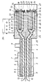
- the device shown as an exemplary embodiment has two parallel inner tubes 1 and 2 for gas extraction, which are enclosed by a common outer jacket 3 and form a structural unit resulting in two sampling probes.
- the two inner tubes 1 and 2 are each provided with a heater which is wound in the form of an electrical heating conductor 4 around the respective inner tube 1 or 2.
- the outer jacket 3 is double-walled at least in the region of the insertion length into the reaction vessel, so that in the area of the outer jacket 3 there is an outer annular space 5 for the coolant supply and an inner annular space 6 for the coolant discharge.
- the annular space 5 is consequently connected via a connecting piece 7 to a supply line and the annular space 6 to a return line 8 for the cooling liquid, usually water.
- thermal insulation 9 is provided, which prevents mutual interference between the jacket cooling and the tube heating.
- the inflow openings 11 of the two inner tubes 1 and 2 are shielded from one another by two guide walls 12, between which the temperature probe 10 protrudes into the reaction vessel.
- two axially parallel filters 13 and 14 are connected to the two sampling probes. These filters 13 and 14, which are used to separate the dust carried with the gas samples taken, essentially consist of a filter bowl 15 and a filter candle 16 which is inserted into the filter bowl leaving an annular space 17 free.
- the filter candles 16 are carried by filter bases 18, which are detachably screwed to connecting flanges 19 of the filter pots 15.
- the filter candles 16, which form the actual filter body, are fastened according to the exemplary embodiment by means of tension screws 20.
- the gas sample drawn from the reaction vessel is sucked through the filter candle 16 and fed to an analysis device via a gas line connection 21.
- the filter base 18 of the two filters 14 forms blowing nozzles in the area of the annular space 17 in the form of blowing openings 22, which start from an annular channel 23 and open into the annular space 17.
- This ring channel 23 forms a distributor line provided with a blow line connection 24, so that a blow stream can be generated through the annular space 17 of the two filters 14 against the gas extraction direction.
- the filter pots 15 are also encased with the heating conductor 4 of an electrical resistance heater and enclosed by a common outer jacket 25 which is equipped with thermal insulation 26.
- This measure effectively prevents a drop below the dew point in the area of the filter pots 15 with a comparatively small amount of energy.
- the jacket 25 is closed by a removable cover 27, through which the blow lines and the further gas lines are passed and which also with a Thermal insulation is provided, but this is not shown for reasons of clarity.
- connection box 28 The electrical supply to the heaters, the measuring lines for temperature monitoring and any control connections that may be present are combined in a connection box 28.
- the gas sample is withdrawn from the reaction vessel via one of the two inner tubes.
- the inner tube 1 is used for this purpose, the dust-laden gas is fed through the inner tube to the downstream filter 13 and extracted by the filter candle 16, the solid particles being retained in the annular space 17 between the filter bowl 15 and the filter candle 16.
- the filter 14 connected downstream of the other inner tube 2 can be cleaned, preferably with the aid of an excess amount of the gas drawn off through the inner tube 1, which is blown back into the reaction vessel through the filter 14 and the inner tube 2.
- This excess gas is introduced into the filter 14 via the blow line connection 24 in order to blow the dust in the filter bowl 15 out of the filter bowl and back through the inner tube 2 into the reaction vessel.
- the arrangement of the filter 14 in the extension of the inner tube 2 ensures an essentially straight flow path without deflections which impair cleaning, so that good cleaning is ensured without having to remove the filter candle 16 from the filter bowl 15.
- the filter candle 16 itself can also be blown out if compressed gas is also introduced into the filter 14 via the gas line connection 21.
- the dust-laden blow stream through the inner tube 2 cannot falsify the gas sample simultaneously drawn through the inner tube 1 from the reaction vessel, because through the guide walls 12 for a corresponding one Separation between the incoming and outgoing gas flows is ensured.
- this filter 13 If the proper functioning of this filter 13 is impaired by the amount of solids retained in the filter bowl 15 of the filter 13, the gas extraction is switched from the inner tube 1 to the inner tube 2 and the filter 13 is blown out in the opposite direction to the removal direction in order to be ready for a new use if the filter 14 begins to move.
- This alternating gas withdrawal through the two inner tubes 1 and 2 can thus ensure a continuous gas analysis for controlling the course of the reaction in the reaction vessel.
Landscapes
- Chemical & Material Sciences (AREA)
- Chemical Kinetics & Catalysis (AREA)
- Physics & Mathematics (AREA)
- Life Sciences & Earth Sciences (AREA)
- Health & Medical Sciences (AREA)
- Biochemistry (AREA)
- Molecular Biology (AREA)
- Analytical Chemistry (AREA)
- Biomedical Technology (AREA)
- General Health & Medical Sciences (AREA)
- General Physics & Mathematics (AREA)
- Immunology (AREA)
- Pathology (AREA)
- Engineering & Computer Science (AREA)
- Geometry (AREA)
- Sampling And Sample Adjustment (AREA)
- Devices For Use In Laboratory Experiments (AREA)
Priority Applications (8)
| Application Number | Priority Date | Filing Date | Title |
|---|---|---|---|
| ES198888890004T ES2033016T3 (es) | 1988-01-11 | 1988-01-11 | Dispositivo para la toma continua de muestras de gas caliente de un recipiente de reaccion. |
| AT88890004T ATE76193T1 (de) | 1988-01-11 | 1988-01-11 | Vorrichtung zur kontinuierlichen entnahme heisser gasproben aus einem reaktionsgefaess. |
| DE8888890004T DE3871121D1 (de) | 1988-01-11 | 1988-01-11 | Vorrichtung zur kontinuierlichen entnahme heisser gasproben aus einem reaktionsgefaess. |
| EP88890004A EP0324331B1 (fr) | 1988-01-11 | 1988-01-11 | Dispositif de prélèvement en continu d'échantillons de gaz chauds dans un réacteur |
| CA000587452A CA1311627C (fr) | 1988-01-11 | 1989-01-04 | Appareil de prelevement d'echantillons de gaz chauds dans une cuve a reaction |
| US07/296,220 US5039322A (en) | 1988-01-11 | 1989-01-10 | Apparatus for extracting hot gas samples from a reaction vessel |
| JP1004557A JPH01232231A (ja) | 1988-01-11 | 1989-01-10 | 反応容器からの熱い気体試料の取出装置 |
| SE8900065A SE465290B (sv) | 1988-01-11 | 1989-01-10 | Anordning foer uttag av varma gasprover ur ett reaktionskaerl |
Applications Claiming Priority (1)
| Application Number | Priority Date | Filing Date | Title |
|---|---|---|---|
| EP88890004A EP0324331B1 (fr) | 1988-01-11 | 1988-01-11 | Dispositif de prélèvement en continu d'échantillons de gaz chauds dans un réacteur |
Publications (2)
| Publication Number | Publication Date |
|---|---|
| EP0324331A1 true EP0324331A1 (fr) | 1989-07-19 |
| EP0324331B1 EP0324331B1 (fr) | 1992-05-13 |
Family
ID=8200702
Family Applications (1)
| Application Number | Title | Priority Date | Filing Date |
|---|---|---|---|
| EP88890004A Expired - Lifetime EP0324331B1 (fr) | 1988-01-11 | 1988-01-11 | Dispositif de prélèvement en continu d'échantillons de gaz chauds dans un réacteur |
Country Status (4)
| Country | Link |
|---|---|
| EP (1) | EP0324331B1 (fr) |
| AT (1) | ATE76193T1 (fr) |
| DE (1) | DE3871121D1 (fr) |
| ES (1) | ES2033016T3 (fr) |
Cited By (7)
| Publication number | Priority date | Publication date | Assignee | Title |
|---|---|---|---|---|
| DE4111377A1 (de) * | 1991-04-09 | 1992-10-22 | M & C Products | Gasentnahmesonde |
| DE4216404A1 (de) * | 1992-05-18 | 1993-11-25 | Testoterm Mestechnik Gmbh & Co | Gasentnahmevorrichtung für ein Rauchgas-Analysegerät |
| DE19850082B4 (de) * | 1998-10-30 | 2006-11-09 | Harry Kampmann | Anordnung einer Rauchgasentnahmesonde |
| CN107727456A (zh) * | 2017-11-08 | 2018-02-23 | 上海北分科技股份有限公司 | 一种新型法兰 |
| CN112955740A (zh) * | 2018-11-15 | 2021-06-11 | 霍尔辛姆科技有限公司 | 用于分析回转水泥窑中的气体样品的方法和装置 |
| CN114624070A (zh) * | 2022-03-02 | 2022-06-14 | 杭州绰美科技有限公司 | 一种烟气采样探头装置及其反吹方法 |
| CN116571026A (zh) * | 2023-05-25 | 2023-08-11 | 厦门韫茂科技有限公司 | 一种可自清洁的过滤装置及其自清洁工艺 |
Families Citing this family (1)
| Publication number | Priority date | Publication date | Assignee | Title |
|---|---|---|---|---|
| CN112057962A (zh) * | 2020-09-15 | 2020-12-11 | 山东光测环境科技有限公司 | 一种用于烟气分析的前置过滤器 |
Citations (5)
| Publication number | Priority date | Publication date | Assignee | Title |
|---|---|---|---|---|
| DE2301254A1 (de) * | 1972-01-12 | 1973-07-26 | Lucas Aerospace Ltd | Umsteuerbare turbine |
| US3748906A (en) * | 1970-10-15 | 1973-07-31 | Jones & Laughlin Steel Corp | Gas sampling apparatus |
| FR2363792A1 (fr) * | 1976-09-06 | 1978-03-31 | Acec | Installation d'analyse de gaz |
| EP0095802A1 (fr) * | 1982-05-28 | 1983-12-07 | CENTRE DE RECHERCHES METALLURGIQUES CENTRUM VOOR RESEARCH IN DE METALLURGIE Association sans but lucratif | Perfectionnements aux dispositifs de prélèvement d'échantillons gazeux |
| EP0243569A1 (fr) * | 1986-04-29 | 1987-11-04 | VOEST-ALPINE INDUSTRIEANLAGENBAU GESELLSCHAFT m.b.H. | Procédé et dispositif de prélèvement en continu d'un échantillon de gaz chaud à analyser dans un réacteur |
Family Cites Families (2)
| Publication number | Priority date | Publication date | Assignee | Title |
|---|---|---|---|---|
| DE2301264A1 (de) * | 1973-01-11 | 1974-07-25 | Polysius Ag | Einrichtung zur fortlaufenden entnahme von staub enthaltenden gasproben aus einem ofen sowie zum zufuehren der entnommenen gasproben zu einem analysiergeraet |
| GB8520273D0 (en) * | 1985-08-13 | 1985-09-18 | Smidth & Co As F L | Extracting sample from gas flow |
-
1988
- 1988-01-11 EP EP88890004A patent/EP0324331B1/fr not_active Expired - Lifetime
- 1988-01-11 DE DE8888890004T patent/DE3871121D1/de not_active Expired - Lifetime
- 1988-01-11 AT AT88890004T patent/ATE76193T1/de not_active IP Right Cessation
- 1988-01-11 ES ES198888890004T patent/ES2033016T3/es not_active Expired - Lifetime
Patent Citations (5)
| Publication number | Priority date | Publication date | Assignee | Title |
|---|---|---|---|---|
| US3748906A (en) * | 1970-10-15 | 1973-07-31 | Jones & Laughlin Steel Corp | Gas sampling apparatus |
| DE2301254A1 (de) * | 1972-01-12 | 1973-07-26 | Lucas Aerospace Ltd | Umsteuerbare turbine |
| FR2363792A1 (fr) * | 1976-09-06 | 1978-03-31 | Acec | Installation d'analyse de gaz |
| EP0095802A1 (fr) * | 1982-05-28 | 1983-12-07 | CENTRE DE RECHERCHES METALLURGIQUES CENTRUM VOOR RESEARCH IN DE METALLURGIE Association sans but lucratif | Perfectionnements aux dispositifs de prélèvement d'échantillons gazeux |
| EP0243569A1 (fr) * | 1986-04-29 | 1987-11-04 | VOEST-ALPINE INDUSTRIEANLAGENBAU GESELLSCHAFT m.b.H. | Procédé et dispositif de prélèvement en continu d'un échantillon de gaz chaud à analyser dans un réacteur |
Cited By (8)
| Publication number | Priority date | Publication date | Assignee | Title |
|---|---|---|---|---|
| DE4111377A1 (de) * | 1991-04-09 | 1992-10-22 | M & C Products | Gasentnahmesonde |
| DE4216404A1 (de) * | 1992-05-18 | 1993-11-25 | Testoterm Mestechnik Gmbh & Co | Gasentnahmevorrichtung für ein Rauchgas-Analysegerät |
| DE19850082B4 (de) * | 1998-10-30 | 2006-11-09 | Harry Kampmann | Anordnung einer Rauchgasentnahmesonde |
| CN107727456A (zh) * | 2017-11-08 | 2018-02-23 | 上海北分科技股份有限公司 | 一种新型法兰 |
| CN112955740A (zh) * | 2018-11-15 | 2021-06-11 | 霍尔辛姆科技有限公司 | 用于分析回转水泥窑中的气体样品的方法和装置 |
| US12066361B2 (en) | 2018-11-15 | 2024-08-20 | Holcim Technology Ltd | Method for analyzing samples of a gas in a rotary cement kiln |
| CN114624070A (zh) * | 2022-03-02 | 2022-06-14 | 杭州绰美科技有限公司 | 一种烟气采样探头装置及其反吹方法 |
| CN116571026A (zh) * | 2023-05-25 | 2023-08-11 | 厦门韫茂科技有限公司 | 一种可自清洁的过滤装置及其自清洁工艺 |
Also Published As
| Publication number | Publication date |
|---|---|
| ATE76193T1 (de) | 1992-05-15 |
| EP0324331B1 (fr) | 1992-05-13 |
| ES2033016T3 (es) | 1993-03-01 |
| DE3871121D1 (de) | 1992-06-17 |
Similar Documents
| Publication | Publication Date | Title |
|---|---|---|
| EP0243569B1 (fr) | Procédé et dispositif de prélèvement en continu d'un échantillon de gaz chaud à analyser dans un réacteur | |
| EP2191882B1 (fr) | Procédé et dispositif de détermination du degré de séparation et/ou d'exécution d'un test de fuite dans un agencement de filtre | |
| EP0582066B1 (fr) | Procédé de surveillance pour éléments de filtrage | |
| DE4430378C2 (de) | Probenahme- und Meßsystem zur Bestimmung des Staubgehaltes in einem Abgaskanal | |
| EP0324330B1 (fr) | Dispositif de prélèvement d'échantillons de gaz chauds dans un réacteur | |
| DE4035242A1 (de) | Betriebsueberwachung eines rohre aufweisenden kondensators mit messungen an ausgewaehlten rohren | |
| EP0324331B1 (fr) | Dispositif de prélèvement en continu d'échantillons de gaz chauds dans un réacteur | |
| DE3422062A1 (de) | Verfahren zur langzeitbestimmung und dauerueberwachung des schadstoffgehaltes von feststoffbeladenen abgasstroemen | |
| EP0586798B1 (fr) | Dispositif pour filtrer des gaz chauds chargés de poussières | |
| DE19850082B4 (de) | Anordnung einer Rauchgasentnahmesonde | |
| DE2747619B2 (fr) | ||
| DD148172A3 (de) | Verfahren und anordnung zur kontinuierlichen probenahme von rohgasen | |
| DE4100363A1 (de) | Anordnung einer rauchgas-probenahme- und -analysen-vorrichtung fuer eine feuerung | |
| WO1987007179A1 (fr) | Procede et dispositif de surveillance de l'ecoulement d'un courant de gaz sortant d'un filtre | |
| DE2539834A1 (de) | Vorrichtung zur untersuchung der entflammbarkeit eines probekoerpers | |
| DE2102368C3 (de) | Einrichtung zum Erzeugen eines Wasserstoff und Kohlenmonoxyd enthaltenden Gasgemisches | |
| DE19527557B4 (de) | Verfahren und Vorrichtung zur Reinigung von Gasen | |
| DE2460122A1 (de) | Vorrichtung zur entnahme von heissen gasproben | |
| EP0583558B1 (fr) | Dispositif pour surveiller des éléments de filtrage | |
| DE2836345A1 (de) | Anlage zur russherstellung | |
| DE4335655C1 (de) | Vorrichtung zur Entnahme und Aufbereitung von Rauchgas | |
| EP0292598A1 (fr) | Sonde de prélèvement de gaz dans un four à ciment à cylindre rotatif | |
| DE19727969A1 (de) | Vorrichtung und Verfahren zur Lanzeitprobenahme für partikelgebundene und filtergängige metallische und metalloide Emissionen | |
| DE4111377C2 (fr) | ||
| DE2701148C3 (de) | Verwendung von schräg oder senkrecht angeordneten Wärmeaustauschern zur wasserfreien Entteerung und Entstaubung von heißem Generatorrohgas und zur Aufheizung von Generatorreingas |
Legal Events
| Date | Code | Title | Description |
|---|---|---|---|
| PUAI | Public reference made under article 153(3) epc to a published international application that has entered the european phase |
Free format text: ORIGINAL CODE: 0009012 |
|
| AK | Designated contracting states |
Kind code of ref document: A1 Designated state(s): AT BE CH DE ES FR GB IT LI |
|
| 17P | Request for examination filed |
Effective date: 19890614 |
|
| 17Q | First examination report despatched |
Effective date: 19910228 |
|
| GRAA | (expected) grant |
Free format text: ORIGINAL CODE: 0009210 |
|
| AK | Designated contracting states |
Kind code of ref document: B1 Designated state(s): AT BE CH DE ES FR GB IT LI |
|
| REF | Corresponds to: |
Ref document number: 76193 Country of ref document: AT Date of ref document: 19920515 Kind code of ref document: T |
|
| REF | Corresponds to: |
Ref document number: 3871121 Country of ref document: DE Date of ref document: 19920617 |
|
| ITF | It: translation for a ep patent filed | ||
| GBT | Gb: translation of ep patent filed (gb section 77(6)(a)/1977) | ||
| ET | Fr: translation filed | ||
| REG | Reference to a national code |
Ref country code: ES Ref legal event code: FG2A Ref document number: 2033016 Country of ref document: ES Kind code of ref document: T3 |
|
| PLBE | No opposition filed within time limit |
Free format text: ORIGINAL CODE: 0009261 |
|
| STAA | Information on the status of an ep patent application or granted ep patent |
Free format text: STATUS: NO OPPOSITION FILED WITHIN TIME LIMIT |
|
| 26N | No opposition filed | ||
| PGFP | Annual fee paid to national office [announced via postgrant information from national office to epo] |
Ref country code: GB Payment date: 19981211 Year of fee payment: 12 |
|
| PGFP | Annual fee paid to national office [announced via postgrant information from national office to epo] |
Ref country code: FR Payment date: 19981215 Year of fee payment: 12 |
|
| PGFP | Annual fee paid to national office [announced via postgrant information from national office to epo] |
Ref country code: DE Payment date: 19981217 Year of fee payment: 12 |
|
| PGFP | Annual fee paid to national office [announced via postgrant information from national office to epo] |
Ref country code: AT Payment date: 19981228 Year of fee payment: 12 |
|
| PGFP | Annual fee paid to national office [announced via postgrant information from national office to epo] |
Ref country code: CH Payment date: 19981229 Year of fee payment: 12 |
|
| PGFP | Annual fee paid to national office [announced via postgrant information from national office to epo] |
Ref country code: BE Payment date: 19990111 Year of fee payment: 12 |
|
| PGFP | Annual fee paid to national office [announced via postgrant information from national office to epo] |
Ref country code: ES Payment date: 19990119 Year of fee payment: 12 |
|
| PG25 | Lapsed in a contracting state [announced via postgrant information from national office to epo] |
Ref country code: GB Free format text: LAPSE BECAUSE OF NON-PAYMENT OF DUE FEES Effective date: 20000111 Ref country code: AT Free format text: LAPSE BECAUSE OF NON-PAYMENT OF DUE FEES Effective date: 20000111 |
|
| PG25 | Lapsed in a contracting state [announced via postgrant information from national office to epo] |
Ref country code: ES Free format text: LAPSE BECAUSE OF NON-PAYMENT OF DUE FEES Effective date: 20000112 |
|
| PG25 | Lapsed in a contracting state [announced via postgrant information from national office to epo] |
Ref country code: LI Free format text: LAPSE BECAUSE OF NON-PAYMENT OF DUE FEES Effective date: 20000131 Ref country code: CH Free format text: LAPSE BECAUSE OF NON-PAYMENT OF DUE FEES Effective date: 20000131 Ref country code: BE Free format text: LAPSE BECAUSE OF NON-PAYMENT OF DUE FEES Effective date: 20000131 |
|
| BERE | Be: lapsed |
Owner name: VOEST-ALPINE INDUSTRIEANLAGENBAU G.M.B.H. Effective date: 20000131 |
|
| GBPC | Gb: european patent ceased through non-payment of renewal fee |
Effective date: 20000111 |
|
| REG | Reference to a national code |
Ref country code: CH Ref legal event code: PL |
|
| PG25 | Lapsed in a contracting state [announced via postgrant information from national office to epo] |
Ref country code: FR Free format text: LAPSE BECAUSE OF NON-PAYMENT OF DUE FEES Effective date: 20000929 |
|
| PG25 | Lapsed in a contracting state [announced via postgrant information from national office to epo] |
Ref country code: DE Free format text: LAPSE BECAUSE OF NON-PAYMENT OF DUE FEES Effective date: 20001101 |
|
| REG | Reference to a national code |
Ref country code: FR Ref legal event code: ST |
|
| REG | Reference to a national code |
Ref country code: ES Ref legal event code: FD2A Effective date: 20010910 |
|
| PG25 | Lapsed in a contracting state [announced via postgrant information from national office to epo] |
Ref country code: IT Free format text: LAPSE BECAUSE OF NON-PAYMENT OF DUE FEES;WARNING: LAPSES OF ITALIAN PATENTS WITH EFFECTIVE DATE BEFORE 2007 MAY HAVE OCCURRED AT ANY TIME BEFORE 2007. THE CORRECT EFFECTIVE DATE MAY BE DIFFERENT FROM THE ONE RECORDED. Effective date: 20050111 |