EP0324439A2 - Boîtier pour un relais électromagnétique - Google Patents
Boîtier pour un relais électromagnétique Download PDFInfo
- Publication number
- EP0324439A2 EP0324439A2 EP89100351A EP89100351A EP0324439A2 EP 0324439 A2 EP0324439 A2 EP 0324439A2 EP 89100351 A EP89100351 A EP 89100351A EP 89100351 A EP89100351 A EP 89100351A EP 0324439 A2 EP0324439 A2 EP 0324439A2
- Authority
- EP
- European Patent Office
- Prior art keywords
- electromagnetic relay
- package
- casing
- main body
- outer casing
- Prior art date
- Legal status (The legal status is an assumption and is not a legal conclusion. Google has not performed a legal analysis and makes no representation as to the accuracy of the status listed.)
- Withdrawn
Links
Images

Classifications
-
- H—ELECTRICITY
- H01—ELECTRIC ELEMENTS
- H01H—ELECTRIC SWITCHES; RELAYS; SELECTORS; EMERGENCY PROTECTIVE DEVICES
- H01H1/00—Contacts
- H01H1/58—Electric connections to or between contacts; Terminals
- H01H1/5805—Connections to printed circuits
-
- H—ELECTRICITY
- H05—ELECTRIC TECHNIQUES NOT OTHERWISE PROVIDED FOR
- H05K—PRINTED CIRCUITS; CASINGS OR CONSTRUCTIONAL DETAILS OF ELECTRIC APPARATUS; MANUFACTURE OF ASSEMBLAGES OF ELECTRICAL COMPONENTS
- H05K3/00—Apparatus or processes for manufacturing printed circuits
- H05K3/30—Assembling printed circuits with electric components, e.g. with resistors
- H05K3/32—Assembling printed circuits with electric components, e.g. with resistors electrically connecting electric components or wires to printed circuits
- H05K3/34—Assembling printed circuits with electric components, e.g. with resistors electrically connecting electric components or wires to printed circuits by soldering
- H05K3/341—Surface mounted components
-
- H—ELECTRICITY
- H05—ELECTRIC TECHNIQUES NOT OTHERWISE PROVIDED FOR
- H05K—PRINTED CIRCUITS; CASINGS OR CONSTRUCTIONAL DETAILS OF ELECTRIC APPARATUS; MANUFACTURE OF ASSEMBLAGES OF ELECTRICAL COMPONENTS
- H05K5/00—Casings, cabinets or drawers for electric apparatus
- H05K5/0091—Housing specially adapted for small components
-
- H—ELECTRICITY
- H01—ELECTRIC ELEMENTS
- H01H—ELECTRIC SWITCHES; RELAYS; SELECTORS; EMERGENCY PROTECTIVE DEVICES
- H01H1/00—Contacts
- H01H1/58—Electric connections to or between contacts; Terminals
- H01H2001/5888—Terminals of surface mounted devices [SMD]
-
- H—ELECTRICITY
- H01—ELECTRIC ELEMENTS
- H01H—ELECTRIC SWITCHES; RELAYS; SELECTORS; EMERGENCY PROTECTIVE DEVICES
- H01H9/00—Details of switching devices, not covered by groups H01H1/00 - H01H7/00
- H01H9/02—Bases, casings, or covers
- H01H2009/0278—Casings containing special noise reduction means, e.g. elastic foam between inner and outer casing
-
- H—ELECTRICITY
- H01—ELECTRIC ELEMENTS
- H01H—ELECTRIC SWITCHES; RELAYS; SELECTORS; EMERGENCY PROTECTIVE DEVICES
- H01H50/00—Details of electromagnetic relays
- H01H50/02—Bases; Casings; Covers
- H01H50/04—Mounting complete relay or separate parts of relay on a base or inside a case
- H01H50/047—Details concerning mounting a relays
-
- H—ELECTRICITY
- H05—ELECTRIC TECHNIQUES NOT OTHERWISE PROVIDED FOR
- H05K—PRINTED CIRCUITS; CASINGS OR CONSTRUCTIONAL DETAILS OF ELECTRIC APPARATUS; MANUFACTURE OF ASSEMBLAGES OF ELECTRICAL COMPONENTS
- H05K2201/00—Indexing scheme relating to printed circuits covered by H05K1/00
- H05K2201/06—Thermal details
- H05K2201/062—Means for thermal insulation, e.g. for protection of parts
-
- H—ELECTRICITY
- H05—ELECTRIC TECHNIQUES NOT OTHERWISE PROVIDED FOR
- H05K—PRINTED CIRCUITS; CASINGS OR CONSTRUCTIONAL DETAILS OF ELECTRIC APPARATUS; MANUFACTURE OF ASSEMBLAGES OF ELECTRICAL COMPONENTS
- H05K2203/00—Indexing scheme relating to apparatus or processes for manufacturing printed circuits covered by H05K3/00
- H05K2203/30—Details of processes not otherwise provided for in H05K2203/01 - H05K2203/17
- H05K2203/304—Protecting a component during manufacturing
-
- Y—GENERAL TAGGING OF NEW TECHNOLOGICAL DEVELOPMENTS; GENERAL TAGGING OF CROSS-SECTIONAL TECHNOLOGIES SPANNING OVER SEVERAL SECTIONS OF THE IPC; TECHNICAL SUBJECTS COVERED BY FORMER USPC CROSS-REFERENCE ART COLLECTIONS [XRACs] AND DIGESTS
- Y02—TECHNOLOGIES OR APPLICATIONS FOR MITIGATION OR ADAPTATION AGAINST CLIMATE CHANGE
- Y02P—CLIMATE CHANGE MITIGATION TECHNOLOGIES IN THE PRODUCTION OR PROCESSING OF GOODS
- Y02P70/00—Climate change mitigation technologies in the production process for final industrial or consumer products
- Y02P70/50—Manufacturing or production processes characterised by the final manufactured product
Definitions
- the present invention generally relates to a surface mount type electromagnetic relay which is suitable to be mounted on the surface of a circuit board, and in particular to a package for such an electromagnetic relay which is equipped with a favorable heat insulating structure.
- a typical surface mount type electromagnetic relay comprises a base supporting an electromagnetic relay main body, a plurality of terminal leads led out from the electromagnetic relay main body and passed through the base, and a cover which is fitted upon the base so as to enclose the electromagnetic relay main body within the space defined between the base and the cover. Since a surface mount type electromagnetic relay is subjected to a considerable amount of heat during the mounting process, the cover as well as the base is required to have a large thickness so as to withstand the adverse influences from the heat upon the electromagnetic relay main body. Therefore, a surface mount type electromagnetic relay is required to be manufactured as such and is substantially more costly than a normal electromagnetic relay for general purpose because of the difference in packaging. Furthermore, the need for stocking two types of electromagnetic relays is disadvantageous.
- a primary object of the present invention is to provide a package for electromagnetic relay which allows each electromagnetic relay main body to be utilized either as a normal electromagnetic relay or as a surface mount type electromagnetic relay as required.
- a second object of the present invention is to provide a package for a surface mount type electromagnetic relay which has improved capability to insulate the electromagnetic relay main body from heat.
- a third object of the present invention is to provide a package for a surface mount type electromagnetic relay which can reduce the level of noises emitted from the electromagnetic relay as it operates.
- a package for a surface mount type electromagnetic relay comprising an inner casing for accommodating an electromagnetic relay main body therein; and an outer casing accommodating said inner casing therein in a mutually spaced relationship.
- a space can be conveniently produced by providing a plurality of projections provided in the inner surface of said outer casing so as to abut the outer surface of the inner casing.
- the electromagnetic relay as packaged in the inner casing may be used either as an electromagnetic relay for mounting on the surface of a circuit board with an outer casing or as a normal electromagnetic relay for general purpose without any outer casing.
- the heat insulation effect produced by the space of the double casing structure prevents the properties of the electromagnetic relay from being affected by the changes in the ambient temperature.
- said outer casing comprises a base part through which terminals leads are passed and a cover part which is fitted upon said base part. Particularly favorable physical and thermal properties can be obtained if the space defined between said inner and outer casings is substantially filled with a bonding agent.
- said outer casing may consist of a simple open bottom box.
- the terminal leads of said electromagnetic relay main body are passed through the part of said inner casing remote from the open bottom of said outer casing, extend along a part of said space defined between an outer side surface of said inner casing and an inner side surface of said outer casing, and are led out of said open bottom of said outer casing.
- the first embodiment of the electromagnetic relay 1 comprises an inner casing 2 which consists of a cover 3 and a base 4 and encloses an electromagnetic relay main body not shown in the drawings therein, and the electromagnetic relay in this package consisting of the cover 3 and the base 4 can also be used as an ordinary electromagnetic relay for general purpose.
- the inner casing 2 is further enclosed by an external cover 5 and an external base 6.
- the external cover 5 and the external base 6 are joined together by one of them receiving the other, and seal off the inner casing 2 from outside.
- a space 7 is defined between the inner casing 2 and the external cover and base 5 and 6 with a plurality of projections 8 and 9 projecting from appropriate parts of the external cover 5 and the external base 6 abutting the outer surface of the inner casing 2.
- the projections 8 and 9 keep the inner casing 2 immobile within the space 7.
- a plurality of terminal leads 10 projecting from the base 4 of the inner casing 2 are connected to corresponding terminal leads 11 which are passed through the external base 6 by insert molding.
- Numeral 12 denotes a layer of a bonding agent for attaching the electromagnetic relay 1 to the surface of a circuit board.
- the external base 6 may be provided with a plurality of holes for passing therethrough the terminal leads 10 projecting from the inner casing 2.
- the gap which may be defined around the terminal leads may be filled with a suitable sealing agent.
- a surface mount type electromagnetic relay 1 of this structure the external cover 5 and the external base 6 are subjected to heat when mounting the electromagnetic relay 1 on the surface of a circuit board, but this heat is transmitted to the electromagnetic relay main body inside the inner casing 2 which is floated from both the external cover 5 and the external base 6, via the space 7. Because the space 7 effectively insulates heat and delays transmission of heat, the thermal stress to which the electromagnetic relay main body is subjected is reduced and deformation is avoided from being caused therein.
- the presence of the space 7 protects the electromagnetic relay main body 2 from the changes in the temperature of the environment in which the electromagnetic relay 1 is being used, not only the influences of temperature changes on the electromagnetic relay main body can be reduced but also the sound produced by the action of the electromagnetic relay main body is avoided from being transmitted to the outside as a noise.
- the electromagnetic relay main body as packaged in the inner case 2 can be used either as an ordinary electromagnetic relay for general purpose as it is or as a surface mount type electromagnetic relay protected by such an external cover and base, and the manufacturing cost can be significantly reduced.
- a further enhanced effect will be produced if the space 7 is filled with a liquid or solid substance having heat absorbing property.
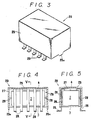
- FIGS 3 though 5 show the second embodiment of the present invention.
- the electromagnetic relay main body packaged in an inner casing 2 consisting of a cover 3 and a base 4 can be used as an ordinary electromagnetic relay for general purpose, but it is further received in a separately manufactured outer casing 25, consisting of an open bottom box, with the base 4 of the inner casing 2 directed inwardly.
- the central parts of the bottom edge of the two longitudinal end walls of the casing 25 are provided with projections 25a for securing the electromagnetic relay 20 by being fitting into corresponding openings provided in the circuit board.
- the inner casing 2 is kept spaced from the inner surface of the outer casing 25 by a plurality of projections 28 projecting from the inner surface of the outer casing 25 and abutting the outer surface of the inner casing 2.
- the space 26 thus defined between the inner casing 2 and the outer casing 25 is filled with a bonding agent 27, and the inner casing 2 and the outer casing 25 are thereby combined into a solid integral body.
- Terminals 29 of the electromagnetic relay main body passed through the base 4 of the inner casing 2 are led out of the upper part of the inner casing 2, and are passed downwardly through the space 26 between the side walls of the inner casing 2 and the outer casing 25 until they are exposed to the exterior of the outer casing 25 at its open bottom end.
- the outer casing 25 is subjected to a high temperature when mounting the electromagnetic relay 20 on the surface of a circuit board, but this heat is first transmitted to the external cover 25 and is dissipated as it is first transmitted through the external cover 25 and the bonding agent 27 whereby the thermal stress acting upon the electromagnetic relay main body is reduced, and an ordinary electromagnetic relay for general purpose may be safely used without producing any thermal deformations. Therefore, the design and manufacturing work of the surface mount type electromagnetic relay is not in any way specialized, and the manufacturing cost can be thereby reduced.
- terminal leads 29 of the electromagnetic relay main body By passing the terminal leads 29 of the electromagnetic relay main body through the interior of the external cover 25 and by thus increasing the lengths of the terminal leads 29, the terminal leads are made so compliant that solder cracks are avoided from occurring when soldering these terminal leads to the circuit patterns of the circuit board.
Landscapes
- Engineering & Computer Science (AREA)
- Microelectronics & Electronic Packaging (AREA)
- Physics & Mathematics (AREA)
- Electromagnetism (AREA)
- Manufacturing & Machinery (AREA)
- Casings For Electric Apparatus (AREA)
- Switch Cases, Indication, And Locking (AREA)
Applications Claiming Priority (4)
| Application Number | Priority Date | Filing Date | Title |
|---|---|---|---|
| JP333088U JPH01107836U (fr) | 1988-01-13 | 1988-01-13 | |
| JP3331/88U | 1988-01-13 | ||
| JP333188U JPH01107837U (fr) | 1988-01-13 | 1988-01-13 | |
| JP3330/88U | 1988-01-13 |
Publications (2)
| Publication Number | Publication Date |
|---|---|
| EP0324439A2 true EP0324439A2 (fr) | 1989-07-19 |
| EP0324439A3 EP0324439A3 (fr) | 1990-01-17 |
Family
ID=26336885
Family Applications (1)
| Application Number | Title | Priority Date | Filing Date |
|---|---|---|---|
| EP89100351A Withdrawn EP0324439A3 (fr) | 1988-01-13 | 1989-01-10 | Boítier pour un relais électromagnétique |
Country Status (1)
| Country | Link |
|---|---|
| EP (1) | EP0324439A3 (fr) |
Cited By (11)
| Publication number | Priority date | Publication date | Assignee | Title |
|---|---|---|---|---|
| EP0432046A1 (fr) * | 1989-12-08 | 1991-06-12 | Compagnie Europeenne De Composants Electroniques Lcc | Boîtier d'encapsulation pour composant électronique |
| EP0945882A3 (fr) * | 1998-03-26 | 2000-10-25 | Siemens Aktiengesellschaft | Relais à faible bruit |
| EP1050895B1 (fr) * | 1999-05-06 | 2005-03-09 | Omron Corporation | Relais électromagnétique |
| WO2008106862A1 (fr) * | 2007-03-03 | 2008-09-12 | Shenzhen Zanty Electronics Co., Ltd | Relais de bornes courbées de type fiche |
| FR2926666A1 (fr) * | 2008-01-23 | 2009-07-24 | Cartier Technologies Soc Par A | Boitier de commande de chauffage electrique a amortissement acoustique |
| CN102122768A (zh) * | 2010-12-21 | 2011-07-13 | 福建捷联电子有限公司 | 一种贴片式的电子接口 |
| WO2012007289A1 (fr) * | 2010-07-12 | 2012-01-19 | Weidmüller Interface GmbH & Co. KG | Pièce moulée destinée à recevoir un module électrique |
| CN102544775A (zh) * | 2012-02-28 | 2012-07-04 | 吴延书 | 一种多芯导线电连接方法及固定装置 |
| EP2290670A4 (fr) * | 2008-05-12 | 2014-01-22 | Nec Tokin Corp | Relais électromagnétique |
| WO2016062495A1 (fr) * | 2014-10-24 | 2016-04-28 | Robert Bosch Gmbh | Protection pour système de batteries pour la séparation électrique et thermique |
| CN110769623A (zh) * | 2019-11-07 | 2020-02-07 | 徐州陀微传感科技有限公司 | 一种电子元器件的安装结构 |
-
1989
- 1989-01-10 EP EP89100351A patent/EP0324439A3/fr not_active Withdrawn
Non-Patent Citations (1)
| Title |
|---|
| 34th Annual National Relay Conference 21 April 1986, Oklahoma,U.S.A. pages 6-1 - 6-9; K.Matsuoka et al: "A Miniature, High Temperature Resisting Relay For Surface Mount" * |
Cited By (15)
| Publication number | Priority date | Publication date | Assignee | Title |
|---|---|---|---|---|
| EP0432046A1 (fr) * | 1989-12-08 | 1991-06-12 | Compagnie Europeenne De Composants Electroniques Lcc | Boîtier d'encapsulation pour composant électronique |
| FR2655808A1 (fr) * | 1989-12-08 | 1991-06-14 | Europ Composants Electron | Boitier d'encapsulation pour composant electronique. |
| US5196651A (en) * | 1989-12-08 | 1993-03-23 | Compagnie Europeenne De Composants Electroniques Lcc | Encapsulation package for electronic component |
| EP0945882A3 (fr) * | 1998-03-26 | 2000-10-25 | Siemens Aktiengesellschaft | Relais à faible bruit |
| EP1050895B1 (fr) * | 1999-05-06 | 2005-03-09 | Omron Corporation | Relais électromagnétique |
| WO2008106862A1 (fr) * | 2007-03-03 | 2008-09-12 | Shenzhen Zanty Electronics Co., Ltd | Relais de bornes courbées de type fiche |
| FR2926666A1 (fr) * | 2008-01-23 | 2009-07-24 | Cartier Technologies Soc Par A | Boitier de commande de chauffage electrique a amortissement acoustique |
| EP2290670A4 (fr) * | 2008-05-12 | 2014-01-22 | Nec Tokin Corp | Relais électromagnétique |
| WO2012007289A1 (fr) * | 2010-07-12 | 2012-01-19 | Weidmüller Interface GmbH & Co. KG | Pièce moulée destinée à recevoir un module électrique |
| CN102122768A (zh) * | 2010-12-21 | 2011-07-13 | 福建捷联电子有限公司 | 一种贴片式的电子接口 |
| CN102544775A (zh) * | 2012-02-28 | 2012-07-04 | 吴延书 | 一种多芯导线电连接方法及固定装置 |
| WO2016062495A1 (fr) * | 2014-10-24 | 2016-04-28 | Robert Bosch Gmbh | Protection pour système de batteries pour la séparation électrique et thermique |
| CN107087436A (zh) * | 2014-10-24 | 2017-08-22 | 罗伯特·博世有限公司 | 用于电池系统的用于电的和热的分开的接触器 |
| CN107087436B (zh) * | 2014-10-24 | 2020-05-05 | 罗伯特·博世有限公司 | 用于电池系统的用于电的和热的分开的接触器 |
| CN110769623A (zh) * | 2019-11-07 | 2020-02-07 | 徐州陀微传感科技有限公司 | 一种电子元器件的安装结构 |
Also Published As
| Publication number | Publication date |
|---|---|
| EP0324439A3 (fr) | 1990-01-17 |
Similar Documents
| Publication | Publication Date | Title |
|---|---|---|
| EP0324439A2 (fr) | Boîtier pour un relais électromagnétique | |
| US7881689B2 (en) | Vehicle radar sensor assembly | |
| JP2907914B2 (ja) | 電気又は電子デバイス又はモジユールの封止方法とパツケージ | |
| US4675629A (en) | Noise filter | |
| US5927259A (en) | Ignition apparatus for internal combustion engine | |
| JP2017092281A (ja) | 電子制御装置 | |
| US4833276A (en) | Shield structure of electronic equipment | |
| US3157828A (en) | Encapsulated printed circuit module with heat transfer means | |
| JP4058172B2 (ja) | 光半導体素子収納用パッケージ | |
| US5606298A (en) | Electrical relay | |
| KR102158267B1 (ko) | 리셉터클 커넥터 | |
| US3187083A (en) | Container for an electrical component | |
| JP2008279847A (ja) | 電子機器 | |
| US20220386454A1 (en) | Electronic control device | |
| US5157587A (en) | Sealing arrangement | |
| JP2842407B2 (ja) | 半導体装置及び半導体装置用パッケージ | |
| JPH0936693A (ja) | 電子部品 | |
| JP3714126B2 (ja) | 電子機器及びその製作方法 | |
| JP5201892B2 (ja) | 光通信用パッケージ | |
| CN110474192B (zh) | 基于过盈配合的信号连接结构及量子芯片封装盒体 | |
| JP2531310Y2 (ja) | 気密端子 | |
| JP2010251614A (ja) | 半導体モジュールおよびその製造方法 | |
| JP2020102565A (ja) | 電子制御装置 | |
| KR100373127B1 (ko) | 컨넥터의 와이어링 보호구조 | |
| JP2552132B2 (ja) | 放電灯安定器 |
Legal Events
| Date | Code | Title | Description |
|---|---|---|---|
| PUAI | Public reference made under article 153(3) epc to a published international application that has entered the european phase |
Free format text: ORIGINAL CODE: 0009012 |
|
| 17P | Request for examination filed |
Effective date: 19890110 |
|
| AK | Designated contracting states |
Kind code of ref document: A2 Designated state(s): AT BE CH DE ES FR GB GR IT LI LU NL SE |
|
| PUAL | Search report despatched |
Free format text: ORIGINAL CODE: 0009013 |
|
| AK | Designated contracting states |
Kind code of ref document: A3 Designated state(s): AT BE CH DE ES FR GB GR IT LI LU NL SE |
|
| RHK1 | Main classification (correction) |
Ipc: H05K 5/00 |
|
| STAA | Information on the status of an ep patent application or granted ep patent |
Free format text: STATUS: THE APPLICATION HAS BEEN WITHDRAWN |
|
| 18W | Application withdrawn |
Withdrawal date: 19901030 |
|
| R18W | Application withdrawn (corrected) |
Effective date: 19901030 |