EP0324462A2 - Klimaanlage - Google Patents
Klimaanlage Download PDFInfo
- Publication number
- EP0324462A2 EP0324462A2 EP89100440A EP89100440A EP0324462A2 EP 0324462 A2 EP0324462 A2 EP 0324462A2 EP 89100440 A EP89100440 A EP 89100440A EP 89100440 A EP89100440 A EP 89100440A EP 0324462 A2 EP0324462 A2 EP 0324462A2
- Authority
- EP
- European Patent Office
- Prior art keywords
- room
- air
- air conditioning
- outlet port
- switch
- Prior art date
- Legal status (The legal status is an assumption and is not a legal conclusion. Google has not performed a legal analysis and makes no representation as to the accuracy of the status listed.)
- Granted
Links
Images





Classifications
-
- F—MECHANICAL ENGINEERING; LIGHTING; HEATING; WEAPONS; BLASTING
- F24—HEATING; RANGES; VENTILATING
- F24F—AIR-CONDITIONING; AIR-HUMIDIFICATION; VENTILATION; USE OF AIR CURRENTS FOR SCREENING
- F24F11/00—Control or safety arrangements
- F24F11/70—Control systems characterised by their outputs; Constructional details thereof
- F24F11/72—Control systems characterised by their outputs; Constructional details thereof for controlling the supply of treated air, e.g. its pressure
- F24F11/79—Control systems characterised by their outputs; Constructional details thereof for controlling the supply of treated air, e.g. its pressure for controlling the direction of the supplied air
-
- F—MECHANICAL ENGINEERING; LIGHTING; HEATING; WEAPONS; BLASTING
- F24—HEATING; RANGES; VENTILATING
- F24F—AIR-CONDITIONING; AIR-HUMIDIFICATION; VENTILATION; USE OF AIR CURRENTS FOR SCREENING
- F24F11/00—Control or safety arrangements
- F24F11/30—Control or safety arrangements for purposes related to the operation of the system, e.g. for safety or monitoring
-
- F—MECHANICAL ENGINEERING; LIGHTING; HEATING; WEAPONS; BLASTING
- F24—HEATING; RANGES; VENTILATING
- F24F—AIR-CONDITIONING; AIR-HUMIDIFICATION; VENTILATION; USE OF AIR CURRENTS FOR SCREENING
- F24F11/00—Control or safety arrangements
- F24F11/62—Control or safety arrangements characterised by the type of control or by internal processing, e.g. using fuzzy logic, adaptive control or estimation of values
- F24F11/63—Electronic processing
- F24F11/65—Electronic processing for selecting an operating mode
-
- F—MECHANICAL ENGINEERING; LIGHTING; HEATING; WEAPONS; BLASTING
- F24—HEATING; RANGES; VENTILATING
- F24F—AIR-CONDITIONING; AIR-HUMIDIFICATION; VENTILATION; USE OF AIR CURRENTS FOR SCREENING
- F24F11/00—Control or safety arrangements
- F24F11/70—Control systems characterised by their outputs; Constructional details thereof
- F24F11/72—Control systems characterised by their outputs; Constructional details thereof for controlling the supply of treated air, e.g. its pressure
- F24F11/74—Control systems characterised by their outputs; Constructional details thereof for controlling the supply of treated air, e.g. its pressure for controlling air flow rate or air velocity
-
- F—MECHANICAL ENGINEERING; LIGHTING; HEATING; WEAPONS; BLASTING
- F24—HEATING; RANGES; VENTILATING
- F24F—AIR-CONDITIONING; AIR-HUMIDIFICATION; VENTILATION; USE OF AIR CURRENTS FOR SCREENING
- F24F11/00—Control or safety arrangements
- F24F11/70—Control systems characterised by their outputs; Constructional details thereof
- F24F11/80—Control systems characterised by their outputs; Constructional details thereof for controlling the temperature of the supplied air
- F24F11/86—Control systems characterised by their outputs; Constructional details thereof for controlling the temperature of the supplied air by controlling compressors within refrigeration or heat pump circuits
-
- F—MECHANICAL ENGINEERING; LIGHTING; HEATING; WEAPONS; BLASTING
- F25—REFRIGERATION OR COOLING; COMBINED HEATING AND REFRIGERATION SYSTEMS; HEAT PUMP SYSTEMS; MANUFACTURE OR STORAGE OF ICE; LIQUEFACTION SOLIDIFICATION OF GASES
- F25B—REFRIGERATION MACHINES, PLANTS OR SYSTEMS; COMBINED HEATING AND REFRIGERATION SYSTEMS; HEAT PUMP SYSTEMS
- F25B2600/00—Control issues
- F25B2600/02—Compressor control
- F25B2600/021—Inverters therefor
-
- Y—GENERAL TAGGING OF NEW TECHNOLOGICAL DEVELOPMENTS; GENERAL TAGGING OF CROSS-SECTIONAL TECHNOLOGIES SPANNING OVER SEVERAL SECTIONS OF THE IPC; TECHNICAL SUBJECTS COVERED BY FORMER USPC CROSS-REFERENCE ART COLLECTIONS [XRACs] AND DIGESTS
- Y02—TECHNOLOGIES OR APPLICATIONS FOR MITIGATION OR ADAPTATION AGAINST CLIMATE CHANGE
- Y02B—CLIMATE CHANGE MITIGATION TECHNOLOGIES RELATED TO BUILDINGS, e.g. HOUSING, HOUSE APPLIANCES OR RELATED END-USER APPLICATIONS
- Y02B30/00—Energy efficient heating, ventilation or air conditioning [HVAC]
- Y02B30/70—Efficient control or regulation technologies, e.g. for control of refrigerant flow, motor or heating
Definitions
- the present invention relates to air blow control in an air conditioning device.
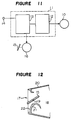
- Figures 11 and 12 shows the essential parts of a conventional inverter drive type of air conditioning device.
- Figure 11 is a block diagram showing the control unit of the conventional air conditioning device.
- Figure 12 is a cross sectional view showing the outlet port of a ceiling mounted or wall mounted type of air conditioning device as for example disclosed in Japanese Examined Patent Publication No. 3349/1982.
- reference numeral 10 designates an electric motor (compressor motor) which is an element constituting an electrically driven compressor.
- the compressor, an indoor heat exchanger, a decompression device and an outdoor heat exchanger are connected in series to form a refrigerant compression cycle.
- Reference numeral 11 designates a control unit which is constituted by compressor frequency generating circuit (inverter) 12 as frequency changing means for the motor 10 and a microcomputer 13 as control means.
- the control unit controls the frequency of three phase a.c. power applied to the motor 10, based on a room temperature detected by a temperature sensor 14.
- Reference numeral 15 designates a blade which is used for changing the flowing direction of air (conditioned air) blown off from an outlet port 17 into the room, and which is arranged in a supply port 18 at a position in the vicinity of its central portion so as to be rotatable about a shaft 19.
- Reference numeral 16 designates a blade driving electric motor as flowing direction changing means, which is used to rotate the blade 15.
- Reference numeral 20 designates the upper end of the outlet port.
- Reference numeral 21 designates a lower guide wall in a curved form, which has the front surface formed with a guiding surface made of heat insulating material 22 having a predetermined thickness.
- the blade 15 is arranged in the supply port 18 in the vicinity of its central portion so as to be rotatable about the shaft 19.
- the conditioned air which flows from the supply port 18 into the outlet port 17 flows along the blade 15, and is blown off from the outlet port 17 in either an upward direction, a lower direction or the horizontal direction depending on the incline of the blade 15.
- the blowing direction of the conditioned air is usually determined taking the temperature distribution in the room and the sense of a user in the room into account.
- the cool air is usually blown off upward in the room, i.e. it is blown off in the horizontal direction in the wall mounted or ceiling mounted type of air conditioning device because such device is mounted at an upper portion in the room, and it is blown off upwardly in an air conditioning device which is put on the floor or mounted on the wall at a lower portion.
- This allows cool air blown off upwardly in the room to cool the space around a user at a lower portion in the room while it is spreading throughout the inside of the room.
- any type of air conditioning devices have been prevented from blowing off cooled air downwardly with intension. Conversely, if warm air is blown off upwardly in the room, the warm air which has risen once does not come down, thereby preventing the space around a user at a lower portion in the room from becoming warm. For the reason, any type of air conditioniong devices have blown off the warm air downwardly in the room so that the warm air blown off downwardly is spreading and rising in the room to warm the entire inside of the room.
- the conventional air conditioning devices have been gradually decreasing the frequency of a.c. power applied to the compressor motor 10 as the actual temperature approaches to a set temperature or when the actual temperature has reached a set temperature once, in both room cooling and room heating operation.
- reference numeral 21 designates an indoor unit housing of the air conditioning device which can carry out room cooling and room heating operation.
- the housing is provided with a upper outlet port 22 and a lower outlet port 23 in the upper and lower portions, and with an intake port 24 in the central portion of the front end.
- Reference numerals 25 and 26 designate cross flow fans which are arranged in the housing so as to correspond to the upper and lower outlet ports 22 and 23.
- Reference numeral 27 designates an indoor heat exchanger which is arranged in the housing so as to correspond to the intake port 24, and which functions as an evaporator on room cooling operation and as a condenser on room heating operation.
- Reference numeral 28 designates an air filter which is provided in the intake port 24.
- Reference numerals 29 and 30 designate fan casings which are placed around the cross for fans 25 and 26.
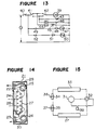
- the refrigerant circuit of this air conditioning device is constituted by a compressor 31, a four port valve 32, an outdoor heat exchanger 33, a capillary tube 34 for room heating operation, a capillary tube 35 for room cooling operation, two check valves 36 and 37, the indoor heat exchanger 27 and a receiver 38, as shown in Figure 15.
- An electric motor 39 for the compressor 31 is connected to power through a main switch 40, a switch 41 having a "cooling" contact and a “heating” contact for selecting either room cooling operation or room heating operation, and a thermostat 42 which is actuated depending on the detection of a room temperature.
- a relay coil 43 for the four port valve 32 has one end connected to a "heating" contact of the switch 41, and the other end connected to power.
- Reference numeral 44 designates a switch (hereinbelow, referred to as a sleep switch) which is actuated when a user goes to bed, and which comprises a pair of two switches, the respective switches having one end connected to the "cooling" contact and the “heating” contact of the switch 41 and the other end connected to power through the relay coils 45 and 46, respectively.
- a fan motor 47 for the upper cross flow fan 25 connected to the main switch 40 through a normally closed relay contact 48 actuated by the relay coil 46, and through a switch 49.
- a lower fan motor 50 for the lower cross flow fan 26 is connected to the main switch 40 through a normally closed relay contacts 51 actuated by the relay coil 45 and through a switch 52.
- the main switch 40 when a normal room cooling or room heating operation is carried out, the main switch 40 is closed, the switch 41 is placed in the position of either the "cooling" contact connection or the “heating” contact connection, and both switches 49 and 52 or either one is closed so as to actuate the compressor 39 and the fan motors 47 and 50, thereby carrying out room cooling or room heating operations.
- the relay coil 45 is energized to open the relay contact 51, thereby stopping the operation of the lower fan motor 50 while continuously driving the upper fan motor 47.
- cool air is blown off only from the upper outlet port 22 of the housing 21 which is mounted on an upper portion of the wall of the room.
- the relay coil 46 is energized to open the relay contact 48, thereby stopping the operation of the upper fan motor 47 while continuously driving the lower fan motor 50.
- warm air is blown off from the lower outlet port of the housing 21 which is amounted at an upper portion of the wall of the room.
- the system can carry out room heating operation appropriate to the time when the user sleeps in bed.
- reference numeral 61 designates an indoor unit housing.
- Reference numeral 62 designates an upper cross flow fan which is arranged at an upper portion in the housing 61.
- Reference numeral 63 designates a lower cross flow fan which is arranged at a lower portion in the housing 61.
- Reference numeral 64 designates an indoor heat exchanger which is arranged near to the front end of the housing 61 and between the upper cross flow fan 62 and the lower cross for fan 63.
- Reference numeral 65 designates an upper outlet port which is formed in an upper front end of the housing 61.
- Reference numeral 66 designate a lower outlet port which is formed in a lower front end of the housing 61.
- speed changing means can drive both upper and lower fans 62 and 63 alternately in a higher speed and in a lower speed to make conditioned air blown off from both outlet ports 65 and 66 flow alternately in the routes indicated by arrows A and C and in the routes indicated by arrows B and D in Figure 17, thereby uniforming air flow distribution in the room to be air conditioned.
- Time signal producing means can control the times of the higher speed and the lower speed of both fans 62 and 64.
- the frequency of a.c. power applied to the compressor motor 10 is decreased.
- the frequency is being gradually decreased as the room temperature approaches to a set temperature.
- the temperature of the conditioned air on room cooling operation is not so low, and the conditioned air is blown off in the horizontal direction or an upward direction so that the conditioned air is prevented from hitting a user directly.
- the upper and lower fans 2 and 3 are driven alternately in the higher speed and in the lower speed in a predetermined pattern by the speed changing means, and the times of the higher speed operation and the lower speed operation are controlled in a predetermined pattern by the time signal generating means.
- This allows the upper air flow and the lower air flow to get in interference with each other and be agitated, thereby obtaining good temperature distribution in the entire inside of the room.
- the air volume control by such system creates the following problem because this system is directed to air condition a signle room.
- control means outputs to flowing direction changing means a signal indicative of the air flow blown off from an outlet port in a downward direction, or when a user actuates a switch is actuated when he desires to allow cool air hit himself directly on room cooling operation, or wherein turning on and off upper fan motor is enabled.
- control means outputs to flowing direction changing means a signal indicative of the air flow blown off from an outlet port in a downward direction, or when a user actuates a switch is actuated when he desires to allow cool air hit himself directly on room cooling operation, or wherein turning on and off upper fan motor is enabled.
- the present invention also provides an air conditioning device wherein conditioned air is blown off from an upper outlet port and a lower outlet port, comprising operation mode selecting means for selecting either a normal mode or a two room air conditioning mode, the normal mode being for air conditioning a room with the indoor unit installed, and the two room air conditioning mode being for air conditioning the room with the indoor unit and its adjoining room; motor speed determining means for determining the revolutions of an upper and lower fans so as to obtain the conditioned air in the amount of volumes suitable to air condition only the room with the indoor unit and to air condition its adjoining room as well, based on mode command signals from the operation mode selecting means.
- the motor speed determining means sets the motor speeds of the upper and lower fans in values optimum to air condition the room with the indoor unit, based on the normal mode command.
- the motor speed determining means sets the revolution of the upper fan motor in such blowing air volume that the conditioned air from the upper outlet port air conditions mainly the room with the indoor unit, and increases the revolution of the lower fan motor in comparison with that of the upper fan motor to obtain such blowing air volume that the conditioned air from the lower outlet port comes into the adjoining room to air condition mainly the adjoining room. This is carried out based on the two room air conditioning mode command.
- the room with the indoor unit and the adjoining room can receive such air flow control by a single air conditioning device. This system can realize comfortable atmosphere desired by user in the two rooms.
- a control unit 11 is constituted by a compressor frequency generating circuit (inverter) 12 as frequency changing means for an electric motor 10 for a compressor, and a microcomputer 13 as control means.
- the microcomputer 13 controls three phase a.c. power to be applied to the motor 10 based on a room temperature detected by a temperature sensor 14.
- the microcomputer 13 also controls an electric motor 16 for driving a blade 15 which is arranged in a supply port.
- the control unit of the first embodiment is provided with a "spot" switch 4 which is depressed when a user desires to allow cool air hit himself directly.
- the “spot” switch 4 is connected to the microcomputer 13 as one of inputs.
- the microcomputer 13 controls the inverter 12 to change the frequency of a.c. power applied to the motor 10 to the maximum frequency.
- the frequency of a.c. power applied to the compressor motor 10 is changed to a value higher than the frequency on normal room cooling operation by the inverter 12.
- the microcomputer 13 also controls the blade 15 through the blade driving motor 16 to place the direction of the blade 15 downwardly, thereby allowing cool air to be blown off downwardly.
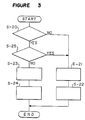
- the normal mode is selected.
- the frequency of a.c. power applied to the compressor motor 10 is controlled by the microcomputer 13 and the inverter 12 so as to make the room temperature approach a set temperature at a step S-21.
- the compressor motor 10 is driven in the maximum frequency which can be attained by the motor 10 because a normal temperature control is carried out.
- the direction of the blade 15 is controlled by the blade driving motor 16 so as to blow off conditioned air in the horizontal direction at a step S-22.
- a spot mode is selected.
- the compressor motor 10 is driven the maximum frequency by the inverter 12 to lower the temperature of the conditioned air at a step S-23.
- the microcomputer 13 controls the blade driving motor 16 to place the blowing direction of the conditioned air downwardly at a step S-24. In this way, cool air hits the user, allowing him to feel cool air sense.
- FIG. 3 is a flow chart wherein such restriction of the spot mode operation is carried out at a step S-25.
- FIG. 4 is a flow chart showing wherein increasing the air volume is carried out at a step S-26 and the air volume is made normal at a step S-27.
- the blowing direction of the conditioned air into the room is placed downwardly, thereby giving cool air sense to the user directly.
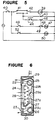
- reference numeral 40 designates a main switch.
- Reference numeral 41 designates a switch having a "cooling" contact and a "heating" contact for selecting either room cooling operation or room heating operation.
- Reference numeral 42 designates a thermostat which is actuated depending on the detection of a room temperature.
- An electric motor 39 for a compressor is connected to power through the switches 40, 41, and the thermostat 42.
- Reference numeral 43 designates a relay coil for a four port valve, which is connected to the "heating" contact of the switch 41.
- Reference numeral 46 designates a relay coil which controls a normally closed contact (further explained below) 48 for an upper fan motor 47.
- the relay coil 46 is connected to the "heating" contact of the switch 41 through a hot air blowing switch 44.
- the upper fan motor 47 is connected to the main switch 40 through the normally closed contact 48 and a switch 49.
- a lower fan motor 50 is connected to the main switch 40 through a switch 52.
- elements indicated by reference numerals 21 through 40 are similar to those of the conventional air conditioner.
- the embodiment as shown in Figure 6 is different from the conventional device in that fan casings 29 and 30 are extended to a partition plate 29a which is arranged at a middle position 27a on the rear surface of indoor heat exchanger so as to form an upper air path 29b and a lower air path 29c separately.
- the main switch 40 is closed, and the switch 41 is placed in the "heating" contact connection to energize the relay coil 43 for the four port valve, thereby placing the refrigerant circuit in the room heating operation cycle.
- the switches 49 and 52 are closed to energize the upper fan motor 47 and the lower fan motor 50, thereby feeding conditioned air from the upper outlet port 22 and the lower outlet port 23.
- the thermostat 42 is connected to the "heating" contact of the switch 41 as the result of the detection of a room temperature in this state, the compressor motor 39 is energized to drive the compressor 31, thereby carrying out room heating operation.
- the hot air blowing switch 44 which the user can operates optionally is provided to be able to control the upper fan motor 47.
- hot air can be hit to the user depending on his desire.
- the first and second embodiments can offer advantage wherein when the user can feel cool air or warm air to his body directly at once, he can only depress the relevant switch to feel cool air or warm air to his body even if the entire inside of the room has not become cool or has not become warm.
- the second embodiment has been explained in reference to the air conditioning device with the upper outlet port and the lower outlet port.
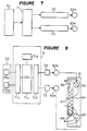
- Figure 7 is a principle block diagram showing the air flow control device according to the third embodiment.
- operation mode selecting means 70 is used to select either a normal mode wherein only a room with the indoor unit installed is air conditioned, or a two room air conditioning mode wherein the room with the indoor unit and a room which adjoins the room with the indoor unit installed through a partition and so on.
- Motor speed determining means 71 functions to determine the revolutions of the upper fan and lower fan based on an operation mode command signal from the oepration mode selecting means 70.
- the motor speed determining means 71 outputs a speed command signal to an upper motor revolution changing device 72 and a lower motor revolution changing device 73.
- the motor revolution changing devices 72 and 73 are connected to an upper fan motor 62a and a lower fan motor 63a, respectively, to drive the motors in either a speed appropriate to air condition a single room or a speed appropriate to air condition two rooms. This arrangement allows a single air conditioning device to air condition not only the room with the device but also the room with the device and its adjoining room comfortably.
- Figure 8 is a block diagram showing the entire structure of the air flow control device of the third embodiment.
- the operation mode selecting means 70 is constituted by a normal mode selecting switch 70a and a two room air conditioning mode selecting switch 70b.
- the motor speed determining means 71 is constituted by a microcomputer which comprises a CPU (central processing unit) 71a for processing the determination of the revolutions of the upper and lower fan motors based on a mode command from the operation mode selecting switches 70a and 70b so as to make the revolutions correspond to each operation mode, a memory 71b for storing the results of the process in the CPU 71a and a program for determining the motor speed and so on, an input circuit 71c for taking a command signal produced by the operation of the mode selecting switches 71a and 70b into the CPU 71a, and an output circuit 71d for output a speed command signal produced as the result of the process in the CPU 71a to the upper fan motor revolution changing device 72 and the lower fan motor revolution changing device 73.
- a CPU central processing unit
- the upper fan motor 62a controlled by the upper fan motor revolution changing device 72 is mechanically connected to an upper fan 62 in the indoor unit 61.
- the lower fan motor 63a controlled by the lower fan motor revolution changing device 73 is mechanically connected to a lower fan 63 in the indoor unit.
- the same reference numerals as those in Figure 16 indicate similar parts.
- a user turns on either the operation mode switch 70a or the operation mode switch 70b to select whether only the room with the indoor unit 61 installed should be air conditioned or the two rooms including the room next to the room with the indoor unit should be air conditioned.
- the operation mode command desired by the user is taken into the CPU 71a through the input the circuit 71c.
- the CPU 71a determines the revolutions of the upper fan 62 and the lower fan 63 depending on the operation mode command.
- the program for processing the determination of the revolutions is stored in the memory 71b, and the CPU 71a decodes the program and executes it, thereby carrying out air flow control. Such air flow control will be described in reference to a flow chart as shown in Figure 9.
- step 81 it is judged at a step 81 whether the operation mode selected by the operation mode selecting switch 70a or 70b is "normal mode” or "two room air conditioning mode". If it is judged that the "normal mode" is selected as the operation mode, the process proceeds to a step 82 where the revolution of the upper fan 2 is set to X1 rpm. At the next step 83, the revolution of lower fan 63 is set to X2 rpm. In this way, the upper fan 62 and the lower fan 63 are simultaneously driven in the revolutions which are appropriate to air conditioned a single room as usual.
- the revolutions of both fans which are appropriate to air condition a single room is preferably be determined so that a rotation ratio which can minimize noise level at a simultaneous operation is realized or low noise operation can be realized with the volume of air flow from both ports restrained. It is because it is enough to make cool air from both fans reach in a short distance.
- step 81 if it is judged at the step 81 that the "two room air conditioning mode" is selected as the operation mode, the process proceeds to a step 84 where the revolution of the upper fan 62 is set to X1 rpm that is the same as the normal mode.
- Such air flow control allows air volume given by the lower fan 63 to increase so that the conditioned air from the lower outlet port 66 can pass through the room 76 with the indoor unit and drastically as indicated an arrow 75 in Fiure 10 to reach its adjoining room 77.
- the conditioned air can pass below the projection 78 because the air feed to the adjoining room 77 is made by the conditioned air from the lower outlet port 66. In this way, the conditioned air blown off from the lower outlet port 66 can come into the adjoining room 77 to air condition mainly the room 77.
- the air volume of the conditioned air from the upper outlet port 65 has the same level as the normal mode as indicated an arrow 79 in Figure 10, which is enough to make the conditioned air reach in a distance corresponding to the single room air condition. If there is the projection 78, the conditioned air from the upper outlet port 65 can not flow into the adjoining room 77 because it is prevented from flowing into it by the projection 78. In this way, the conditioned air from the upper outlet port air conditions mainly the room 76 with the indoor unit.
- the lower fan 63 air conditions the adjoining room 77 while the upper fan 62 air conditions the room 76 with the indoor unit.
- the upper outlet port 65 and the lower outlet port 66 can be assigned to air condition the corresponding rooms, respectively, to realize the two room air conditioning in a comfortable state by a single indoor unit.
- the third embodiment has been explained in reference to a wall mounted type of air conditioning device, the application of the third embodiment is not limited to the wall mounted one. Even if the device is arranged in a wall or a part of the device is mounted on a ceiling, similar advantage can be offered as long as the device has the upper outlet port and the lower outlet port.
- the air conditioning device with the upper outlet port and the lower outlet port it is possible to select either the "normal mode” wherein the room with the indoor unit is air conditioned or the "two room air conditioning mode” wherein a room which adjoins the room with the indoor unit is also air conditioned.
- the revolutions of the upper fan and the lower fan are controlled to produce the air volume of the conditioned air which is appropriate to air condition a single room or two rooms depending on the mode selection.
- the revolution of the lower fan is set to a value higher than that of the upper fan.
Landscapes
- Engineering & Computer Science (AREA)
- Chemical & Material Sciences (AREA)
- Combustion & Propulsion (AREA)
- Mechanical Engineering (AREA)
- General Engineering & Computer Science (AREA)
- Physics & Mathematics (AREA)
- Signal Processing (AREA)
- Fluid Mechanics (AREA)
- Thermal Sciences (AREA)
- Fuzzy Systems (AREA)
- Mathematical Physics (AREA)
- Air Conditioning Control Device (AREA)
Applications Claiming Priority (6)
| Application Number | Priority Date | Filing Date | Title |
|---|---|---|---|
| JP63003384A JPH0765796B2 (ja) | 1988-01-11 | 1988-01-11 | 空気調和機 |
| JP3384/88 | 1988-01-11 | ||
| JP1988003318U JPH01109747U (de) | 1988-01-14 | 1988-01-14 | |
| JP3318/88U | 1988-01-14 | ||
| JP63065182A JPH0754196B2 (ja) | 1988-03-18 | 1988-03-18 | 空気調和機の送風制御装置 |
| JP65182/88 | 1988-03-18 |
Publications (3)
| Publication Number | Publication Date |
|---|---|
| EP0324462A2 true EP0324462A2 (de) | 1989-07-19 |
| EP0324462A3 EP0324462A3 (de) | 1992-03-04 |
| EP0324462B1 EP0324462B1 (de) | 1994-08-31 |
Family
ID=27275755
Family Applications (1)
| Application Number | Title | Priority Date | Filing Date |
|---|---|---|---|
| EP89100440A Expired - Lifetime EP0324462B1 (de) | 1988-01-11 | 1989-01-11 | Klimaanlage |
Country Status (7)
| Country | Link |
|---|---|
| US (1) | US4895002A (de) |
| EP (1) | EP0324462B1 (de) |
| KR (1) | KR920007668B1 (de) |
| CN (1) | CN1034991A (de) |
| AU (1) | AU611248B2 (de) |
| DE (1) | DE68917740T2 (de) |
| HK (1) | HK6095A (de) |
Cited By (6)
| Publication number | Priority date | Publication date | Assignee | Title |
|---|---|---|---|---|
| FR2749069A1 (fr) * | 1996-05-22 | 1997-11-28 | Samsung Electronics Co Ltd | Appareil de commande du flux d'air decharge par un climatiseur et procede correspondant |
| GR970100190A (el) * | 1996-05-22 | 1998-01-30 | Samsung Electronics Co., Ltd | Συσκευη ελεγχου του εξερχομενου αεριου ρευματος απο συσκευη κλιματισμου και μεθοδος δι'αυτον |
| EP0770830A3 (de) * | 1995-10-23 | 1998-03-11 | Sanyo Electric Co. Ltd | Steuerung für Klimaanlage |
| EP1074788A2 (de) | 1999-08-06 | 2001-02-07 | Siteco Beleuchtungstechnik GmbH | Befestigungselement für lichttechnische Komponenten in einer Leuchte |
| EP1925887A3 (de) * | 2006-11-22 | 2013-03-06 | Samsung Electronics Co., Ltd. | Vorrichtung und Verfahren zur Steuerung des Luftstroms einer Klimaanlage im Schlafmodus |
| EP2009361A4 (de) * | 2006-03-31 | 2013-11-20 | Daikin Ind Ltd | Steuervorrichtung und steuerverfahren für eine mehrkammerklimaanlage |
Families Citing this family (7)
| Publication number | Priority date | Publication date | Assignee | Title |
|---|---|---|---|---|
| KR920007668B1 (en) * | 1988-01-11 | 1992-09-14 | Mitsubishi Electric Corp | Air conditioner |
| KR920016791A (ko) * | 1991-02-01 | 1992-09-25 | 이헌조 | 에어콘의 루버위치 및 팬속도 조절회로 |
| US6003593A (en) * | 1995-10-31 | 1999-12-21 | Denso International America, Inc. | Automotive vehicle climate control system |
| FR3068023B1 (fr) * | 2017-06-23 | 2020-05-15 | Rte Reseau De Transport D’Electricite | Dispositif et procede anti-giratoire de levage, suspension et deplacement d'une charge |
| CN112254216B (zh) * | 2020-09-28 | 2022-01-21 | 青岛海尔空调器有限总公司 | 空调室内机、空调、空调遥控器及控制方法 |
| CN114383297B (zh) * | 2021-12-20 | 2023-05-16 | 青岛海尔空调器有限总公司 | 用于控制空调的方法、装置和多联机空调 |
| CN115218414A (zh) * | 2022-06-27 | 2022-10-21 | 青岛海尔空调器有限总公司 | 空调的控制方法、装置、空调及电子设备 |
Family Cites Families (11)
| Publication number | Priority date | Publication date | Assignee | Title |
|---|---|---|---|---|
| JPS5911812B2 (ja) * | 1979-02-06 | 1984-03-17 | 松下電器産業株式会社 | 冷暖房兼用形空気調和機 |
| JPS5930971B2 (ja) * | 1979-03-29 | 1984-07-30 | 松下電器産業株式会社 | 空気調和機の能力制御装置 |
| JPS6138383A (ja) * | 1984-07-31 | 1986-02-24 | 日本酸素株式会社 | 空気液化分離装置における保安液化ガスの寒冷回収方法 |
| JPH0684839B2 (ja) * | 1984-08-29 | 1994-10-26 | 三洋電機株式会社 | 空気調和機 |
| US4729293A (en) * | 1985-03-29 | 1988-03-08 | Kabushiki Kaisha Toshiba | Air direction control apparatus for a louver at an air outlet |
| US4738116A (en) * | 1985-07-08 | 1988-04-19 | Matsushita Electric Industrial Co., Ltd. | Apparatus for deflecting the direction of the wind in an air conditioner |
| JPS6233246A (ja) * | 1985-08-07 | 1987-02-13 | Matsushita Electric Ind Co Ltd | 空気調和機の送風制御装置 |
| AU568801B1 (en) * | 1986-05-21 | 1988-01-07 | Mitsubishi Denki Kabushiki Kaisha | Control system for room air conditioner |
| KR900003870B1 (ko) * | 1986-11-19 | 1990-06-02 | 미츠비시 덴키 가부시키가이샤 | 공기조화기의 송풍 제어장치 |
| CN1010707B (zh) * | 1987-07-02 | 1990-12-05 | 三菱电机株式会社 | 分离型空气调节器 |
| KR920007668B1 (en) * | 1988-01-11 | 1992-09-14 | Mitsubishi Electric Corp | Air conditioner |
-
1988
- 1988-12-21 KR KR8817112A patent/KR920007668B1/ko not_active Expired
-
1989
- 1989-01-09 AU AU28314/89A patent/AU611248B2/en not_active Ceased
- 1989-01-10 CN CN89100162A patent/CN1034991A/zh active Pending
- 1989-01-11 DE DE68917740T patent/DE68917740T2/de not_active Expired - Fee Related
- 1989-01-11 EP EP89100440A patent/EP0324462B1/de not_active Expired - Lifetime
- 1989-01-11 US US07/295,530 patent/US4895002A/en not_active Expired - Fee Related
-
1995
- 1995-01-12 HK HK6095A patent/HK6095A/en not_active IP Right Cessation
Cited By (7)
| Publication number | Priority date | Publication date | Assignee | Title |
|---|---|---|---|---|
| EP0770830A3 (de) * | 1995-10-23 | 1998-03-11 | Sanyo Electric Co. Ltd | Steuerung für Klimaanlage |
| FR2749069A1 (fr) * | 1996-05-22 | 1997-11-28 | Samsung Electronics Co Ltd | Appareil de commande du flux d'air decharge par un climatiseur et procede correspondant |
| GR970100190A (el) * | 1996-05-22 | 1998-01-30 | Samsung Electronics Co., Ltd | Συσκευη ελεγχου του εξερχομενου αεριου ρευματος απο συσκευη κλιματισμου και μεθοδος δι'αυτον |
| ES2147083A1 (es) * | 1996-05-22 | 2000-08-16 | Samsung Electronics Co Ltd | Aparato de control de corriente de aire descargado de un acondicionador de aire y procedimiento aplicable al mismo. |
| EP1074788A2 (de) | 1999-08-06 | 2001-02-07 | Siteco Beleuchtungstechnik GmbH | Befestigungselement für lichttechnische Komponenten in einer Leuchte |
| EP2009361A4 (de) * | 2006-03-31 | 2013-11-20 | Daikin Ind Ltd | Steuervorrichtung und steuerverfahren für eine mehrkammerklimaanlage |
| EP1925887A3 (de) * | 2006-11-22 | 2013-03-06 | Samsung Electronics Co., Ltd. | Vorrichtung und Verfahren zur Steuerung des Luftstroms einer Klimaanlage im Schlafmodus |
Also Published As
| Publication number | Publication date |
|---|---|
| AU2831489A (en) | 1989-07-13 |
| KR890012133A (ko) | 1989-08-24 |
| DE68917740T2 (de) | 1994-12-22 |
| EP0324462B1 (de) | 1994-08-31 |
| AU611248B2 (en) | 1991-06-06 |
| KR920007668B1 (en) | 1992-09-14 |
| EP0324462A3 (de) | 1992-03-04 |
| DE68917740D1 (de) | 1994-10-06 |
| HK6095A (en) | 1995-01-20 |
| US4895002A (en) | 1990-01-23 |
| CN1034991A (zh) | 1989-08-23 |
Similar Documents
| Publication | Publication Date | Title |
|---|---|---|
| US4895002A (en) | Air conditioning device | |
| JPH0635895B2 (ja) | ヒートポンプ式空気調和機の運転制御方法およびヒートポンプ式空気調和機 | |
| GB2252620A (en) | "air-conditioner permitting comfortable sleeping during heating operation" | |
| US4795089A (en) | Room air conditioner | |
| US4909310A (en) | Air flow control device for an air conditioner | |
| JP2007147120A (ja) | 空気調和機 | |
| JP2931484B2 (ja) | 空気調和装置 | |
| EP0466431B2 (de) | Klimagerätregeleinrichtung | |
| JPH0886502A (ja) | 空気調和機 | |
| US5020332A (en) | Air conditioner and a drive apparatus therefor | |
| JPH0566043A (ja) | 空気調和機の風向制御装置 | |
| KR100309822B1 (ko) | 자동차시트공조장치 | |
| JPH08193742A (ja) | 空気調和機 | |
| JP2610271B2 (ja) | 空気調和機 | |
| JPH0526508A (ja) | 空気調和機 | |
| JPS59191842A (ja) | 空気調和機の送風制御装置 | |
| JP2960997B2 (ja) | 空気調和機 | |
| JP3545191B2 (ja) | 床暖房装置及び暖房システム | |
| JPH10197030A (ja) | 空気調和機 | |
| JP3815471B2 (ja) | 空気調和機 | |
| JPH1134633A (ja) | 車両用空調装置 | |
| JPH01181029A (ja) | 空気調和機 | |
| JP2662250B2 (ja) | 車両空調用制御装置 | |
| JPH0861746A (ja) | 空気調和機の制御装置 | |
| JPS625264B2 (de) |
Legal Events
| Date | Code | Title | Description |
|---|---|---|---|
| PUAI | Public reference made under article 153(3) epc to a published international application that has entered the european phase |
Free format text: ORIGINAL CODE: 0009012 |
|
| AK | Designated contracting states |
Kind code of ref document: A2 Designated state(s): BE DE FR GB IT NL SE |
|
| 17P | Request for examination filed |
Effective date: 19901212 |
|
| PUAL | Search report despatched |
Free format text: ORIGINAL CODE: 0009013 |
|
| AK | Designated contracting states |
Kind code of ref document: A3 Designated state(s): BE DE FR GB IT NL SE |
|
| 17Q | First examination report despatched |
Effective date: 19920611 |
|
| GRAA | (expected) grant |
Free format text: ORIGINAL CODE: 0009210 |
|
| AK | Designated contracting states |
Kind code of ref document: B1 Designated state(s): BE DE FR GB IT NL SE |
|
| REF | Corresponds to: |
Ref document number: 68917740 Country of ref document: DE Date of ref document: 19941006 |
|
| ITF | It: translation for a ep patent filed | ||
| ET | Fr: translation filed | ||
| EAL | Se: european patent in force in sweden |
Ref document number: 89100440.0 |
|
| PLBE | No opposition filed within time limit |
Free format text: ORIGINAL CODE: 0009261 |
|
| STAA | Information on the status of an ep patent application or granted ep patent |
Free format text: STATUS: NO OPPOSITION FILED WITHIN TIME LIMIT |
|
| 26N | No opposition filed | ||
| REG | Reference to a national code |
Ref country code: GB Ref legal event code: 746 Effective date: 19951107 |
|
| REG | Reference to a national code |
Ref country code: FR Ref legal event code: D6 |
|
| REG | Reference to a national code |
Ref country code: GB Ref legal event code: 747D |
|
| ITPR | It: changes in ownership of a european patent |
Owner name: REVOCA OFFERTA DI LICENZA AL PUBBLICO; |
|
| REG | Reference to a national code |
Ref country code: FR Ref legal event code: LT |
|
| REG | Reference to a national code |
Ref country code: GB Ref legal event code: 747A Effective date: 19980610 |
|
| REG | Reference to a national code |
Ref country code: GB Ref legal event code: 747C |
|
| PGFP | Annual fee paid to national office [announced via postgrant information from national office to epo] |
Ref country code: SE Payment date: 19990107 Year of fee payment: 11 |
|
| PGFP | Annual fee paid to national office [announced via postgrant information from national office to epo] |
Ref country code: FR Payment date: 19990111 Year of fee payment: 11 |
|
| PGFP | Annual fee paid to national office [announced via postgrant information from national office to epo] |
Ref country code: GB Payment date: 19990114 Year of fee payment: 11 |
|
| PGFP | Annual fee paid to national office [announced via postgrant information from national office to epo] |
Ref country code: DE Payment date: 19990115 Year of fee payment: 11 |
|
| PGFP | Annual fee paid to national office [announced via postgrant information from national office to epo] |
Ref country code: NL Payment date: 19990131 Year of fee payment: 11 |
|
| PGFP | Annual fee paid to national office [announced via postgrant information from national office to epo] |
Ref country code: BE Payment date: 19990324 Year of fee payment: 11 |
|
| PG25 | Lapsed in a contracting state [announced via postgrant information from national office to epo] |
Ref country code: GB Free format text: LAPSE BECAUSE OF NON-PAYMENT OF DUE FEES Effective date: 20000111 |
|
| PG25 | Lapsed in a contracting state [announced via postgrant information from national office to epo] |
Ref country code: SE Free format text: LAPSE BECAUSE OF NON-PAYMENT OF DUE FEES Effective date: 20000112 |
|
| PG25 | Lapsed in a contracting state [announced via postgrant information from national office to epo] |
Ref country code: BE Free format text: LAPSE BECAUSE OF NON-PAYMENT OF DUE FEES Effective date: 20000131 |
|
| BERE | Be: lapsed |
Owner name: MITSUBISHI DENKI K.K. Effective date: 20000131 |
|
| PG25 | Lapsed in a contracting state [announced via postgrant information from national office to epo] |
Ref country code: NL Free format text: LAPSE BECAUSE OF NON-PAYMENT OF DUE FEES Effective date: 20000801 |
|
| GBPC | Gb: european patent ceased through non-payment of renewal fee |
Effective date: 20000111 |
|
| EUG | Se: european patent has lapsed |
Ref document number: 89100440.0 |
|
| PG25 | Lapsed in a contracting state [announced via postgrant information from national office to epo] |
Ref country code: FR Free format text: LAPSE BECAUSE OF NON-PAYMENT OF DUE FEES Effective date: 20000929 |
|
| NLV4 | Nl: lapsed or anulled due to non-payment of the annual fee |
Effective date: 20000801 |
|
| PG25 | Lapsed in a contracting state [announced via postgrant information from national office to epo] |
Ref country code: DE Free format text: LAPSE BECAUSE OF NON-PAYMENT OF DUE FEES Effective date: 20001101 |
|
| REG | Reference to a national code |
Ref country code: FR Ref legal event code: ST |
|
| PG25 | Lapsed in a contracting state [announced via postgrant information from national office to epo] |
Ref country code: IT Free format text: LAPSE BECAUSE OF NON-PAYMENT OF DUE FEES;WARNING: LAPSES OF ITALIAN PATENTS WITH EFFECTIVE DATE BEFORE 2007 MAY HAVE OCCURRED AT ANY TIME BEFORE 2007. THE CORRECT EFFECTIVE DATE MAY BE DIFFERENT FROM THE ONE RECORDED. Effective date: 20050111 |