EP0324732B1 - Gurtstraffer mit gurtbandklemmeinrichtung - Google Patents
Gurtstraffer mit gurtbandklemmeinrichtung Download PDFInfo
- Publication number
- EP0324732B1 EP0324732B1 EP86906791A EP86906791A EP0324732B1 EP 0324732 B1 EP0324732 B1 EP 0324732B1 EP 86906791 A EP86906791 A EP 86906791A EP 86906791 A EP86906791 A EP 86906791A EP 0324732 B1 EP0324732 B1 EP 0324732B1
- Authority
- EP
- European Patent Office
- Prior art keywords
- belt
- clamping
- tightening device
- way
- load
- Prior art date
- Legal status (The legal status is an assumption and is not a legal conclusion. Google has not performed a legal analysis and makes no representation as to the accuracy of the status listed.)
- Expired - Lifetime
Links
- 230000004913 activation Effects 0.000 claims description 3
- 230000000694 effects Effects 0.000 claims description 3
- 238000000034 method Methods 0.000 description 2
- 238000010521 absorption reaction Methods 0.000 description 1
- 230000000903 blocking effect Effects 0.000 description 1
- 230000006835 compression Effects 0.000 description 1
- 238000007906 compression Methods 0.000 description 1
- 230000001360 synchronised effect Effects 0.000 description 1
- 238000011144 upstream manufacturing Methods 0.000 description 1
- 238000004804 winding Methods 0.000 description 1
Images
Classifications
-
- B—PERFORMING OPERATIONS; TRANSPORTING
- B60—VEHICLES IN GENERAL
- B60R—VEHICLES, VEHICLE FITTINGS, OR VEHICLE PARTS, NOT OTHERWISE PROVIDED FOR
- B60R22/00—Safety belts or body harnesses in vehicles
- B60R22/18—Anchoring devices
- B60R22/195—Anchoring devices with means to tension the belt in an emergency, e.g. means of the through-anchor or splitted reel type
- B60R22/1951—Anchoring devices with means to tension the belt in an emergency, e.g. means of the through-anchor or splitted reel type characterised by arrangements in vehicle or relative to seat belt
Definitions
- the invention relates to a belt clamping device for a belt tensioner, in particular for a rotary belt tensioner unit, which works in combination with a retractor or even alone between a retractor and a deflector.
- a retractor in a common housing is a belt tensioner motor that works in rotation. If this pretensioner is activated _ either pyrotechnically using a gas generator or mechanically using a tensioned spring _ the motor housing rotates. A belt loop is formed over a deflection roller. Since the lower retractor locks, the webbing is drawn in from above, i.e. from the occupant over the deflector. Depending on the belt slack and resistance, the motor rotates more or less far, and thus tightens more or less webbing until approximately 20-25 ms moved to T o, the occupant forward and increases the load in the belt webbing strengthens.
- the load is lifted after the belt has been tightened by means of locking teeth on the motor housing and two spring-loaded tooth pawls arranged on the side of the housing legs.
- the support torque is enormously high, because due to the sling load, the load on the deflection pulley is almost twice as high as the accident load that acts on the belt.
- the lever arm from the pivot point of the belt tensioner motor to the deflection roller is very large. Although these very high forces are technically manageable, considerable effort is required.
- the invention has for its object to provide a load in a rotary belt tensioner motor of the type described, which takes place without the participation of the belt tensioner itself and is preferably accomplished in the form of a belt clamp.
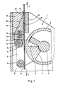
- Fig. 1 shows a sectional view of the essential portion of a belt tensioner 1, which can either be arranged alone between a retractor and a deflector or can be combined with a retractor.
- arrow U the webbing is led to the retractor.
- the Preil O in the belt extension direction points to the deflector located above.
- the rotary belt tensioner 1 with its motor housing 2 is mounted in the housing 17 via the stator 3.
- the rest position shown is fixed.
- the webbing 15 runs into a belt slot 18, which is formed by the clamping ramp 13 and the counter wall 16.
- the bearing block 12 also forms a belt guide with its front edge, so that the belt strap 15 does not come into contact with the teeth 19 of the belt clamping wedge 10 in the rest position.
- the belt clamping wedge 10 is connected via a connection 9 to the guide roller 8 of the belt tensioner 1 through a slot 21 in the bearing block 12.
- the belt clamp wedge 10 lies fully on the bearing block 12 and with its back 20 fully against the sliding surface 22 of the clamping ramp 13.
- Two springs 14 are preloaded between the bearing block 12 and the belt clamping wedge 10.
- the belt tensioner 1 is activated, which is shown here in a pyrotechnic manner.
- An expanding compressed gas flows into the compression space 5, so that the motor housing 2 with the wing 4 begins to rotate counterclockwise.
- the two motor flanges 6 with the deflection materials 7 and the guide roller 8 mounted therein also rotate.
- the deflection materials 7 forms a loop with the belt strap 15. Since the reel located below is locked, only the webbing is pulled in from above, which results in the belt tensioning being achieved.
- the teeth 19 are formed with a sawtooth profile, they have a directionally oriented deflector characteristic, so that the belt strap 15 can be retracted further against the arrow O for the purpose of belt tightening without any significant resistance.
- the motor housing 2 stops. This state occurs approximately 20 ms after T o (beginning of the accident). Now the occupant moves from his seat and falls into the belt. The belt 15 is pulled out in the direction of arrow O. However, since the belt clamping wedge 10 already bears against the belt strap 15 due to the springs 14, the geometric relationships between the clamping ramp 13, the belt clamping wedge 10 and the counter wall 16 immediately result in a belt clamping which takes up the accident load. After only about 2 mm of webbing pull-out, there is already a full belt lock, which has a self-reinforcing character. Neither the belt tensioner 1 nor the retractor arranged underneath is loaded.
- the belt is locked at any point when the belt tensioner 1 has rotated. There are no problems with tooth locking and their requirements for synchronized intervention, full tooth coverage and dynamic resilience. It is only necessary to take up the accident branch at the actual height. There are therefore no increased loads from loop loads or the like inside the device.
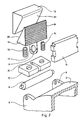
- FIG. 2 shows the parts from FIG. 1 in a perspective exploded view, from which the technical functional relationships can be seen quickly and easily.
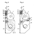
- FIGS. 3 and 4 show the complete assembly of a rotary belt tensioner 1 combined with a retractor. While FIG. 3 shows the normal use situation with the variable belt winding diameters 36, 37, FIG. 4 shows a possible end position after a belt tensioning in the accident.
- the accident branch is guided into the housing 17 by the activated clamping wedge 10, the clamping ramp 13 and the counter wall 16.
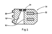
- Fig. 5 shows the possibility, clamping ramp 13 'and counter wall 16' in one part, the terminal housing 30 to combine.
- the load is transferred into the housing 17 via pins 33 and crossbars 32.
- the belt clamping device according to the invention can be used as a load-bearing component for all types of belt tensioners.
Landscapes
- Engineering & Computer Science (AREA)
- Mechanical Engineering (AREA)
- Automotive Seat Belt Assembly (AREA)
Description
- Die Erfindung betrifft eine Gurbandklemmeinrichtung für einen Gurtstraffer, insbesondere für eine rotatorische Gurtstraffereinheit, die in Kombination mit einem Aufroller oder auch allein zwischen einem Aufroller und einem Umlenker arbeitet.
- Gurtstraffer dieser Gattung sind in der EP-A-0 138 507 und in der DE-A-35 37 891 bekannt geworden.
- Oberhalb eines Aufrollers in einem gemeinsamen Gehäuse ist ein rotatorisch arbeitender Gurtstraffermotor angeordnet. Wird dieser Gurtstraffer aktiviert _ entweder pyrotechnisch mittels eines Gasgenerators oder mechanisch über eine gespannte Feder _ so dreht sich das Motorgehäuse. Über eine Umlenkrolle wird eine Gurtschlaufe gebildet. Da der untere Aufroller sperrt, wird das Gurtband von oben, also vom Insassen her über den Umlenker eingezogen. Je nach Gurtlose und Widerstand dreht sich der Motor mehr oder weniger weit und strafft somit mehr oder weniger Gurtband, bis sich ca. 20-25 ms nach To der Insasse nach vorne bewegt und die Belastung im Gurtband starkt ansteigt.
- Die Lastaufnahme nach durchgeführter Gurtstraffung erfolgt über eine Rastverzahnung am Motorgehäuse und zwei seitlich an den Gehäuseschenkeln angeordnete federbelastete Zahnklinken.
- Das Abstützmoment ist dabei enorm hoch, da aufgrund der Schlingenlast die Belastung auf die Umlenkrolle nahezu doppelt so hoch ist, wie die Unfallast, die auf das Gurtband einwirkt. Außerdem ist der Hebelarm vom Drehpunkt des Gurtstraffermotors bis zur Umlenkrolle sehr groß. Wenngleich diese sehr hohen Kräfte technisch beherrschbar sind, so ist dafür doch ein erheblicher Aufwand erforderlich.
- Noch kritischer ist die Situation der Blockiersicherheit, da praktisch ein unsynchronisierter Eingriff der Zahnklinken vorliegt. Der Punkt der Bewegungsumkehr zwischen Straffungsende und Blockiereingriff ist dem Zufall überlassen. Dabei sind, zwar mit geringer Wahrscheinlichkeit, Zahnstellungen möglich, die nur einen halben Zahneingriff ergeben oder Zahnüberspringer oder gar aufgrund von Toleranzen Zahneingriffe rechts und links in nicht korrespondierende Zahnlücken.
- Letzlich ist es auch von Nachteil, den Gurtstraffermotor so stark dimensionieren zu müssen, daß er die gesamte Unfallast mit der bereits geschilderten ungünstigen inneren Kraftentfaltung aufzunehmen hat.
- Der Erfindung liegt die Aufgabe zugrunde, eine Lastaufnahme bei einem Rotations-Gurtstraffermotor der geschilderten Gattung zu schaffen, die ohne Beteiligung des Gurtstraffer selbst erfolgt und vorzugsweise in Form einer Gurtklemmung bewerktstelligt wird.
- Diese Aufgabe wird erfindungsgemäß durch die im Anspruch 1 augegebenen Merkmale gelöst.
- Wird im Falle eines Unfalls der Gurtstraffermotor aktiviert, so bricht bei Bewegungsbeginn die Sollbruchstelle und der Gurtklemmkeil bewegt sich durch die Federkraft auf das Gurtband zu. Aufgrund der Sägezahnform kann jedoch noch ohne nennenswerten Widerstand Gurtband für den Gurtstraffungsvorgang eingezogen werden. Kommt der Motor zum Stillstand, so erfolgt unverzüglich durch den Gurtauszug (der Last) eine Gurtklemmung mit einem Selbstverstärkungseffekt. Eine Deblockierung ist nicht erforderlich, da durch den aktivierten Gurtstraffermotor ohnehin ein Austausch des Gerätes erfolgen muß. Die Lastaufnahme durch die vorgeschaltete Gurtklemmereinheit bietet gegenüber dem Stand der Technik folgende Vorteile.
- 1. Die Dimensionierung des Gurtstraffermotors braucht nur auf die Belastungen ausgelegt zu werden, die sich durch die Gurtstraffung ergibt. Er wird leichter und billiger, auch etwas kleiner.
- 2. Es müssen keinelaußergewöhnlich großen Kräfte innerhalb des Gerätes beherrscht werden.
- 3. Es ergeben sich keine sicherheitsrelevanten Zahneingriffsprobleme (Synchronisation, Zahnüberdeckung usw.)
- In den Zeichnungen ist ein Ausführungsbeispiel der Erfindung dargestellt.
-
- Fig. 1 Gurtstraffermotor mit Gurtbandklemmeinrichtung
- Fig. 2 Explosionsdarstellung der Gurtbandklemmeinrichtung
- Fig. 3/4 Gurtstraffer komplett vor/nach Aktivierung
- Fig. 5 Klemmgehäuse der Gurtbandklemmeinrichtung
- Die Fig. 1 zeigt in Schnittdarstellung den wesentlichen Teilbereich eines Gurtstraffers 1, der entweder für sich allein zwischen einem Aufroller und einem Umlenker angeordnet oder mit einem Aufroller kombiniert sein kann. Gemäß dem Pfeil U wird das Gurtband zum Aufroller geführt. Der Preil O in Gurtauszugsrichtung weist auf den oberhalb angeordneten Umlenker. Über den Stator 3 ist der rotatorische Gurtstraffer 1 mit seinem Motorgehäuse 2 im Gehäuse 17 gelagert. Die dargestellte Ruhestellung ist fixiert. Das Gurtband 15 läuft oben in einen Gurtschlitz 18, der von der Klemmrampe 13 und der Gegenwand 16 gebildet wird. Auch der Lagerbock 12 bildet mit seiner Vorderkante eine Gurtführung, so daß in Ruhestellung das Gurtband 15 nicht mit den Zähnen 19 des Gurtklemmkeiles 10 in Berührung kommt. Durch einen Schlitz 21 im Lagerbock 12 ist der Gurtklemmkeil 10 über eine Verbindung 9 mit der Führungsrolle 8 des Gurtstraffers 1 verbunden. Der Gurtklemmkeil 10 liegt voll auf dem Lagerbock 12 auf und mit seinem Rücken 20 voll gegen die Gleitfläche 22 der Klemmrampe 13 an. Zwei Federn 14 sind zwischen Lagerbock 12 und Gurtklemmkeil 10 vorgespannt.
- Im Falle einer vorbestimmten Verzögerung, die einem Unfall einer bestimmten Schwere entspricht, wird der Gurtstraffer 1 aktiviert, der hier in pyrotechnischer Arbeitsweise dargestellt ist. In den Kompressionsraum 5 fließt ein expandierendes Druckgas, so daß sich das Motorgehäuse 2 mit dem Flügel 4 gegen den Uhrzeigersinn zu drehen beginnt. Somit verdrehen sich auch die beiden Motorflansche 6 mit der darin gelagerten Umlenkroffe 7 und der Führungsrolle 8. Während des Drehvorganges bildet die Umlenkroffe 7 mit dem Gurtband 15 eine Schlaufe. Da der unterhalb angeordnete Aufroller gesperrt ist, wird nur Gurtband von oben hereingezogen, wodurch die Gurtstraffung erzielt wird.
- Beim Drehbeginn des Motorgehäuses 2 bersten die Sollbruchstellen 11 der Verbindung 9, so daß der Gurtklemmkeil 10 von den Federn 14 gegen das Gurtband 15 gedrückt wird.
- Da die Zähne 19 mit einem Sägezahnprofil ausgebildet sind, verfügen sie über eine richtungsorientierte Abweisercharakteristik, so daß das Gurtband 15 zum Zwecke der Gurtstraffung noch weiter entgegen des Pfeiles O ohne nennenswerten Widerstand eingezogen werden kann.
- Ist die im Gurtstraffer 1 enthaltene Energie verbraucht, bleibt das Motorgehäuse 2 stehen. Dieser Zustand stellt sich ungefähr 20 ms nach To (Unfallbeginn) ein. Jetzt bewegt sich der Insasse von seinem Sitz und fällt in den Gurt. Der Gurt 15 wird in Richtung des Pfeiles O herausgezogen. Da aber der Gurtklemmkeil 10 durch die Federn 14 bereits am Gurtband 15 anliegt, ergibt sich aufgrund der geometrischen Verhältnisse zwischen Klemmrampe 13, Gurtklemmkeil 10 und Gegenwand 16 unmittelbar eine Gurtklemmung, die die Unfallast aufnimmt. Nach nur ca. 2 mm Gurtbandauszug liegt bereits eine vollständige Gurtarretierung vor, die einen Selbstverstärkungscharakter aufweist. Weder der Gurtstraffer 1 noch der darunter angeordnete Aufroller wird belastet.
- Die Gurtarretierung erfolgt an jeder beliebigen Stelle, wenn eine Drehung des Gurtstraffers 1 stattgefunden hat. Es existieren keine Probleme mit Zahnverrastungen und deren Anforderungen an synchronisierten Eingriff, voller Zahnüberdeckung und dynamischer Belastungsfähigkeit. Es muß nur die Unfallast in tatsächlich anfallender Höhe aufgenommen werden. Es ergeben sich innerhalb des Gerätes also keine erhöhten Belastungen durch Schlingenlasten o. ä..
- Die Fig. 2 zeigt die Teile aus Fig. 1 in einer perspektivischen Explosionsdarstellung, aus der die technischen Funktionszusammenhänge schnell und einfach zu ersehen sind.
- Die Figuren 3 und 4 zeigen das komplette Aggregat eines mit einem Aufroller kombinierten rotatorischen Gurtstraffers 1. Während die Fig. 3 die normale Gebrauchssituation mit den variablen Gurtwickeldurchmessern 36,37 darstellt, zeigt die Fig. 4 eine mögliche Endstellung nach einer Gurtstraffung im Unfall. Die Unfallast wird vom aktivierten Klemmkeil 10, sowie der Klemmrampe 13 und der Gegenwand 16 in das Gehäuse 17 geleitet.
- Die Fig. 5 zeigt die Mlöglichkeit, Klemmrampe 13′ und Gegenwand 16′ in einem Teil, dem Klemmgehäuse 30 zu vereinigen. Die Lastübertragung in das Gehäuse 17 erfolgt über Zapfen 33 und Querriegel 32.
- Die erfindungsgemäße Gurtklemmeinrichtung kann als lasttragende Komponente für alle Arten von Gurtstraffern eingesetzt werden.
Claims (5)
Applications Claiming Priority (2)
| Application Number | Priority Date | Filing Date | Title |
|---|---|---|---|
| DE3544546 | 1985-12-17 | ||
| DE19853544546 DE3544546A1 (de) | 1985-12-17 | 1985-12-17 | Rotatorischer gurtstraffer fuer sicherheitsgurte |
Publications (2)
| Publication Number | Publication Date |
|---|---|
| EP0324732A1 EP0324732A1 (de) | 1989-07-26 |
| EP0324732B1 true EP0324732B1 (de) | 1991-05-29 |
Family
ID=6288621
Family Applications (1)
| Application Number | Title | Priority Date | Filing Date |
|---|---|---|---|
| EP86906791A Expired - Lifetime EP0324732B1 (de) | 1985-12-17 | 1986-12-04 | Gurtstraffer mit gurtbandklemmeinrichtung |
Country Status (5)
| Country | Link |
|---|---|
| EP (1) | EP0324732B1 (de) |
| JP (1) | JPH01502735A (de) |
| AU (1) | AU6725087A (de) |
| DE (2) | DE3544546A1 (de) |
| WO (1) | WO1987003849A1 (de) |
Families Citing this family (9)
| Publication number | Priority date | Publication date | Assignee | Title |
|---|---|---|---|---|
| US4840325A (en) * | 1986-04-02 | 1989-06-20 | Honda Giken Kogyo Kabushiki Kaisha | Seat belt tightening device |
| DE3629091A1 (de) * | 1986-08-27 | 1988-03-10 | Britax Kolb Gmbh & Co | Umlenkklemmer |
| DE3739356A1 (de) * | 1987-11-20 | 1989-06-01 | Audi Ag | Sicherheitsgurtsystem in kraftfahrzeugen |
| DE3829694A1 (de) * | 1988-09-01 | 1990-03-08 | Autoflug Gmbh | Sicherheitsgurtanordnung mit klemmvorrichtung und darin integriertem gurtstrammer |
| DE4091104T1 (de) * | 1989-06-23 | 1991-06-06 | Takata Corp | Vorspannersystem |
| DE4136623A1 (de) * | 1991-11-07 | 1993-05-13 | Trw Repa Gmbh | Gurtstraffer fuer fahrzeug-sicherheitsgurtsysteme |
| JPH05319212A (ja) * | 1992-05-27 | 1993-12-03 | Takata Kk | ロータリアクチュエータ作動プリテンショナ |
| JP2526348B2 (ja) * | 1992-05-27 | 1996-08-21 | タカタ株式会社 | ロ―タリアクチュエ―タ作動プリテンショナ |
| DE102017105386B4 (de) * | 2017-03-14 | 2021-03-04 | Autoliv Development Ab | Gurtaufrollsystem mit Gurtaufroller und Kraftbegrenzer |
Family Cites Families (6)
| Publication number | Priority date | Publication date | Assignee | Title |
|---|---|---|---|---|
| JPS5631252A (en) * | 1979-08-22 | 1981-03-30 | Hitachi Ltd | Line multiplex system |
| GB2085709A (en) * | 1980-10-21 | 1982-05-06 | Klippan Nv Sa | Tensioning and locking system for safety belts |
| US4492348A (en) * | 1982-01-29 | 1985-01-08 | American Safety Equipment Corporation | Protractive force responsive safety belt locking apparatus |
| DE3343325A1 (de) * | 1983-11-30 | 1985-06-05 | Autoflug Gmbh, 2084 Rellingen | Personen-rueckhaltesystem |
| DE3413488C2 (de) * | 1984-04-10 | 1994-05-11 | Britax Kolb Gmbh & Co | Gurtstrammer |
| DE3432451A1 (de) * | 1984-09-04 | 1986-05-28 | Autoflug GmbH & Co Fahrzeugtechnik, 2084 Rellingen | Sicherheitsgurtanordnung |
-
1985
- 1985-12-17 DE DE19853544546 patent/DE3544546A1/de not_active Withdrawn
-
1986
- 1986-12-04 JP JP62500021A patent/JPH01502735A/ja active Pending
- 1986-12-04 AU AU67250/87A patent/AU6725087A/en not_active Abandoned
- 1986-12-04 DE DE8686906791T patent/DE3679560D1/de not_active Expired - Fee Related
- 1986-12-04 EP EP86906791A patent/EP0324732B1/de not_active Expired - Lifetime
- 1986-12-04 WO PCT/DE1986/000497 patent/WO1987003849A1/de not_active Ceased
Also Published As
| Publication number | Publication date |
|---|---|
| WO1987003849A1 (en) | 1987-07-02 |
| DE3679560D1 (de) | 1991-07-04 |
| JPH01502735A (ja) | 1989-09-21 |
| EP0324732A1 (de) | 1989-07-26 |
| DE3544546A1 (de) | 1987-06-19 |
| AU6725087A (en) | 1987-07-15 |
Similar Documents
| Publication | Publication Date | Title |
|---|---|---|
| EP0300469B1 (de) | Gurtstrammer für Fahrzeugsicherheitsgurte | |
| DE69310959T2 (de) | Kindersitz und Befestigungsstruktur zur Verbindung eines Kindersitzes mit einem Fahrzeugsitz | |
| DE2432956C3 (de) | Gurtaufwickelklemmautomat | |
| EP0148747B1 (de) | Sicherheitsgurtsystem | |
| WO2010106183A1 (de) | Gurtaufrollersystem mit einsteuerglied | |
| DE3407378A1 (de) | Sicherheitsgurtaufroller mit strammvorrichtung | |
| DE3220234A1 (de) | Gurtklemmvorrichtung fuer ein fahrzeuginsassen-rueckhaltegurtsystem | |
| EP0324732B1 (de) | Gurtstraffer mit gurtbandklemmeinrichtung | |
| DE2950443A1 (de) | Gurtband-hemmvorrichtung | |
| DE3008299A1 (de) | Aufrollautomat fuer einen sicherheitsgurt | |
| DE10213065A1 (de) | Sicherheitsgurtvorrichtung | |
| DE3536394C2 (de) | ||
| EP0173903B1 (de) | Sicherheitsgurtanordnung | |
| DE3927868A1 (de) | Fahrzeugsensitives sicherungssystem mit einem beschleunigungssensor | |
| DE3844130A1 (de) | Gurtstrammer fuer fahrzeugsicherheitsgurte | |
| WO1996031642A1 (de) | Gewebtes gurtband für ein fahrzeuginsassenrückhaltesystem | |
| DE3841811C2 (de) | ||
| EP0257604A1 (de) | Umlenkklemmer | |
| EP0943507B1 (de) | Gurtaufroller für ein Fahrzeug-Sicherheitsgurtsystem | |
| DE3328127A1 (de) | Vorrichtung zur sicherheitsgurt-straffung | |
| DE1955498A1 (de) | Verbesserungen an Sicherheitsgurten | |
| DE10357812B4 (de) | Gurtspule für einen Sicherheitsgurtaufroller | |
| DE3925570C2 (de) | ||
| DE3804177A1 (de) | Sicherheitseinrichtung | |
| EP0221542A2 (de) | Gurtaufroller mit Klemmvorrichtung |
Legal Events
| Date | Code | Title | Description |
|---|---|---|---|
| PUAI | Public reference made under article 153(3) epc to a published international application that has entered the european phase |
Free format text: ORIGINAL CODE: 0009012 |
|
| 17P | Request for examination filed |
Effective date: 19880803 |
|
| AK | Designated contracting states |
Kind code of ref document: A1 Designated state(s): AT BE CH DE FR GB IT LI LU NL SE |
|
| RBV | Designated contracting states (corrected) |
Designated state(s): DE FR GB IT SE |
|
| DIN1 | Information on inventor provided before grant (deleted) | ||
| RAP1 | Party data changed (applicant data changed or rights of an application transferred) |
Owner name: GENERAL ENGINEERING (NETHERLANDS) B.V. |
|
| RIN1 | Information on inventor provided before grant (corrected) |
Inventor name: ERNST, HANS-HELLMUT |
|
| 17Q | First examination report despatched |
Effective date: 19900627 |
|
| GRAA | (expected) grant |
Free format text: ORIGINAL CODE: 0009210 |
|
| AK | Designated contracting states |
Kind code of ref document: B1 Designated state(s): DE FR GB IT SE |
|
| PG25 | Lapsed in a contracting state [announced via postgrant information from national office to epo] |
Ref country code: IT Free format text: LAPSE BECAUSE OF FAILURE TO SUBMIT A TRANSLATION OF THE DESCRIPTION OR TO PAY THE FEE WITHIN THE PRESCRIBED TIME-LIMIT;WARNING: LAPSES OF ITALIAN PATENTS WITH EFFECTIVE DATE BEFORE 2007 MAY HAVE OCCURRED AT ANY TIME BEFORE 2007. THE CORRECT EFFECTIVE DATE MAY BE DIFFERENT FROM THE ONE RECORDED. Effective date: 19910529 Ref country code: SE Effective date: 19910529 |
|
| REF | Corresponds to: |
Ref document number: 3679560 Country of ref document: DE Date of ref document: 19910704 |
|
| GBT | Gb: translation of ep patent filed (gb section 77(6)(a)/1977) | ||
| ET | Fr: translation filed | ||
| PLBE | No opposition filed within time limit |
Free format text: ORIGINAL CODE: 0009261 |
|
| STAA | Information on the status of an ep patent application or granted ep patent |
Free format text: STATUS: NO OPPOSITION FILED WITHIN TIME LIMIT |
|
| 26N | No opposition filed | ||
| PGFP | Annual fee paid to national office [announced via postgrant information from national office to epo] |
Ref country code: FR Payment date: 19931125 Year of fee payment: 8 |
|
| PG25 | Lapsed in a contracting state [announced via postgrant information from national office to epo] |
Ref country code: FR Effective date: 19950831 |
|
| REG | Reference to a national code |
Ref country code: FR Ref legal event code: ST |
|
| PGFP | Annual fee paid to national office [announced via postgrant information from national office to epo] |
Ref country code: GB Payment date: 19971125 Year of fee payment: 12 |
|
| PG25 | Lapsed in a contracting state [announced via postgrant information from national office to epo] |
Ref country code: GB Free format text: LAPSE BECAUSE OF NON-PAYMENT OF DUE FEES Effective date: 19981204 |
|
| PGFP | Annual fee paid to national office [announced via postgrant information from national office to epo] |
Ref country code: DE Payment date: 19981214 Year of fee payment: 13 |
|
| GBPC | Gb: european patent ceased through non-payment of renewal fee |
Effective date: 19981204 |
|
| PG25 | Lapsed in a contracting state [announced via postgrant information from national office to epo] |
Ref country code: DE Free format text: LAPSE BECAUSE OF NON-PAYMENT OF DUE FEES Effective date: 20001003 |