EP0324775B1 - Ofen - Google Patents
Ofen Download PDFInfo
- Publication number
- EP0324775B1 EP0324775B1 EP87906592A EP87906592A EP0324775B1 EP 0324775 B1 EP0324775 B1 EP 0324775B1 EP 87906592 A EP87906592 A EP 87906592A EP 87906592 A EP87906592 A EP 87906592A EP 0324775 B1 EP0324775 B1 EP 0324775B1
- Authority
- EP
- European Patent Office
- Prior art keywords
- door
- combustion chamber
- grating
- furnace according
- combustion
- Prior art date
- Legal status (The legal status is an assumption and is not a legal conclusion. Google has not performed a legal analysis and makes no representation as to the accuracy of the status listed.)
- Expired - Lifetime
Links
- 238000002485 combustion reaction Methods 0.000 claims abstract description 51
- 239000002699 waste material Substances 0.000 claims abstract description 44
- 239000000463 material Substances 0.000 claims abstract description 12
- XLYOFNOQVPJJNP-UHFFFAOYSA-N water Substances O XLYOFNOQVPJJNP-UHFFFAOYSA-N 0.000 claims abstract description 12
- 230000005484 gravity Effects 0.000 claims description 2
- 238000007664 blowing Methods 0.000 claims 2
- 230000001737 promoting effect Effects 0.000 claims 1
- 238000010438 heat treatment Methods 0.000 abstract description 2
- 239000000446 fuel Substances 0.000 description 7
- 239000007789 gas Substances 0.000 description 7
- 239000000203 mixture Substances 0.000 description 4
- 238000010276 construction Methods 0.000 description 3
- 230000007246 mechanism Effects 0.000 description 3
- 238000000034 method Methods 0.000 description 3
- 238000004380 ashing Methods 0.000 description 2
- 206010022000 influenza Diseases 0.000 description 2
- 238000011084 recovery Methods 0.000 description 2
- 239000002918 waste heat Substances 0.000 description 2
- 238000003915 air pollution Methods 0.000 description 1
- QVGXLLKOCUKJST-UHFFFAOYSA-N atomic oxygen Chemical compound [O] QVGXLLKOCUKJST-UHFFFAOYSA-N 0.000 description 1
- 230000000694 effects Effects 0.000 description 1
- 239000003344 environmental pollutant Substances 0.000 description 1
- 238000010304 firing Methods 0.000 description 1
- 238000012423 maintenance Methods 0.000 description 1
- 239000002184 metal Substances 0.000 description 1
- 239000007769 metal material Substances 0.000 description 1
- 239000001301 oxygen Substances 0.000 description 1
- 229910052760 oxygen Inorganic materials 0.000 description 1
- 239000002245 particle Substances 0.000 description 1
- 231100000719 pollutant Toxicity 0.000 description 1
- 238000007790 scraping Methods 0.000 description 1
- 239000000779 smoke Substances 0.000 description 1
- 239000007787 solid Substances 0.000 description 1
Images


Classifications
-
- F—MECHANICAL ENGINEERING; LIGHTING; HEATING; WEAPONS; BLASTING
- F23—COMBUSTION APPARATUS; COMBUSTION PROCESSES
- F23G—CREMATION FURNACES; CONSUMING WASTE PRODUCTS BY COMBUSTION
- F23G5/00—Incineration of waste; Incinerator constructions; Details, accessories or control therefor
- F23G5/44—Details; Accessories
- F23G5/442—Waste feed arrangements
- F23G5/448—Waste feed arrangements in which the waste is fed in containers or the like
-
- F—MECHANICAL ENGINEERING; LIGHTING; HEATING; WEAPONS; BLASTING
- F23—COMBUSTION APPARATUS; COMBUSTION PROCESSES
- F23G—CREMATION FURNACES; CONSUMING WASTE PRODUCTS BY COMBUSTION
- F23G5/00—Incineration of waste; Incinerator constructions; Details, accessories or control therefor
- F23G5/08—Incineration of waste; Incinerator constructions; Details, accessories or control therefor having supplementary heating
- F23G5/12—Incineration of waste; Incinerator constructions; Details, accessories or control therefor having supplementary heating using gaseous or liquid fuel
-
- F—MECHANICAL ENGINEERING; LIGHTING; HEATING; WEAPONS; BLASTING
- F23—COMBUSTION APPARATUS; COMBUSTION PROCESSES
- F23G—CREMATION FURNACES; CONSUMING WASTE PRODUCTS BY COMBUSTION
- F23G5/00—Incineration of waste; Incinerator constructions; Details, accessories or control therefor
- F23G5/08—Incineration of waste; Incinerator constructions; Details, accessories or control therefor having supplementary heating
- F23G5/14—Incineration of waste; Incinerator constructions; Details, accessories or control therefor having supplementary heating including secondary combustion
-
- F—MECHANICAL ENGINEERING; LIGHTING; HEATING; WEAPONS; BLASTING
- F23—COMBUSTION APPARATUS; COMBUSTION PROCESSES
- F23G—CREMATION FURNACES; CONSUMING WASTE PRODUCTS BY COMBUSTION
- F23G5/00—Incineration of waste; Incinerator constructions; Details, accessories or control therefor
- F23G5/24—Incineration of waste; Incinerator constructions; Details, accessories or control therefor having a vertical, substantially cylindrical, combustion chamber
- F23G5/245—Incineration of waste; Incinerator constructions; Details, accessories or control therefor having a vertical, substantially cylindrical, combustion chamber with perforated bottom or grate
-
- F—MECHANICAL ENGINEERING; LIGHTING; HEATING; WEAPONS; BLASTING
- F23—COMBUSTION APPARATUS; COMBUSTION PROCESSES
- F23J—REMOVAL OR TREATMENT OF COMBUSTION PRODUCTS OR COMBUSTION RESIDUES; FLUES
- F23J1/00—Removing ash, clinker, or slag from combustion chambers
-
- F—MECHANICAL ENGINEERING; LIGHTING; HEATING; WEAPONS; BLASTING
- F23—COMBUSTION APPARATUS; COMBUSTION PROCESSES
- F23G—CREMATION FURNACES; CONSUMING WASTE PRODUCTS BY COMBUSTION
- F23G2205/00—Waste feed arrangements
- F23G2205/12—Waste feed arrangements using conveyors
- F23G2205/122—Belt conveyor
-
- F—MECHANICAL ENGINEERING; LIGHTING; HEATING; WEAPONS; BLASTING
- F23—COMBUSTION APPARATUS; COMBUSTION PROCESSES
- F23G—CREMATION FURNACES; CONSUMING WASTE PRODUCTS BY COMBUSTION
- F23G2205/00—Waste feed arrangements
- F23G2205/16—Waste feed arrangements using chute
-
- F—MECHANICAL ENGINEERING; LIGHTING; HEATING; WEAPONS; BLASTING
- F23—COMBUSTION APPARATUS; COMBUSTION PROCESSES
- F23G—CREMATION FURNACES; CONSUMING WASTE PRODUCTS BY COMBUSTION
- F23G2206/00—Waste heat recuperation
-
- F—MECHANICAL ENGINEERING; LIGHTING; HEATING; WEAPONS; BLASTING
- F23—COMBUSTION APPARATUS; COMBUSTION PROCESSES
- F23G—CREMATION FURNACES; CONSUMING WASTE PRODUCTS BY COMBUSTION
- F23G2207/00—Control
- F23G2207/10—Arrangement of sensing devices
- F23G2207/101—Arrangement of sensing devices for temperature
-
- F—MECHANICAL ENGINEERING; LIGHTING; HEATING; WEAPONS; BLASTING
- F23—COMBUSTION APPARATUS; COMBUSTION PROCESSES
- F23G—CREMATION FURNACES; CONSUMING WASTE PRODUCTS BY COMBUSTION
- F23G2207/00—Control
- F23G2207/20—Waste supply
-
- F—MECHANICAL ENGINEERING; LIGHTING; HEATING; WEAPONS; BLASTING
- F23—COMBUSTION APPARATUS; COMBUSTION PROCESSES
- F23G—CREMATION FURNACES; CONSUMING WASTE PRODUCTS BY COMBUSTION
- F23G2207/00—Control
- F23G2207/40—Supplementary heat supply
-
- F—MECHANICAL ENGINEERING; LIGHTING; HEATING; WEAPONS; BLASTING
- F23—COMBUSTION APPARATUS; COMBUSTION PROCESSES
- F23H—GRATES; CLEANING OR RAKING GRATES
- F23H2900/00—Special features of combustion grates
- F23H2900/03021—Liquid cooled grates
Definitions
- the invention relates to furnaces for incinerating waste material, which material has unpredictable burning characteristics, and may oxidize endothermically or exothermically.
- FR-A-2057275 describes a furnace for incinerating waste material according to the precharacterising portion of Claim 1 comprising an upright combustion chamber, an inlet for the supply of waste material, an adjustable burner fuelled by gas or oil, and a water cooled jacket.
- an emptying riddle In the lower part, there is an emptying riddle, and a rotary distributor for ash on pallets, which require constant supervision in practice. There is no suggestion of mechanism to permit entry of combustion air through the rotary distributor.
- a furnace for incinerating waste material comprising an upright combustion chamber, an inlet at an upper part of the combustion chamber for supplying the waste material, a burner at a lower part of the combustion chamber fuelled by gas or oil and adjustable in response to the temperature sensed by a temperature sensor to maintain inside the combustion chamber a temperature sufficient for the incineration of the waste material, a water cooled jacket surrounding the combustion chamber CHARACTERISED BY a trap door situated at, a lower part of the combustion chamber arranged to permit air for combustion to pass upwards through a clearance about the door in the closed condition and to open for removing ash from the combustion chamber periodically when required.
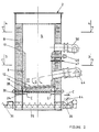
- a three-pass boiler or incinerator with a vertical combustion chamber forming the furnace is generally indicated at 2.
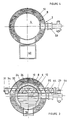
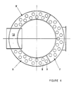
- the boiler contains a chamber 4 which is lined with refractory 6 and has a water jacket 8 with spaces 10 for boiler tubes 9 ( Figures 5,6) and for air passages and has reversal chambers 11 to allow air to move from the chamber 4 down along the outside of the refractory lining past the boiler tubes and hence upwards again in the conventional arrangement of a three-pass boiler as shown by arrows A.
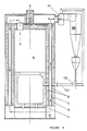
- a sector marked X provides for a downward flow past the boiler tubes 9 and sector Y for an upward flow leading to an induced draft fan 33 shown in Figure 5.
- the boiler may be a wet back boiler with a header on top of the chamber for air emerging from sector Y.
- a grating array 12 which includes a step-wise arrangement of hollow, rectangular section grating tubes 14.
- the tubes 14 are spaced vertically and horizontally.
- Sequentially operable air blast nozzles 120 may be located behind and below (see Figure 7B) so as to leave an air gap to provide the requisite flow.
- the tubes 14 lie parallel to each other but have a longitudinal axis inclined slightly upwards to the horizontal to permit gravity flow.
- An external access door 62 is provided at the lower end. Where appropriate air may be drawn in through this door or other opening at a similar level for aiding combustion.
- a fan 18 blows air underneath the grating as shown by arrow B.
- the air blown below passes between the tubes 14 into the combustion space generally indicated at 17 and helps to ensure that material to be incinerated is burned on the steps.
- air may be drawn in at this location by the induced draft fan 33 ( Figure 5).
- the trap door may be circular and be pivoted aling a substantially diametrical axis, but may in any event be unbalanced to assist the initial opening movement.
- the trap door 24 is received with approximately 20 mm clearance all around in the bottom of the chamber 4 in the closed condition shown in solid lines in Figure 1 and air can pass upwards through the gap into the combustion chamber as shown by arrows C.
- the gap is indicated at 32.
- an inlet for waste materials to be incinerated which inlet includes a chute 40 to the chamber 4.
- a means for supplying waste materials to be incinerated is provided by a conveyor 43 which leads from a storage area 37 to an upwardly inclined slope. Three infrared cells 38 are provided and the conveyor 43 can be operated so that one container, such as a bag or box can pass one at a time through the door 41 which is shown in dotted lines in the open condition of Figure 1.
- the conveyor 43 or elevator may run in reverse a short distance after one container with waste material has been discharged down the chute to avoid any unintentional delivery of the next container.
- a burner 44 is mounted extending substantially radially with respect to the chamber 4 but arranged so as to project fuel admixed with air for combustion in a slightly downward direction (see Figure 2) as shown by arrow D.
- the burner 44 is associated with control means which enables it to supply varying amounts of fuel or to be switched off in a manner explained later on.
- the burner 44 is arranged to swirl the flames around and create the most intensive combustion over the trap door 24 to ensure that any waste material on the trap door is properly incinerated.
- thermo-couple is mounted in a tube 46 to extend through the refractory lining to monitor the combustion temperature.
- a second tube 47 is fitted with a draught controller to maintain a constant negative pressure in the firing chamber created by the main induced draft fan on the outlet side.
- a further fan for supplying secondary air for completing volatile combustion may be arranged in the upper region of the combustion chamber 4 but preferably a secondary burner 50 is used. Both burners 44 and 50 are of a type in which air is drawn in by the burner for admixture with fuel for combustion.
- the induced draft fan 33 sucks into it on the inlet side the exhaust flue. It blows the mixture to a cyclonic separator 100 ( Figure 5) which may have a recirculation passage back to the fan 33.
- the grit particles separated in the separator 100 may be sucked by a Venturi arangement 102 and passed back into the furnace using high pressure outlet air of the fan 33 passed through duct 104 or may be collected and removed by a rotary valve periodically.
- the final mixture from the separator contains no grit and can be passed to atmosphere.
- a system will control operation of the conveyor 43, the burners 44 and 50, the fan 18 and the screw conveyor 35.
- the conveyor 43 will advance bags of waste material or any suitable material for incineration upwardly on the conveyor to the chute 40.
- a desired combustion temperature will have been established in the combustion chamber 4 by using the burner 44 and the air admixed thereto in conjunction with the thermo-couple 46.
- the fan 18 and burner 50 are off and the valve 64 is shut. This only opens when the boiler has to incinerate waste.
- heated water will be produced by the boiler as water is heated by the boiler tubes in the mantle 8 surrounding the chamber 4.
- a bag of waste material 60 will be introduced through the chute 40 and door 41.
- the valve 64 will open after the door has closed.
- the burner 50 will commence operation.
- This bag will fall on top of the grating array 12 and tumble down into the combustion space 17.
- further bags of waste materials will be dropped through the chute so that a row of a few bags will form which will work its way gradually down as the waste material at the bottom of the stack is finally and fully combusted in the combustion zone 17.
- the boiler is now acting in a manner functionally equivalent to an incinerator but the boiler will continue to produce heated water. In the course of this incinerating operation two matters should be noted.
- the air flow from the fan 18 from below the grating 12 will have a fluidising effect on the ash collecting on the grating tubes 14. Also the collection of ash in the gap between the door 24 and the surrounding chamber wall is prevented by the air flow through the gap 32.
- the thermo-couple continues to monitor the combustion temperature inside the chamber 4. Should the waste material contain material of a high calorific value, the control system will turn the burner 44 down to a low fire condition. If the waste material has a sufficiently high calorific value, the burner 44 can in fact be turned off altogether. Should the waste material be such that a considerable heat input is needed to ensure incineration, the burner 44 can be turned to a full fire condition so as to try and maintain the desired combustion temperature. In addition of the combustion temperature exceeds the desired operating limit the control system can interfere with the conveyor 43 so as to prevent the supply of further waste material until the combustion conditions have normalised. This also prevents overfeeding of waste.
- the air passing through the combustion chamber 4 is of fairly constant composition, containing relatively little non-combusted material and being of a fairly high temperature. These conditions are maintained, in the manner explained, whatever the variation in the composition of the waste material.
- the air circulation induced by the fan 33 can be used to prolong combustion with a good excess of oxygen whilst the air gradually travels upwards.
- the flues emerging from the combustion chamber 4 are substantially free of pollutants.
- the incineration operation can be continued or the control settings can be changed back to normal boiler operation using the burner 44 only.
- ash can be removed at regular frequencies.
- the conveyor 36 is switched off to allow all waste materials to be fully combusted.
- the burner goes to a high-fire condition for a preset time and the air flow through the grating is stopped. This condition causes any metal at the bottom of the chamber to become red-hot and soft for facilitating removal.
- the burner 50 is switched OFF to avoid pressurising the boiler system, if appropriate.
- the ash lying on the tubes 14 has been kept fairly loose by the continuous passage of air through the grating 12 during incineration and due to the descent of material to be incinerated.
- the ash is caused to move down onto the grating tube below so that the bulk of the ash accumulates on top of the refractory lining 26 of the trap door 24.
- the burner 44 goes to a low-fire condition to avoid projecting the flame to below the level of the closed door.
- the trap door is pivotted by the actuating lever 30 to the open condition so that the ash drops into the housing 34 for the screw conveyor 35.
- the screw 36 is rotated to remove all the ash and any other debris for collection.
- the screw conveyor permits fine ash as well clumps of waste material which will not burn such as metal material, to be removed without difficulty.
- the trap door 24 is closed and the boiler can once more resume normal operation.
- the boiler 2 can be kept free of ash to substantial extent and the flow of air through the grating 12 and the combustion conditions for the fuel supplied by the burner 44 and the waste material passing through the chute 40 can be kept fairly constant.
- Figure 7B illustrates how where required de-ashing can be promoted by a timed blast of compressed air released from nozzles 120 under solenoid valve control (not shown).
- the different grating levels may be treated in sequence so as to cause the ash to move down step by step.
- Thermocouple controls burner 44 to ensure correct temperature Repeat a to f using timer of control system, unless overridden.
- the cooled grating has a long life and facilitates ash removal.
- the trap door could be slidable as well as pivotable but is preferably as small as possible as is consistent with easy ash removal.
- the inclined tubes 14 permit the grating 12 to be cooled using the same water circuit as is used in the jacket 8.
- the large cross-sectional area ensures flow in all circumstances.
- the conveyor 43 may be replaced by a variety of arrangements for supply waste material containers.
- the waste material could be dropped down by a conveyor from a floor above or in any other convenient manner.
- the screw conveyor for removing ash could also be replaced by a simple chute or by a pneumatic system for removing ash.
- the burner 44 is arranged so that the flame swirls into the bottom of the combustion space 17 ensuring that combustion is complete at the lowermost part of the combustion space 17.
- a simple furnace arrangement can be used to serve a variety of user requirements whilst providing for a lowering of the gas or oil fuel coats.
- the heat recovered from the waste material in this manner exceeds the heat which could be recovered by extracting heat from the exhaust flues of a conventional incinerator.
- Figure 7A shows a modified construction for the lower chamber part.
- a refractory floor is provided which may have apertures to promote ash fluidity or which may be solid.
- the stepped grating may be absent and a grating may be provided level with the door which may or may not be water cooled and/or provided with air apertures for ash fluidity promotion.
- Such a construction would be more appropriate for larger incinerator capacities and where waste is not in a bag of roughly constant size.
- air apertured floor is used as a grating, air drawn in from below the floor aids in keep the apertures clear of ash or debris.
Landscapes
- Engineering & Computer Science (AREA)
- Mechanical Engineering (AREA)
- General Engineering & Computer Science (AREA)
- Environmental & Geological Engineering (AREA)
- Devices That Are Associated With Refrigeration Equipment (AREA)
- Gasification And Melting Of Waste (AREA)
- Processing Of Solid Wastes (AREA)
Claims (12)
- Ofen zum Veraschen von Abfall mit einer aufrechten Verbrennungskammer (4), einem Einlaß an einem oberen Teil der Verbrennungskammer (4) zum Zuführen des Abfalls, einem Brenner (44) an einem unteren Teil der Verbrennungskammer (4), der durch Gas oder Öl versorgt und in Abhängigkeit von der Temperatur einstellbar ist, die durch einen Temperaturfühler (46) gefühlt wird, um innerhalb der Verbrennungskammer (4) eine Temperatur aufrechtzuerhalten, die für das Veraschen des Abfalls ausreichend ist, mit einem wassergekühlten Mantel (8), der die Verbrennungskammer (4) umgibt, gekennzeichnet durch eine Falltür (24), die an einem unteren Teil der Verbrennungskammer (4) angeordnet ist und gestattet, daß Luft für die Verbrennung nach oben durch einen Freiraum (32) um die geschlossene Tür (24) herum hindurchgeht, und die sich periodisch zum Entfernen von Asche aus der Verbrennungskammer (4) öffnen läßt, wenn dies erforderlich ist.
- Ofen nach Anspruch 1, bei dem ein Schraubenförderer (35) unterhalb der Falltür (24) zum Entfernen von Asche angeordnet ist.
- Ofen nach Anspruch 1 oder 2, bei dem ein Rost (12) in der Verbrennungskammer (4) angeordnet ist, der allgemein nach unten geneigt ist, um zu ermöglichen, daß das zu veraschende Material allmählich nach unten wandert, wobei ein Gebläse (18) zum Einblasen von Luft in den Rost (12) vorgesehen ist, um die Asche zu zwingen, nach unten zu wandern, und wobei die Falltür (24) an dem unteren Ende des Rostes (12) angeordnet ist.
- Ofen nach Anspruch 3, bei dem der Rost (12) wassergekühlt ist.
- Ofen nach Anspruch 4, bei dem der Rost (12) nach oben geneigte Durchgänge aufweist, die mit einem Wasserkreislauf verbunden sind, um eine Strömung durch Schwerkraft zu gestatten.
- Ofen nach einem der Ansprüche 3 bis 5, bei dem der Brenner (44) so angeordnet ist, daß er eine Flamme quer über die Falltür (24) richtet, um eine intensive Verbrennung über der Falltür (24) zu schaffen.
- Ofen nach einem der Ansprüche 3 bis 5, bei dem der Rost durch lotrecht versetzte Kesselrohre (14) gebildet ist, die eine Vielzahl von Stufen in einer geneigten Anordnung bilden.
- Ofen nach einem der vorhergehenden Ansprüche, bei dem ein weiterer Brenner (50) an einem oberen Teil der Verbrennungskammer (4) vorgesehen ist, um eine vollständige Verbrennung zu fördern.
- Ofen nach einem der vorhergehenden Ansprüche, der ferner aufweist: Einen Bunker (37) zum Lagern von zu veraschendem Material, einen Förderer (43) zur Aufnahme des Materials von dem Bunker (37), der, wenn erforderlich, antreibbar ist, eine Rutsche (40) zum Fördern des Materials nach unten von dem Ende des Förderers (43) durch den Einlaß in die Verbrennungskammer (4), eine Tür (41) in dem Einlaß und zugehörige Einrichtungen zum Betätigen der Tür (41), wenn erforderlich, sowie Einrichtungen zum Steuern des Förderers (43) und der Türbetätigungseinrichtungen in Abhängigkeit von der Gegenwart von Material in dem Bunker (37) und/oder auf dem Förderer (43) und in Abhängigkeit von dem Ofenzustand.
- Ofen nach Anspruch 9, bei dem der Förderer (43) ein Hebeförderer zum Fördern von Abfallbehältern (60), jeweils einzeln, zu der Rutsche (40) ist.
- Ofen nach Anspruch 10, bei dem der Hebeförderer so gesteuert ist, daß er einen Abfallbehälter (60) in regelmäßigen Zeitabständen übergibt.
- Ofen nach Anspruch 10 oder 11, bei dem der Hebeförderer und die Tür (41) so gesteuert sind, daß die Zuführung von Abfall gestoppt wird, wenn die durch den Fühler (46) gefühlte Ofentemperatur übermäßig hoch oder übermäßig niedrig ist.
Priority Applications (1)
| Application Number | Priority Date | Filing Date | Title |
|---|---|---|---|
| AT87906592T ATE93039T1 (de) | 1986-10-11 | 1987-10-08 | Ofen. |
Applications Claiming Priority (4)
| Application Number | Priority Date | Filing Date | Title |
|---|---|---|---|
| GB8624421 | 1986-10-11 | ||
| GB868624421A GB8624421D0 (en) | 1986-10-11 | 1986-10-11 | Furnace |
| GB08716680A GB2196099A (en) | 1986-10-11 | 1987-07-15 | Furnace |
| GB8716680 | 1987-07-15 |
Publications (2)
| Publication Number | Publication Date |
|---|---|
| EP0324775A1 EP0324775A1 (de) | 1989-07-26 |
| EP0324775B1 true EP0324775B1 (de) | 1993-08-11 |
Family
ID=26291410
Family Applications (1)
| Application Number | Title | Priority Date | Filing Date |
|---|---|---|---|
| EP87906592A Expired - Lifetime EP0324775B1 (de) | 1986-10-11 | 1987-10-08 | Ofen |
Country Status (5)
| Country | Link |
|---|---|
| US (1) | US4976209A (de) |
| EP (1) | EP0324775B1 (de) |
| AT (1) | ATE93039T1 (de) |
| DE (1) | DE3787027T2 (de) |
| WO (1) | WO1988002834A1 (de) |
Families Citing this family (9)
| Publication number | Priority date | Publication date | Assignee | Title |
|---|---|---|---|---|
| DE3839503A1 (de) * | 1988-11-23 | 1990-05-31 | Komanditgesellschaft Avg Abfal | Verfahren und vorrichtung zur reduzierung des co-gehaltes in abgasen von verbrennungsanlagen |
| US5548641A (en) * | 1990-05-15 | 1996-08-20 | Siecor Puerto Rico, Inc. | Protected telephone network termination module |
| US5086720A (en) * | 1991-01-25 | 1992-02-11 | Kahlil Gibran | Furnace for controllable combustion of thermite |
| DE4211839C2 (de) * | 1992-04-08 | 1994-05-05 | Hdg Entwicklung Patent | Verfahren und Vorrichtung zur Regelung des Abbrandes fester Brennstoffe in einer Verbrennungsanlage |
| GB9221821D0 (en) * | 1992-10-16 | 1992-12-02 | Erithglen Ltd | Furnaces |
| US5261335A (en) | 1992-12-29 | 1993-11-16 | Blevins Jr Leslie | Firebox furnace with automatic feeding system |
| AT407082B (de) * | 1999-02-23 | 2000-12-27 | List Guenther | Feuerungsvorrichtung für biomasse, insbesondere holzpellets |
| AT501343B1 (de) * | 2005-02-02 | 2007-03-15 | Calimax Entwicklungs & Vertrie | Heizeinrichtung für stückige brennstoffe |
| EP3792553B8 (de) * | 2018-05-07 | 2024-06-05 | Calisalvo Duran, Luis | Katalytischer oxidator |
Family Cites Families (18)
| Publication number | Priority date | Publication date | Assignee | Title |
|---|---|---|---|---|
| US1813156A (en) * | 1927-10-20 | 1931-07-07 | William A Gilchrist | Furnace |
| US2157993A (en) * | 1935-06-14 | 1939-05-09 | Nichols Engineering And Res Co | Incineration |
| US2698587A (en) * | 1950-07-18 | 1955-01-04 | Simplex Incinerator Corp | Garbage incinerator |
| US2911926A (en) * | 1956-10-08 | 1959-11-10 | Louis Economou | Incinerating device and method |
| US3104629A (en) * | 1958-06-20 | 1963-09-24 | Whirlpool Co | Incinerator |
| US3413936A (en) * | 1964-10-14 | 1968-12-03 | Herbert L. Matthews | Construction and operation of safety dumping system in recovery boilers |
| FR1553766A (de) * | 1966-11-23 | 1969-01-17 | ||
| US3526196A (en) * | 1968-11-21 | 1970-09-01 | Seversky Electronatom Corp | Auxiliary burner assembly for incinerator systems |
| FR2057275A5 (de) * | 1969-08-08 | 1971-05-21 | Missenard Andre | |
| US3769921A (en) * | 1971-12-27 | 1973-11-06 | Mullen F Mc | Waste materials processing system |
| GB1468094A (en) * | 1974-06-18 | 1977-03-23 | Barkhuus P | Furnace for incinerating refuse |
| US4235174A (en) * | 1978-11-24 | 1980-11-25 | Weyerhaeuser Company | Heat recovery from wet wood waste |
| GB2092294B (en) * | 1981-01-28 | 1984-02-08 | Smith Alec Wilfred | Solid fuel burning apparatus |
| JPS5837415A (ja) * | 1981-08-28 | 1983-03-04 | 株式会社 タクマ | 低NOx用ごみ焼却炉 |
| US4454828A (en) * | 1983-01-24 | 1984-06-19 | Zempel Allen M | System for burning bio-mass pellets |
| US4502397A (en) * | 1983-08-15 | 1985-03-05 | Hochmuth Frank W | Pre-drying fuel in steam generator with integral down-draft dryer |
| DE3345087A1 (de) * | 1983-12-13 | 1985-06-13 | Rohleder Kessel- und Apparatebau GmbH, 7000 Stuttgart | Heizkessel |
| SE467433B (sv) * | 1990-11-13 | 1992-07-13 | Asea Brown Boveri | Anordning foer aastadkommande av en, foeretraedesvis elektrisk, foerbindelse mellan en central roterbar del och en omgivande fast del |
-
1987
- 1987-10-08 EP EP87906592A patent/EP0324775B1/de not_active Expired - Lifetime
- 1987-10-08 US US07/340,677 patent/US4976209A/en not_active Expired - Fee Related
- 1987-10-08 AT AT87906592T patent/ATE93039T1/de not_active IP Right Cessation
- 1987-10-08 DE DE87906592T patent/DE3787027T2/de not_active Expired - Fee Related
- 1987-10-08 WO PCT/GB1987/000712 patent/WO1988002834A1/en not_active Ceased
Also Published As
| Publication number | Publication date |
|---|---|
| DE3787027T2 (de) | 1994-03-10 |
| DE3787027D1 (de) | 1993-09-16 |
| EP0324775A1 (de) | 1989-07-26 |
| US4976209A (en) | 1990-12-11 |
| ATE93039T1 (de) | 1993-08-15 |
| WO1988002834A1 (en) | 1988-04-21 |
Similar Documents
| Publication | Publication Date | Title |
|---|---|---|
| EP0235369B1 (de) | Rauchverbrennungsanlage | |
| US4516510A (en) | Incinerator with two reburn stages and, optionally, heat recovery | |
| US4280417A (en) | Incineration plant | |
| US4856438A (en) | Furnace | |
| US5161471A (en) | Apparatus for reburning ash material of a previously burned primary fuel | |
| EP0324775B1 (de) | Ofen | |
| CA1288001C (en) | Furnace | |
| US3645218A (en) | Solid waste incinerator | |
| CS198243B2 (en) | Method of and apparatus for combusting wet waste fuel,especially of vegetal origin | |
| GB2196099A (en) | Furnace | |
| JP2860875B2 (ja) | 二段炉床動床式焼却炉 | |
| JP3909113B2 (ja) | 廃棄物焼却炉 | |
| JP2779145B2 (ja) | 無煙無臭焼却炉 | |
| KR101892907B1 (ko) | 분리형 소각로 자동 처리 설비 | |
| GB2064735A (en) | Incineration process and plant | |
| JPH0125964B2 (de) | ||
| JPS6138371B2 (de) | ||
| NO155462B (no) | Ildsted og fremgangsmaate for fjernelse av aske og slagg fra samme. | |
| NZ213733A (en) | Incinerator system with reburn stage and heat recovery | |
| JPH06109220A (ja) | 廃棄物焼却炉 | |
| CS212421B1 (cs) | Spalovací pec |
Legal Events
| Date | Code | Title | Description |
|---|---|---|---|
| PUAI | Public reference made under article 153(3) epc to a published international application that has entered the european phase |
Free format text: ORIGINAL CODE: 0009012 |
|
| 17P | Request for examination filed |
Effective date: 19890401 |
|
| AK | Designated contracting states |
Kind code of ref document: A1 Designated state(s): AT BE CH DE FR GB IT LI LU NL SE |
|
| 17Q | First examination report despatched |
Effective date: 19891005 |
|
| GRAA | (expected) grant |
Free format text: ORIGINAL CODE: 0009210 |
|
| AK | Designated contracting states |
Kind code of ref document: B1 Designated state(s): AT BE CH DE FR GB IT LI LU NL SE |
|
| PG25 | Lapsed in a contracting state [announced via postgrant information from national office to epo] |
Ref country code: SE Effective date: 19930811 Ref country code: NL Effective date: 19930811 Ref country code: LI Effective date: 19930811 Ref country code: CH Effective date: 19930811 Ref country code: AT Effective date: 19930811 |
|
| REF | Corresponds to: |
Ref document number: 93039 Country of ref document: AT Date of ref document: 19930815 Kind code of ref document: T |
|
| ITF | It: translation for a ep patent filed | ||
| REF | Corresponds to: |
Ref document number: 3787027 Country of ref document: DE Date of ref document: 19930916 |
|
| ET | Fr: translation filed | ||
| PGFP | Annual fee paid to national office [announced via postgrant information from national office to epo] |
Ref country code: FR Payment date: 19931015 Year of fee payment: 7 |
|
| PGFP | Annual fee paid to national office [announced via postgrant information from national office to epo] |
Ref country code: GB Payment date: 19931018 Year of fee payment: 7 |
|
| PGFP | Annual fee paid to national office [announced via postgrant information from national office to epo] |
Ref country code: DE Payment date: 19931019 Year of fee payment: 7 |
|
| PGFP | Annual fee paid to national office [announced via postgrant information from national office to epo] |
Ref country code: BE Payment date: 19931026 Year of fee payment: 7 |
|
| PG25 | Lapsed in a contracting state [announced via postgrant information from national office to epo] |
Ref country code: LU Free format text: LAPSE BECAUSE OF NON-PAYMENT OF DUE FEES Effective date: 19931031 |
|
| REG | Reference to a national code |
Ref country code: CH Ref legal event code: PL |
|
| NLV1 | Nl: lapsed or annulled due to failure to fulfill the requirements of art. 29p and 29m of the patents act | ||
| PLBE | No opposition filed within time limit |
Free format text: ORIGINAL CODE: 0009261 |
|
| STAA | Information on the status of an ep patent application or granted ep patent |
Free format text: STATUS: NO OPPOSITION FILED WITHIN TIME LIMIT |
|
| 26N | No opposition filed | ||
| PG25 | Lapsed in a contracting state [announced via postgrant information from national office to epo] |
Ref country code: GB Effective date: 19941008 |
|
| PG25 | Lapsed in a contracting state [announced via postgrant information from national office to epo] |
Ref country code: BE Effective date: 19941031 |
|
| BERE | Be: lapsed |
Owner name: ERITHGLEN LTD Effective date: 19941031 |
|
| GBPC | Gb: european patent ceased through non-payment of renewal fee |
Effective date: 19941008 |
|
| PG25 | Lapsed in a contracting state [announced via postgrant information from national office to epo] |
Ref country code: FR Effective date: 19950630 |
|
| PG25 | Lapsed in a contracting state [announced via postgrant information from national office to epo] |
Ref country code: DE Effective date: 19950701 |
|
| REG | Reference to a national code |
Ref country code: FR Ref legal event code: ST |
|
| APAH | Appeal reference modified |
Free format text: ORIGINAL CODE: EPIDOSCREFNO |
|
| PG25 | Lapsed in a contracting state [announced via postgrant information from national office to epo] |
Ref country code: IT Free format text: LAPSE BECAUSE OF NON-PAYMENT OF DUE FEES;WARNING: LAPSES OF ITALIAN PATENTS WITH EFFECTIVE DATE BEFORE 2007 MAY HAVE OCCURRED AT ANY TIME BEFORE 2007. THE CORRECT EFFECTIVE DATE MAY BE DIFFERENT FROM THE ONE RECORDED. Effective date: 20051008 |