EP0324959A2 - Verfahren und Vorrichtung zum Korrigieren von Reifenverformungen beim Profilschneiden - Google Patents
Verfahren und Vorrichtung zum Korrigieren von Reifenverformungen beim Profilschneiden Download PDFInfo
- Publication number
- EP0324959A2 EP0324959A2 EP88121255A EP88121255A EP0324959A2 EP 0324959 A2 EP0324959 A2 EP 0324959A2 EP 88121255 A EP88121255 A EP 88121255A EP 88121255 A EP88121255 A EP 88121255A EP 0324959 A2 EP0324959 A2 EP 0324959A2
- Authority
- EP
- European Patent Office
- Prior art keywords
- tyre
- shaft
- radially
- laterally
- cutter
- Prior art date
- Legal status (The legal status is an assumption and is not a legal conclusion. Google has not performed a legal analysis and makes no representation as to the accuracy of the status listed.)
- Granted
Links
Images









Classifications
-
- B—PERFORMING OPERATIONS; TRANSPORTING
- B29—WORKING OF PLASTICS; WORKING OF SUBSTANCES IN A PLASTIC STATE IN GENERAL
- B29D—PRODUCING PARTICULAR ARTICLES FROM PLASTICS OR FROM SUBSTANCES IN A PLASTIC STATE
- B29D30/00—Producing pneumatic or solid tyres or parts thereof
- B29D30/06—Pneumatic tyres or parts thereof (e.g. produced by casting, moulding, compression moulding, injection moulding, centrifugal casting)
- B29D30/52—Unvulcanised treads, e.g. on used tyres; Retreading
- B29D30/68—Cutting profiles into the treads of tyres
Definitions
- the present invention relates to a method and an apparatus for correcting or compensating a cutter position for a radial deflection, in which a tyre surface subjected to cutting deviates in the radial direction, and/or a lateral deflection, in which a tyre surface subjected to cutting deviates in the lateral direction, in a tyre grooving operation.
- An apparatus for grooving in a tread surface of a new tyre or a re-treaded tyre has, in general, a tyre supporting shaft, which supports a tyre in a vertical posture, and a cutter unit, of which at least the lateral movement in the direction parallel with the tyre supporting shaft and the radial movement in the direction perpendicular to the tyre supporting shaft are allowed.
- a tyre itself, in general, does not have an accurate roundness, a tyre tread surface is sometimes inclined to a certain degree and the tyre is sometimes supported in a deviated condition and therefore, a radial distance from the center of the tyre supporting shaft to the tread surface is not constant. Accordingly, radial deflection of the tread surface in the radial direction is caused.
- a tyre grooving wherein the cutter movement is controlled in accordance with a prespecified tread pattern shape by a set-up program with a tyre being rotated, cannot provide constant groove depths for each tyre having same size, and same specification.
- a tyre grooving wherein the cutter movement is controlled in accordance with a prespecified tread pattern shape by a set-up program with a tyre being rotated, cannot make a groove position keep a constant relationship to the tyre tread center for each tyre having same size and same specification.
- a deviation of the tyre tread center in one tyre sometimes results.
- the groove depth cannot be kept constant along the entire circumferential length of the groove which is formed on the entire periphery in the circumferential direction of the tyre because the cutter position in the direction of the cutting depth is kept constant only at the beginning of the cutting operation.
- an image detector is used and the cutter position in the cutting operation is determined by calculation based on the area of the tyre exposed to the view of the detector in order to allow the constant amount of rubber to be cut off.
- the determination of the cutter position by calculation based on the area is very difficult particularly when the cutter acrosses another groove which has been formed already or when the radial fluctuation on the right side of the tyre equator is different from that on the left side, even if the constant amount of rubber to be cut off is purposed. Since the cutter position is not movable in accordance with the radial deflection of the tyre, the groove depth and the groove width cannot be kept at respective desired constant values by following the radial deflection of the tyre.
- the groove position relative to the tread center cannot be kept at a desired constant value by following the lateral deflection of the tyre.
- An object of the present invention is to provide a method and an apparatus for grooving which provide a groove having desired constant depth and width and being formed at a desired constant position even in case that a tyre has a radial deflection and/or a lateral deflection.
- the present invention relates to a method and an apparatus for compensating a radial deflection and a lateral deflection of a tyre in tyre grooving wherein a cutter movement is controlled by a plurality of operating shafts and desired pattern grooves are formed in a tyre surface, wherein the radial deflection in a direction along the diameter of the tyre, which is supported by a tyre supporting shaft, and the lateral deflection in a direction along the width of the tyre are detected before or during tyre grooving, and a radially driving means, which moves a cutter in a direction along diameter of the tyre, and a laterally driving means, which moves the cutter in a direction along width of the tyre, are actuated in accordance with a reference program, and concurrently movements of the radially driving means and the laterally driving means for the cutter are adjusted in accordance with a correction program based on the detected deflection values
- the apparatus of the present invention has detectors for detecting a radial deflection in a direction along diameter of the tyre and a lateral deflection in a direction along width of the tyre; a radially driving shaft which is rotated to move a cutter in a direction along diameter of the tyre under a control of a reference program (or a main program) and a laterally driving shaft which is rotated to move the cutter in a direction along width of the tyre under control of the reference program; and a radially correction shaft and a laterally correction shaft, which are disposed in parallel with the radially driving shaft and the laterally driving shaft respectively, and which are rotated to move the cutter in accordance with a correction program based on the deflection values detected by the detector.
- the radially driving shaft and the laterally driving shaft move the cutter in the direction of tyre diameter and in the direction of tyre width respectively in accordance with the reference program which specifies the cutter position relative to the standard tread surface of the tyre
- the radially correction shaft and the laterally correction shaft move the cutter in accordance with the correction program which corrects the cutter position based on the deflection values detected by the detectors which detect the radial deflection and the lateral deflection of the tyre before or during tyre grooving.
- the correction movements of the radially correction shaft and the laterally correction shaft are mechanically superposed respectively on (or incorporated into) the reference movements of the radially driving shaft and the laterally driving shaft so as to correct the cutter position by compensating the radial deflection and the lateral deflection of the tyre.
- the present invention relates to a method and an apparatus for compensating a radial deflection of a tyre in tyre grooving wherein a cutter movement is controlled by plurality of operating shafts and desired pattern grooves are formed in a tyre surface, wherein the radial deflection in a direction along diameter of the tyre, which is supported by a tyre supporting shaft, is detected before or during tyre grooving, and a radially driving means, which moves a cutter in a direction along diameter of the tyre, is actuated in accordance with a reference program, and concurrently a movement of the radially driving means is adjusted in accordance with a correction program for the cutter based on the detected deflection value in order to follow the radial deflection of the tyre.
- the apparatus of the present invention has a detector for detecting a radial deflection in a direction along diameter of the tyre; a radially driving shaft which is rotated to move a cutter in a direction along diameter of the tyre under a control of a reference program; and a radially correction shaft, which is disposed in parallel with the radially driving shaft, and which is rotated to move the cutter in accordance with a correction program based on the deflection value detected by the detector.
- the radially driving shaft moves the cutter in the direction of tyre diameter in accordance with the reference program which specifies the cutter position relative to the standard tread surface of the tyre
- the radially correction shaft moves the cutter in accordance with the correction program which corrects the cutter position based on the deflection value detected by the detector which detects the radial deflection of the tyre before or during tyre grooving.
- the correction movement of the radially correction shaft is mechanically superposed on (or incorporated into) the reference movement of the radially driving shaft so as to correct the cutter position by compensating the radial deflection of the tyre.
- the present invention relates to a method and an apparatus for compensating a lateral deflection of a tyre in tyre grooving wherein a cutter movement is controlled by a plurality of operating shafts and desired pattern grooves are formed in a tyre surface, wherein the lateral deflection in a direction along width of the tyre, which is supported by a tyre supporting shaft, is detected before or during tyre grooving, and a laterally driving means, which moves a cutter in a direction along width of the tyre, is actuated in accordance with a reference program, and concurrently a movement of the laterally driving means is adjusted in accordance with a correction program for the cutter based on the detected deflection value in order to follow the lateral deflection of the tyre.
- the apparatus of the present invention has a detector for detecting a lateral deflection in a direction along width of the tyre; a laterally driving shaft which is rotated to move the cutter in a direction along width of the tyre under a control of the reference program; and a laterally correction shaft, which is disposed in parallel with a laterally driving shaft, and which is rotated to move the cutter in accordance with a correction program based on the deflection value detected by the detector.
- the laterally driving shaft moves the cutter in the direction of tyre width in accordance with the reference program which specifies the cutter position relative to the standard tread surface of the tyre
- the laterally correction shaft moves the cutter in accordance with the correction program which corrects the cutter position based on the deflection value detected by the detector which detects the lateral deflection of the tyre before or during tyre grooving.
- the correction movement of the laterally correction shaft is mechanically superposed on (or incorporated into) the reference movement of the laterally driving shaft so as to correct the cutter position by compensating the lateral deflection of the tyre.
- Fig. 1 and Fig. 2 show the first embodiment of a grooving apparatus to which the apparatus of the present invention is applied.
- the numeral 1 indicates a bed
- the numeral 2 indicates a tyre support provided on the bed 1
- a tyre 3 is mounted to a tyre supporting shaft 21 and is rotated by a motor 22.
- the numeral 4 indicates a base which is received by a rail 41 on the bed 1 and allowed to move being driven by a motor which is not shown in the drawings along a guide bar 42 in the direction of X-axis perpendicularly to the central axis of the tyre support 2.
- the base 4 can be fixed if the distance between the base 4 and the tyre support 2 is set at a prespecified distance.
- the numeral 5 indicates a laterally travelling stage which is placed on the base 4 and is allowed to move along a rail 43 in the direction of Y-axis in parallel with the tyre supporting shaft 21 and the numeral 6 indicates a laterally driving device for the laterally travelling stage 5.
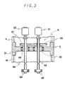
- the laterally driving device 6 employs a construction, as clearly shown in Fig. 3 particularly, wherein a laterally driving shaft 62, which is rotated by a driving motor 61 and comprises a feed screw, and a laterally correction shaft 64, which comprises a spline shaft rotated by a correction motor 63, are mounted in parallel with each other on the base 4 in the direction of Y-aixs parallel to the tyre supporting shaft 21.
- a supporting boss 66 and a female threaded body 65 comprising a ball screw are attached to a frame 51 provided on the under side surface of the laterally travelling stage 5, and the female threaded body 65 is engaged with a threaded part of the laterally driving shaft 62 while the supporting boss 66 is passed through by the laterally correction shaft 64 in such a manner that the supporting boss 66 is rotated together with the laterally correction shaft 64 but the supporting boss 66 is allowed to move freely in the axial direction.
- the numeral 67 indicates a driving gear which is integratedly fixed to the supporting boss 66
- the numeral 68 indicates a driven gear which is loosely passed through by the laterally driving shaft 62 and is fixed to the female threaded body 65, and the driving gear 67 and the driven gear 68 are engaged with each other.
- the numeral 7 indicates a radially travelling stage which is received by the laterally travelling stage 5 and allowed to move along a guide shaft 52 in the direction of Z-axis perpendicularly to the tyre supporting shaft 21 and the numeral 8 indicates a radially driving device for the radially travelling stage 7.
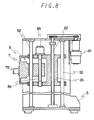
- the radially driving device 8 employs a construction similar to the construction of the aforementioned laterally driving device 6, as shown in Fig.
- a radially driving shaft 82 which is supported in vertical posture by the laterally travelling stage 5 and comprises a feed screw rotatable by a driving motor 81
- a radially correction shaft 84 which is rotated by a correction motor 83 and comprises a spline shaft, are mounted in parallel with each other on the laterally travelling stage 5.
- a female threaded body 85 and a supporting boss 86 are provided rotatably on the radially travelling slage 7, and the female threaded body 85 is engaged with the radially driving shaft 82 while the supporting boss 86 is passed through by the radially correction shaft 84 in such a manner that the supporting boss 86 is rotated together with the radially correction shaft 84 but the supporting boss 86 is allowed to move freely in the axial direction.
- the numeral 87 indicates a driving gear which is rotated together with the radially correction shaft 84 and fixed to the supporting boss 86
- the numeral 88 indicates a driven gear which is loosely passed through by the radially driving shaft 82 and integratedly fixed to the female threaded body 85, and the driving gear 87 and the driven gear 88 are engaged with each other.
- the numeral 71 indicates a rotating arm which is attached to an arm supporting shaft 72 projecting in the direction of X-axis from the radially travelling stage 7 and is rotated around a central axis 73 of the arm supporting shaft 72 in the direction of the arrow A shown in Fig. 2 by a motor which is not shown in the drawing.
- the numeral 9 indicates a cutter supporting unit attached in such a manner that the cutter supporting unit 9 projects perpendicularly toward the central axis 73 from the rotating arm 71.
- the cutter supporting unit 9 employs a construction wherein a cutter supporting frame 92 is attached to a supporting rod 91 supported by the rotating arm 71, a cutter holder 94 is attached to the cutter supporting frame 92 with an insulating member 93 being disposed therebetween, a cutter 10 is removably attached to the cutter holder 94 in such a manner that a cutting point P is located on the extended line from the central axis 73, and the cutter 10 is heated up by an electric power supply unit which is not shown in the drawing.
- the numeral 11 indicates a motor which rotates the cutter supporting unit 9 to change the direction of the cutter 10.
- the numeral 12 indicates an actuator which provide up-down movement of the cutter supporting unit 9 to make the cutting point P of the cutter 10 positioned on the central axis 73.
- the numeral 13 indicates a lateral deflection detector which is faced to the buttress of the tyre side surface keeping an adequate distance m and detects a lateral deflection of the tyre.
- the lateral deflection detector 13 there can be used, for example, a reflex type optical displacement sensor of which the position can be adjusted in accordance with the tyre diameter by means of a supporting unit 131 attached to the tyre support 2. The detected value therefrom is given to a control unit not shown in the drawing as an input so as to drive the correction motor 63 of the laterally driving device 6.
- the numeral 14 indicates a radial deflection detector which detects a radial deflection of the tread surface of the tyre 3.
- the radial deflection detector 14 there can be used, for example, a reflex type optical displacement sensor which is attached to the rotating arm 7 or to the cutter supporting frame 92 in such a manner that light is emitted to the tyre tread surface in the direction toward the tyre center.
- the detected value therefrom is given to a control unit not shown in the drawing as an input so as to drive the correction motor 83 of the radially driving device 8.
- Fig. 5 shows an example of a mounting device for the radial deflection detector, in which a guide rod 142 is supported in parallel with the tyre tread surface by a bracket 141 to be attached to the rotating arm 71, a supporting plate 143 is attached slidably along the guide rod 142, and a reflex type optical displacement sensor 14 is attached to the end of the supporting plate 143.
- the cutter supporting unit is moved upward or downward by means of the radially travelling stage 7 in accordance with the tyre size, the supporting plate 143 is slid along the guide rod 142 so that the light from the sensor 14 is emitted in the direction toward the tyre center.
- Fig. 6 and Fig. 7 show another example of the laterally driving device 6 for driving the laterally travelling stage 5, wherein a laterally driving shaft 62, which is rotated by a driving motor 61 and comprises a feed screw, is mounted on the base 4, and an intermediate supporting stage 602, which is supported by the laterally driving shaft 62 and a guide rod 601, is moved by the rotation of the laterally driving shaft 62 with the assistance of a female threaded body 603.
- a correction motor 63 and a laterally correction shaft 64 comprising a feed screw are mounted on the intermediate supporting stage 602, and a female threaded body 604, which is attached to a laterally travelling stage 5 received by a rail 43, is engaged with the laterally correction shaft 64.
- the numeral 605 indicates a bearing.
- Fig. 8 shows another example of the radially driving device 8, wherein a radially driving shaft 82, which is rotated by a driving motor 81 and comprises a feed screw, is engaged with a female threaded body 85, which is supported by a guide shaft 52, and a radially correction shaft 84, which comprises a feed screw disposed in parallel with the radially driving shaft 82, and a correction motor 83 are attached to the female threaded body 85, further a radially travelling stage 7 is engaged with the radially correction shaft 84.
- the above grooving apparatus explained as the first embodiment employs a construction wherein a cutter is located above a tyre and is moved in up-down direction
- the present invention can be applied to another type of apparatus wherein a cutter is located in front of or behind a tyre and is moved in a horizontal direction perpendicularly to a tyre supporting shaft.
- the correction motor can be a motor having a small capacity and can be operated at a low speed because the correction motor only have to provide a small correction of the cutter position.
- the radial deflection detector and the lateral deflection detector are not limited to the reflect type optical displacement sensors but there can be used a contact type differential transformer or a digital type dial gauge. Further, lateral deflection sensors 13 may be provided on either side of the tyre to correct the cutter position based on the detected values on both sides.
- a position of an origin of each operating shaft is specified based on a command from a computer, which is not shown in the drawings, appropriately for a selected grooving pattern.
- Control values for a tyre without deflections have been given to a reference program of the computer as an input and the direction of the cutter 10 is set by the motor 11 so as to agree with the cutting direction in accordance with the reference program.
- the tyre 3 is rotated in the direction of the arrow (Fig. 1) by the motor 22, and concurrently the driving motor 81 of the radially driving device 8 for the radially travelling stage 7 is operated, then the radially travelling stage 7 is moved downwardly along the direction of Z-axis by the rotational movement of the radially driving shaft 82 with the assistance of the female threaded body 85, so that the cutter 10 which has been heated up by electric power supply cuts in the tyre 3.
- the driving motor 61 of the laterally driving device 6 is moved in accordance with a prespecified groove shape under the control of the reference program, and thus the lateral movement of the cutter 10 is controlled by the movement of the laterally travelling stage 5 in the direction of Y-axis by the rotational movement of the laterally driving shaft 62, so that the prespecified grooving is carried out.
- the device is designed so that the female threaded body 85 moves upwardly on the radially driving shaft 82 when being rotated in such a manner as described above. Accordingly the radially travelling stage 7 is moved upwardly in the Z-direction and therefore the cutter 10 is moved upwardly so that the cutter position is corrected and the depth d is kept constantly.
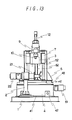
- a tyre has a lateral deflection E2 and the tread center is deviated from a position a1 to a position b1 as shown in Fig. 10, the lateral deflection E2 is detected by the lateral deflection detector 13. Then the correction motor 63 of the laterally driving device 6 is controlled by the correction program based on the detected deflection value, and thus, in case of the example of the laterally driving device shown in Fig. 3, the female threaded body 65 is rotated by the laterally correction shaft 64 with the assistance of the driving gear 67 and the driven gear 68, so that the cutter position is corrected to a position shown by a dotted line in Fig. 10 by the lateral movement in the direction of Y-axis of the laterally travelling stage 5. Accordingly a distance M from the tyre center to the groove position is kept constantly.
- the laterally correction shaft 64 is rotated by the rotation of the correction motor 63, and thus the laterally travelling stage 5 is moved with the assistance of the female threaded body 604.
- the cutting point P of the cutter is constantly controlled in agreement with the tread surface and also the cutter position is adjusted according to the lateral deflection E2 of the tyre, and therefore the position of the groove relative to the tyre center is kept constantly along the entire periphery of the tyre.
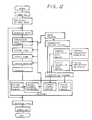
- FIG. 12 there is explained an example of operation using the grooving apparatus of the first embodiment, wherein a tyre is rotated prior to the grooving operation and the deflections of the tyre at any rotational positions are detected and stored in advance, and the stored deflection data is read out in the grooving operation to be used for calculation so that the correction of the cutter position is carried out.
- the radial deflection sensor 14 is arranged so as to be faced to the tyre tread where grooving operation is performed, and the lateral deflection sensor 13 is arranged so as to be faced to the tyre buttress.
- the tyre 3 is rotated at a low speed and the origin mark is brought in agreement with the radial deflection sensor 14 to set an origin for a numerical control. Starting from this condition, the tyre 3 is rotated to make one revolution, and during this rotation the detected values by the radial deflection sensor 14 and the lateral deflection sensor 13 are stored in a memory together with corresponding rotational angular positions.
- the data collected by the radial deflection sensor 14 represents a central position data of the grooves to be formed.
- the tyre supporting shaft 21 is rotated and concurrently the cutter 10 is controlled by a plurality of operating shafts such as a laterally driving shaft, a radially driving shaft, a rotating shaft etc. under the control of the main program of the numerical control device, thereby the movement of a cutter is automatically controlled for tyre grooving, and is moved downwardly to be brought into contact with the prespecified position of the tyre. Meanwhile the cutter has been heated up, and a prespecified grooving operation is carried out according to the rotational angular position with respect to the origin with a prespecified locus being formed.
- a prespecified grooving operation is carried out according to the rotational angular position with respect to the origin with a prespecified locus being formed.
- the stored radial deflection data is read out from the memory according to the rotational angular position of the tyre, and the correction value from the correction program is calculated in accordance with a correction program control command from the main program.
- the radially correction shaft 84 is rotated by the correction motor 83 of the radially driving device 8 based on the radial deflection correction value, and thus the movement caused by the correction program is added to (or substracted from) the movement caused by the main program for the radial movement of the cutter 10.
- the stored lateral deflection data is read out from the memory according to the rotational angular position on the periphery of the buttress, and the correction motor 63 of the laterally driving device 6 is operated based on the lateral deflection correction value calculated by the correction program.
- the laterally correction shaft 64 is rotated and the movement caused by the correction program is added to (or subtracted from) the movement caused by the reference program for the lateral movement of the cutter 10.
- the first embodiment of the apparatus for compensating deflection of the present invention employs a construction wherein the apparatus comprises the laterally driving shaft to move the cutter in parallel with the tyre supporting shaft, the radially driving shaft to move the cutter perpendicularly to the tyre supporting shaft and the detector to detect the lateral deflection and the radial deflection of the tyre, and the laterally driving shaft and the radially driving shaft are controlled by the standard movement (or the reference movement), and concurrently the cutter movement is corrected by superposing the correction movement according to the detected value of the detector on the standard movement. Therefore, the groove depths and the groove positions of tyres can be kept constant even if there are radial deflections and/or lateral deflections in the tyre.
- the reference movement is always controlled based on the prespecified value by the reference program and the correction movement based on the detected deflection value can be superposed on the standard movement by the separate correction program, the structure of the program can be simplified and the apparatus can be made smaller, and the correction is performed surely.
- the groove depth and the groove position with respect to the tyre center can be always kept constant and the uniform grooving can be achieved.
- Fig. 13 is a front view of the apparatus of the second embodiment.
- a side view of the second embodiment is omitted because it is same as the side view of the first embodiment (Fig. 1) excepting that the laterally correction shaft 64 shown in Fig. 1 is not employed in the second embodiment.
- Fig. 13 shows the second embodiment of a grooving apparatus to which the apparatus of the present invention is applied.
- the numeral 1 indicates a bed
- the numeral 2 indicates a tyre support provided on the bed 1
- a tyre 3 is mounted to a tyre supporting shaft 21 and is rotated by a motor 22.
- the numeral 4 indicates a base which is received by a rail 41 on the bed 1 and allowed to move being driven by a motor which is not shown in the drawings along a guide bar 42 in the direction of X-axis perpendicularly to the central axis of the tyre support 2.
- the base 4 can be fixed if the distance between the base 4 and the tyre support 2 is set at a prespecified distance.
- the numeral 5 indicates a laterally travelling stage which is placed on the base 4 and is allowed to move along a rail 43 in the direction of Y-axis in parallel with the tyre supporting shaft 21 and a laterally driving device for the laterally travelling stage 5 is provided thereunder.
- the laterally driving device employs a construction, wherein a laterally driving shaft, which is rotated by a driving motor 61 and comprises a feed screw, and a guide bar are mounted in parallel with each other on the base 4 in the direction of Y-aixs parallel to the tyre supporting shaft 21. And a female threaded body comprising a ball screw is attached to a frame provided on the under side surface of the laterally travelling stage 5, and the female threaded body is engaged with a threaded part of the laterally driving shaft.
- the numeral 7 indicates a radially travelling stage which is received by the laterally travelling stage 5 and allowed to move along a guide shaft 52 in the direction of Z-axis perpendicularly to the tyre supporting shaft 21 and a radially driving device for the radially travelling stage 7 having the same construction as that shown in Fig. 1 and Fig. 4 is provided.
- the numeral 9 indicates a cutter supporting unit having the same construction as that shown in Fig. 1 and the numeral 12 indicates an actuator which provide up-down movement of the cutter supporting unit 9 to make the cutting position P of the cutter 10 be positioned on the central axis 73.
- the same device as that used in the first embodiment can be used.
- the device shown in Fig. 8 can be employed instead of the device shown in Fig. 4 as previously mentioned.
- the correction motor can be a motor having a small capacity and can be operated at a low speed because the correction motor only have to provide a small correction of the cutter position.
- the radial deflection detector and the lateral deflection detector are not limited to the reflect type optical displacement sensors but there can be used a contact type differential transformer or a digital type dial gauge.
- FIG. 14 there is explained hereinafter an operation for correcting a cutter position using the apparatus of the second embodiment, in which a deflection of a tyre is detected and the detected deflection data is collected to be incorporated into calculation.
- a position of an origin of each operating shaft is specified based on a command from a computer, which is not shown in the drawings, appropriately for a selected grooving pattern.
- Control value for a tyre without deflections has been given to a reference program of the computer as an input and the direction of the cutter 10 is set by a motor and the like so as to agree with the cutting direction in accordance with the reference program.
- the tyre 3 is rotated by the motor 22, and concurrently the driving motor of the radially driving device for the radially travelling stage 7 is operated, then the radially travelling stage 7 is moved downwardly along the direction of Z-axis by the rotational movement of the radially driving shaft 82 with the assistance of the female threaded body, so that the cutter 10 which has been heated up by electric power supply cuts in the tyre 3.
- the cutter 10 cuts in the tyre 3 from a standard tread surface F to a prespecified depth d as shown in Fig. 9 under the control of the standard program.
- the driving motor of the laterally driving device is moved in accordance with a prespecified groove shape under the control of the reference program, and thus the lateral movement of the cutter 10 is controlled by the movement of the laterally travelling stage 5 in the direction of Y-axis driven by the rotational movement of the laterally driving shaft, so that the prespecified grooving is carried out.
- the device is designed so that the female threaded body 85 moves upwardly on the radially driving shaft 82 when being rotated in such a manner as described above. Accordingly the radially travelling stage 7 is moved upwardly in the Z-direction and therefore the cutter 10 is moved upwardly so that the cutter position is corrected and the depth d is kept constantly.
- the female threaded body 85 is moved by the radially driving shaft 82 under the control of the reference program, and the rotation of the correction motor 83 rotates the radially correction shaft 84 based on the detected value and thereby the radially travelling stage 7 is moved upwardly.
- the radial deflection of the tyre is detected during the grooving operation and the position of the radially travelling stage is controlled by the radially driving shaft under the control of the reference program and is adjusted in accordance with the correction program.
- the cutting point P of the cutter is controlled in agreement with the tread surface and also the cutter position is adjusted according to the lateral deflection E2 of the tyre during the grooving operation, and therefore the cutter depth is kept constantly along the entire periphery of the tyre.
- FIG. 15 there is explained another example of operation using the grooving apparatus of the second embodiment, wherein a tyre is rotated prior to the grooving operation and the deflections of the tyre at any rotational positions are detected and stored in advance, and the stored deflection data is read out in the grooving operation to be used for calculation so that the correction of the cutter position is carried out.
- the radial deflection sensor 14 is arranged so as to be faced to the tyre tread where grooving operation is performed.
- the tyre 3 is rotated at a low speed and the origin mark is brought in agreement with the radial deflection sensor 14 to set an origin for a numerical control. Starting from this condition, the tyre 3 is rotated to make one revolution, and during this rotation the detected values by the radial deflection sensor 14 are stored in a memory together with corresponding rotational angular positions.
- the data collected by the radial deflection sensor 14 represents a central position data of the grooves to be formed.
- the tyre supporting shaft 21 is rotated and concurrently the cutter 10 is controlled by a plurality of operating shafts such as a laterally driving shaft, a radially driving shaft, a rotating shaft etc. under the control of the main program of the numerical control device.
- a prespecified grooving operation is carried out according to the rotational angular position with respect to the origin with a prespecified locus being formed.
- the stored radial deflection data is picked up from the memory according to the rotational angular position of the tyre, and the correction value from the correction program is calculated in accordance with a correction program control command from the reference program.
- the radially correction shaft 84 is rotated by the correction motor 83 of the radially driving device 8 based on the radial deflection correction value, and the movement caused by the correction program is added to (or substracted from) the movement caused by the main program of the cutter 10.
- the second embodiment of the apparatus for compensating deflection of the present invention employs a construction wherein the apparatus comprises the laterally driving shaft to move the cutter in parallel with the tyre supporting shaft, the radially driving shaft to move the cutter perpendicularly to the tyre supporting shaft and the detector to detect the radial deflection of the tyre, and the laterally driving shaft and the radially driving shaft are controlled by the reference movement, and concurrently the cutter movement is corrected by superposing the correction movement according to the detected value of the detector on the standard movement. Therefore, the groove depths of product tyres can be kept constant even if there are radial deflections.
- the standard movement is always controlled based on the prespecified value by the main program and the correction movement based on the detected deflection value can be superposed on the standard movement by the separate correction program, the structure of the program can be simplified and the apparatus can be made small. Further, the correction is performed surely and the productivity and yield are improved.
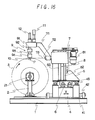
- Fig. 16 is a side view of the apparatus of the third embodiment.
- a front view of the third embodiment is omitted because it is same as the front view of the first embodiment (Fig. 2).
- the numeral 1 indicates a bed
- the numeral 2 indicates a tyre support provided on the bed 1
- a tyre 3 is mounted to a tyre supporting shaft 21 and is rotated by a motor.
- the numeral 4 indicates a base which is received by a rail 41 on the bed 1 and allowed to move being driven by a motor which is not shown in the drawings along a guide bar 42 in the direction of X-axis perpendicularly to the central axis of the tyre support 2.
- the base 4 can be fixed if the distance between the base 4 and the tyre support 2 is set at a prespecified distance.
- the numeral 5 indicates a laterally travelling stage which is placed on the base 4 and is allowed to move along a rail 43 in the direction of Y-axis in parallel with the tyre supporting shaft 21 and the numeral 6 indicates a laterally driving device for the laterally travelling stage 5.
- the laterally driving device 6 employs the same construction as that shown in Fig. 3.
- the numeral 7 indicates a radially travelling stage and the numeral 8 indicates a radially driving device which moves the radially travelling stage 7 in the direction of Z-axis perpendicularly to the tyre supporting shaft 21.
- the radially driving device 8 has a radially driving shaft 82 which is supported in vertical posture by the laterally travelling stage 5 and comprises a feed screw rotated by a driving motor 81, and which moves the radially travelling stage 5 upwardly and downwardly along a guide shaft 52.
- the numeral 71 indicates a rotating arm which is attached to an arm supporting shaft 72 projecting in the direction of X-axis from the radially travelling stage 7 and is rotated around a central axis 73 of the arm supporting shaft 72 in the direction of the arrow A shown in Fig. 2 by a motor which is not shown in the drawing.
- the numeral 9 indicates a cutter supporting unit attached in such a manner that the cutter supporting unit 9 projects perpendicularly toward the central axis 73 from the rotating arm 71.
- the cutter supporting unit 9 employs a construction wherein a cutter supporting frame 92 is attached to a supporting rod 91 supported by the rotating arm 71, a cutter holder 94 is attached to the cutter supporting frame 92 with an insulating member 93 being disposed therebetween, a cutter 10 is removably attached to the cutter holder 94 in such a manner that a cutting point P is located on the extended line from the central axis 73, and the cutter 10 is heated up by an electric power supply unit which is not shown in the drawing.
- the numeral 11 indicates a motor which rotates the cutter supporting unit 9 to change the direction of the cutter 10.
- the numeral 12 indicates an actuator which provide up-down movement of the cutter supporting unit 9 to make the cutter 10 positioned on the central axis 73.
- the device shown in Fig. 6 and Fig. 7 can be employed instead of the device shown in Fig. 3.
- the above grooving apparatus explained as the third embodiment employs a construction wherein a cutter is located above a tyre and is moved in up-down direction
- the present invention can be applied to another type of apparatus wherein a cutter is located in front of or behind a tyre and is moved in a horizontal direction perpendicularly to a tyre supporting shaft.
- the correction motor can be a motor having a small capacity and can be operated at a low speed because the correction motor only have to provide a small correction of the cutter position.
- lateral deflection sensors 13 may be provided on either side of the tyre to correct the cutter position based on the detected values on both sides.
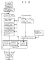
- FIG. 17 there is explained hereinafter an operation for correcting a cutter position using the apparatus of the third embodiment, in which a deflection of a tyre is detected during the grooving operation and the detected deflection data is collected to be incorporated into calculation.
- a position of an origin of each operating shaft is specified based on a command from a computer, which is not shown in the drawings, appropriately for a selected grooving pattern.
- Control values for a tyre without deflections have been given to a reference program of the computer as an input and the direction of the cutter 10 is set by the motor 11 so as to agree with the cutting direction in accordance with the reference program.
- the tyre 3 is rotated in the direction of the arrow (Fig. 16) by the motor 22, and concurrently the driving motor 81 of the radially driving device 8 for the radially travelling stage 7 is operated, then the radially travelling stage 7 is moved downwardly along the direction of Z-axis by the rotational movement of the radially driving shaft 82 with the assistance of the female threaded body 85, so that the cutter 10 which has been heated up by electric power supply cuts in the tyre 3.
- the driving motor 61 of the laterally driving device 6 is moved in accordance with a prespecified groove shape under the control of the reference program, and thus the lateral movement of the cutter 10 is controlled by the movement of the laterally travelling stage 5 in the direction of Y-axis driven by the rotational movement of the laterally driving shaft 62, so that the prespecified grooving is carried out.
- the lateral deflection E2 is detected by the lateral deflection detector 13.
- the correction motor 63 of the laterally driving device 6 is controlled by the correction program based on the detected deflection value, and thus, in case of the example of the laterally driving device, the female threaded body 65 is rotated by the laterally correction shaft 64 with the assistance of the driving gear 67 and the driven gear 68, so that the cutter position is corrected to a position shown by a dotted line in Fig. 10 by the lateral movement in the direction of Y-axis of the laterally travelling stage 5. Accordingly a distance M from the tyre center to the cutter position is kept constantly.
- the laterally correction shaft 64 is rotated by the rotation of the correction motor 63, and thus the laterally travelling stage 5 is moved with the assistance of the female threaded body 604.
- the lateral deflection of the tyre is detected and the position of the laterally travelling stage is controlled by the laterally driving shaft under the control of the reference program and is adjusted in accordance with the correction program during the grooving operation.
- the cutter position is adjusted according to the lateral deflection E2 of the tyre during the grooving operation, and also the cutter position is adjusted according to the lateral diflection E2 of the tyre, and therefore the position of the groove relative to the tyre center is kept constantly along the entire periphery of the tyre.
- FIG. 18 there is explained another example of operation using the grooving apparatus of the third embodiment, wherein a tyre is rotated prior to the grooving operation and the deflections of the tyre at any rotational positions are detected and stored in advance, and the stored deflection data is picked up in the grooving operation to be used for calculation so that the correction of the cutter position is carried out.
- the lateral deflection sensor 13 is arranged so as to be faced to the tyre buttress.
- the tyre 3 is rotated at a low speed and an origin for a numerical control is set at the origin mark. Starting from this condition, the tyre 3 is rotated to make one revolution, and during this rotation the detected values by the lateral deflection sensor 13 are stored in a memory together with corresponding rotational angular positions.
- the tyre supporting shaft 21 is rotated and concurrently the cutter 10 is controlled by a plurality of operating shafts such as a laterally driving shaft, a radially driving shaft, a rotating shaft etc. under the control of the reference program of the numerical control device.
- the cutter is moved downwardly to be brought into contact with the prespecified position of the tyre.
- the cutter has been heated up, and a prespecified grooving operation is carried out according to the rotational angular position with respect to the origin with a prespecified locus being formed.
- the stored deflection data is picked up from the memory according to the rotational angular position of the tyre, and the correction value from the correction program is calculated in accordance with a correction program control command from the reference program.
- the stored lateral deflection data is picked up from the memory according to the rotational angular position on the periphery of the buttress, and the correction motor 63 of the laterally driving device 6 is operated based on the lateral deflection correction value calculated by the correction program.
- the laterally correction shaft 64 is rotated and the movement caused by the correction program is incorporated into the movement caused by the reference program for the lateral movement of the cutter 10.
- the third embodiment of the apparatus for compensating deflection of the present invention employs a construction wherein the apparatus comprises the laterally driving shaft to move the cutter in parallel with the tyre supporting shaft, the radially driving shaft to move the cutter perpendicularly to the tyre supporting shaft and the detector to detect the lateral deflection of the tyre, and the laterally driving shaft and the radially driving shaft are controlled by the reference movement, and concurrently the cutter movement is corrected by superposing the correction movement according to the detected value of the detector on the reference movement. Therefore, the groove positions relative to the respective tyre tread centers of tyres can be kept constant to provide satisfactory running performance even if there are lateral deflections.
- the reference movement is always controlled based on the prespecified value by the reference program and the correction movement based on the detected deflection value can be superposed on the standard movement by the separate correction program, the structure of the program can be simplified and the apparatus can be made small. Further, the correction is performed surely and the productivity and yield are improved.
Landscapes
- Engineering & Computer Science (AREA)
- Mechanical Engineering (AREA)
- Tyre Moulding (AREA)
Applications Claiming Priority (6)
| Application Number | Priority Date | Filing Date | Title |
|---|---|---|---|
| JP322202/87 | 1987-12-19 | ||
| JP62322202 | 1987-12-19 | ||
| JP63134026A JPH01301233A (ja) | 1988-05-30 | 1988-05-30 | タイヤのグルービング装置およびグルービング方法 |
| JP63134027A JPH0387246A (ja) | 1988-05-30 | 1988-05-30 | タイヤのグルービング装置およびグルービング方法 |
| JP134027/88 | 1988-05-30 | ||
| JP134026/88 | 1988-05-30 |
Publications (3)
| Publication Number | Publication Date |
|---|---|
| EP0324959A2 true EP0324959A2 (de) | 1989-07-26 |
| EP0324959A3 EP0324959A3 (en) | 1990-11-14 |
| EP0324959B1 EP0324959B1 (de) | 1994-12-07 |
Family
ID=27316798
Family Applications (1)
| Application Number | Title | Priority Date | Filing Date |
|---|---|---|---|
| EP88121255A Expired - Lifetime EP0324959B1 (de) | 1987-12-19 | 1988-12-19 | Verfahren und Vorrichtung zum Korrigieren von Reifenverformungen beim Profilschneiden |
Country Status (4)
| Country | Link |
|---|---|
| US (2) | US5005628A (de) |
| EP (1) | EP0324959B1 (de) |
| AU (1) | AU606487B2 (de) |
| DE (1) | DE3852388T2 (de) |
Cited By (4)
| Publication number | Priority date | Publication date | Assignee | Title |
|---|---|---|---|---|
| EP0381777A4 (en) * | 1988-07-28 | 1990-12-12 | Sumitomo Rubber Industries, Co. Ltd | Tire grooving apparatus and method |
| EP1186402A3 (de) * | 2000-09-07 | 2003-10-01 | Bridgestone Corporation | Verfahren und Vorrichtung zum Einschneiden von Rohreifen |
| CN112208126A (zh) * | 2019-07-12 | 2021-01-12 | 通伊欧轮胎株式会社 | 输送装置及轮胎成型装置 |
| EP4265403A1 (de) * | 2022-04-22 | 2023-10-25 | maakwi GmbH | Reifennachschneidemaschine |
Families Citing this family (15)
| Publication number | Priority date | Publication date | Assignee | Title |
|---|---|---|---|---|
| EP0372090B1 (de) * | 1988-06-10 | 1994-03-30 | Sumitomo Rubber Industries Limited | Vorrichtung zum herstellen von riefen in reifen |
| US5193600A (en) * | 1988-07-28 | 1993-03-16 | Sumitomo Rubber Industries, Ltd. | Tire grooving apparatus and method |
| US9011203B2 (en) | 2007-03-29 | 2015-04-21 | Michelin Recherche Et Technique S.A. | Retread tire buffing with multiple response curves |
| WO2008121141A1 (en) * | 2007-03-29 | 2008-10-09 | Societe De Technologie Michelin | Retread tire buffing with multiple response curves |
| MX2009013124A (es) * | 2007-06-28 | 2010-01-15 | Michelin Rech Tech | Determinacion del radio de pulido durante el pulido de neumaticos. |
| BRPI0721804A2 (pt) * | 2007-06-28 | 2013-05-21 | Michelin Soc Tech | mÉtodo para corrigir um desbaste da banda de rodagem de uma coroa de um pneu, e, mÁquina de desbaste de pneu |
| US8523635B2 (en) * | 2007-06-29 | 2013-09-03 | Michelin Recherche Et Technique S.A. | Tire buffing debris collecting system |
| JP4934745B2 (ja) * | 2007-09-28 | 2012-05-16 | ミシュラン ルシェルシュ エ テクニーク ソシエテ アノニム | 更生中におけるクラウン層ばらつきの修正 |
| CN103009426A (zh) * | 2011-09-26 | 2013-04-03 | 北京橡胶工业研究设计院 | 轮胎成型机多自由度可调裁切装置 |
| WO2014100208A1 (en) * | 2012-12-19 | 2014-06-26 | Bridgestone Americas Tire Operations, Llc | Apparatus and method for preparing a sample from components internal to a tire |
| JP5831592B2 (ja) * | 2014-05-09 | 2015-12-09 | 横浜ゴム株式会社 | タイヤのトリミング装置および方法 |
| US20160046091A1 (en) * | 2014-08-12 | 2016-02-18 | Caterpillar Inc. | Cutter, cutter system, and method for severing elastomeric material from non-pneumatic tire |
| CN107791551A (zh) * | 2016-08-31 | 2018-03-13 | 山东豪迈机械科技股份有限公司 | 轮胎花纹自动加工系统及其热切主轴单元 |
| CN112757367A (zh) * | 2021-03-03 | 2021-05-07 | 无锡益联机械有限公司 | 一种子轮胎胶片自动切割机 |
| CN113021861B (zh) * | 2021-03-24 | 2022-12-27 | 山东省三利轮胎制造有限公司 | 一种轮胎胎纹的成型设备 |
Family Cites Families (13)
| Publication number | Priority date | Publication date | Assignee | Title |
|---|---|---|---|---|
| US3426828A (en) * | 1966-04-11 | 1969-02-11 | Peter C Neilsen | Tire tread cutting apparatus and method |
| US3835591A (en) * | 1973-05-14 | 1974-09-17 | Goodrich Co B F | Method and apparatus for correcting dimensional variation in a rotating tire |
| FR2366122A1 (fr) * | 1976-10-04 | 1978-04-28 | Michelin & Cie | Machine pour tailler des rainures dans la bande de roulement de pneumatiques |
| US4095374A (en) * | 1977-06-29 | 1978-06-20 | Uniroyal, Inc. | Method and apparatus for improved tire uniformity grinding and measuring |
| FR2403183A2 (fr) * | 1977-09-19 | 1979-04-13 | Michelin & Cie | Machine pour tailler des rainures dans la bande de roulement de pneumatiques |
| US4237955A (en) * | 1979-01-25 | 1980-12-09 | Brad Ragan, Inc. | Apparatus and method for grooving tires |
| US4782881A (en) * | 1980-04-16 | 1988-11-08 | The Goodyear Tire & Rubber Company | Method and apparatus for grooving tire tread |
| JPS61177232A (ja) * | 1985-02-04 | 1986-08-08 | Sumitomo Rubber Ind Ltd | タイヤのグル−ビング装置 |
| JPS6274635A (ja) * | 1985-09-30 | 1987-04-06 | Bridgestone Corp | タイヤのシエ−ビング装置 |
| US4674380A (en) * | 1986-01-29 | 1987-06-23 | David Hecht | Apparatus for cutting ribbon |
| US4663889A (en) * | 1986-07-14 | 1987-05-12 | The Firestone Tire & Rubber Company | Apparatus and method for grinding sidewall areas of tires |
| EP0372090B1 (de) * | 1988-06-10 | 1994-03-30 | Sumitomo Rubber Industries Limited | Vorrichtung zum herstellen von riefen in reifen |
| WO1990000965A1 (fr) * | 1988-07-28 | 1990-02-08 | Sumitomo Rubber Industries, Ltd. | Dispositif et procede de sculptage de pneus |
-
1988
- 1988-12-16 AU AU26984/88A patent/AU606487B2/en not_active Ceased
- 1988-12-19 EP EP88121255A patent/EP0324959B1/de not_active Expired - Lifetime
- 1988-12-19 DE DE3852388T patent/DE3852388T2/de not_active Expired - Fee Related
-
1989
- 1989-11-06 US US07/432,405 patent/US5005628A/en not_active Expired - Fee Related
-
1990
- 1990-08-24 US US07/572,278 patent/US5067539A/en not_active Expired - Fee Related
Cited By (9)
| Publication number | Priority date | Publication date | Assignee | Title |
|---|---|---|---|---|
| EP0381777A4 (en) * | 1988-07-28 | 1990-12-12 | Sumitomo Rubber Industries, Co. Ltd | Tire grooving apparatus and method |
| US5144996A (en) * | 1988-07-28 | 1992-09-08 | Sumitomo Rubber Industries, Ltd. | Tire grooving apparatus and method |
| EP1186402A3 (de) * | 2000-09-07 | 2003-10-01 | Bridgestone Corporation | Verfahren und Vorrichtung zum Einschneiden von Rohreifen |
| US6951235B2 (en) | 2000-09-07 | 2005-10-04 | Bridgestone Corporation | Method and apparatus for forming carved groove of green tire |
| CN112208126A (zh) * | 2019-07-12 | 2021-01-12 | 通伊欧轮胎株式会社 | 输送装置及轮胎成型装置 |
| CN112208126B (zh) * | 2019-07-12 | 2022-06-10 | 通伊欧轮胎株式会社 | 输送装置及轮胎成型装置 |
| EP4265403A1 (de) * | 2022-04-22 | 2023-10-25 | maakwi GmbH | Reifennachschneidemaschine |
| EP4566778A2 (de) | 2022-04-22 | 2025-06-11 | Bear-Machines GmbH | Reifennachschneidemaschine und verfahren zum nachschneiden eines profils |
| EP4566778A3 (de) * | 2022-04-22 | 2025-09-10 | Bear-Machines GmbH | Reifennachschneidemaschine und verfahren zum nachschneiden eines profils |
Also Published As
| Publication number | Publication date |
|---|---|
| EP0324959B1 (de) | 1994-12-07 |
| US5005628A (en) | 1991-04-09 |
| AU2698488A (en) | 1989-06-22 |
| US5067539A (en) | 1991-11-26 |
| EP0324959A3 (en) | 1990-11-14 |
| AU606487B2 (en) | 1991-02-07 |
| DE3852388D1 (de) | 1995-01-19 |
| DE3852388T2 (de) | 1995-04-27 |
Similar Documents
| Publication | Publication Date | Title |
|---|---|---|
| EP0324959A2 (de) | Verfahren und Vorrichtung zum Korrigieren von Reifenverformungen beim Profilschneiden | |
| EP0254913B1 (de) | Einrichtung und Verfahren zum Schleifen der Seitenwände von Reifen | |
| US5161333A (en) | Device for recalibrating a machine for grinding ophthalmic glasses | |
| US5901595A (en) | Apparatus for machining a workpiece | |
| CA2060109C (en) | Method and apparatus for buffing a tire sidewall | |
| US5035554A (en) | Method for determining the radius described by a tool | |
| WO2001094059A1 (en) | On-vehicle disk brake lathe | |
| EP0359591B1 (de) | Vorrichtung zur Formung von Stangen in gerader kreisförmiger Zylinderform | |
| US7507142B2 (en) | Eyeglass lens processing apparatus | |
| US5144996A (en) | Tire grooving apparatus and method | |
| US5193600A (en) | Tire grooving apparatus and method | |
| EP0379427B1 (de) | Rohling-Messapparat für Linsenschleifmaschine | |
| JP2546062B2 (ja) | 長尺軸の外面研削装置 | |
| JP2009113161A (ja) | 研削方法および研削装置 | |
| EP0950214B1 (de) | Verfahren zur steuerung einer werkzeugmaschine | |
| JPH0515209B2 (de) | ||
| JPH08192358A (ja) | 研削盤による加工方法およびその研削盤 | |
| JPH0387246A (ja) | タイヤのグルービング装置およびグルービング方法 | |
| EP0514180A2 (de) | Automatisches Trimmverfahren und dafür verwendetes Gerät | |
| GB2154163A (en) | Cylindrical grinding machine having position detection probe | |
| JP2613455B2 (ja) | インゴットの自動芯出し・セット装置及び自動円筒研磨装置 | |
| JPH0541430B2 (de) | ||
| GB2310154A (en) | Cylindrical grinding | |
| JPH0777715B2 (ja) | 偏平材料の裁断装置 | |
| KR102561730B1 (ko) | 나이프 갭 자동조절이 가능한 사이드 트리머 |
Legal Events
| Date | Code | Title | Description |
|---|---|---|---|
| PUAI | Public reference made under article 153(3) epc to a published international application that has entered the european phase |
Free format text: ORIGINAL CODE: 0009012 |
|
| AK | Designated contracting states |
Kind code of ref document: A2 Designated state(s): DE FR GB |
|
| PUAL | Search report despatched |
Free format text: ORIGINAL CODE: 0009013 |
|
| AK | Designated contracting states |
Kind code of ref document: A3 Designated state(s): DE FR GB |
|
| 17P | Request for examination filed |
Effective date: 19901221 |
|
| 17Q | First examination report despatched |
Effective date: 19930325 |
|
| GRAA | (expected) grant |
Free format text: ORIGINAL CODE: 0009210 |
|
| AK | Designated contracting states |
Kind code of ref document: B1 Designated state(s): DE FR GB |
|
| REF | Corresponds to: |
Ref document number: 3852388 Country of ref document: DE Date of ref document: 19950119 |
|
| ET | Fr: translation filed | ||
| PLBE | No opposition filed within time limit |
Free format text: ORIGINAL CODE: 0009261 |
|
| STAA | Information on the status of an ep patent application or granted ep patent |
Free format text: STATUS: NO OPPOSITION FILED WITHIN TIME LIMIT |
|
| 26N | No opposition filed | ||
| PGFP | Annual fee paid to national office [announced via postgrant information from national office to epo] |
Ref country code: FR Payment date: 20011212 Year of fee payment: 14 |
|
| PGFP | Annual fee paid to national office [announced via postgrant information from national office to epo] |
Ref country code: GB Payment date: 20011219 Year of fee payment: 14 |
|
| REG | Reference to a national code |
Ref country code: GB Ref legal event code: IF02 |
|
| PGFP | Annual fee paid to national office [announced via postgrant information from national office to epo] |
Ref country code: DE Payment date: 20020109 Year of fee payment: 14 |
|
| PG25 | Lapsed in a contracting state [announced via postgrant information from national office to epo] |
Ref country code: GB Free format text: LAPSE BECAUSE OF NON-PAYMENT OF DUE FEES Effective date: 20021219 |
|
| PG25 | Lapsed in a contracting state [announced via postgrant information from national office to epo] |
Ref country code: DE Free format text: LAPSE BECAUSE OF NON-PAYMENT OF DUE FEES Effective date: 20030701 |
|
| GBPC | Gb: european patent ceased through non-payment of renewal fee |
Effective date: 20021219 |
|
| PG25 | Lapsed in a contracting state [announced via postgrant information from national office to epo] |
Ref country code: FR Free format text: LAPSE BECAUSE OF NON-PAYMENT OF DUE FEES Effective date: 20030901 |
|
| REG | Reference to a national code |
Ref country code: FR Ref legal event code: ST |