EP0324975A2 - Système de transmission pour une communication téléphonique ou une transmission de données - Google Patents
Système de transmission pour une communication téléphonique ou une transmission de données Download PDFInfo
- Publication number
- EP0324975A2 EP0324975A2 EP88121664A EP88121664A EP0324975A2 EP 0324975 A2 EP0324975 A2 EP 0324975A2 EP 88121664 A EP88121664 A EP 88121664A EP 88121664 A EP88121664 A EP 88121664A EP 0324975 A2 EP0324975 A2 EP 0324975A2
- Authority
- EP
- European Patent Office
- Prior art keywords
- current
- signal
- generator
- telephone
- microphone
- Prior art date
- Legal status (The legal status is an assumption and is not a legal conclusion. Google has not performed a legal analysis and makes no representation as to the accuracy of the status listed.)
- Withdrawn
Links
Images

Classifications
-
- H—ELECTRICITY
- H04—ELECTRIC COMMUNICATION TECHNIQUE
- H04L—TRANSMISSION OF DIGITAL INFORMATION, e.g. TELEGRAPHIC COMMUNICATION
- H04L5/00—Arrangements affording multiple use of the transmission path
- H04L5/14—Two-way operation using the same type of signal, i.e. duplex
- H04L5/1423—Two-way operation using the same type of signal, i.e. duplex for simultaneous baseband signals
-
- H—ELECTRICITY
- H04—ELECTRIC COMMUNICATION TECHNIQUE
- H04B—TRANSMISSION
- H04B14/00—Transmission systems not characterised by the medium used for transmission
- H04B14/002—Transmission systems not characterised by the medium used for transmission characterised by the use of a carrier modulation
- H04B14/004—Amplitude modulation
Definitions
- This invention concerns a transmission system for telephone communications comprising at least two telephone set, each provided with a microphone and a receiver and/or loudspeaker, a telephone line connecting the sets over two conductors in order to form a current loop, an AC generator attached to the current loop as well as current path switching circuits, which are adapted to steer the current to be routed during the positive half-cycles generated by the generator via the microphone circuit of the first set and the receiver and/or loudspeaker circuit of the second set as well as to steer the current during the negative half-cycles via the receiver and/or loudspeaker circuit of the first set and the microphone circuit of the second set, whereby voice transmission takes place by sampling the microphone signals of the interconnected telephone sets and transmitting the alternate signal samples superimposed on the generator signal so that the microphone signal of the first set is superimposed on the positive half-cycles of the generator signal while the microphone signal of the second set is superimposed on the negative half-cycles of the generator signal.
- the invention also concerns a transmission system for data transfer, which differs from the transmission system for telephone communications only by replacing the telephone sets with modems, which incorporate interfaces for incoming and outgoing data signals.
- a general aim of the invention is to provide a transmission system for telephone communications, which system utilizes such a novel telephone communications format that offers simplification of the telephone set and switching equipment as well as simpler interfacing with digital transmission systems than possible so far.
- An application of the invention to data transmission aims to provide a modem with a significantly simplified construction.
- the telephone sets are powered over the same conductors that are used for the transmission of voice information.
- Voice signal transmission is implemented using bidirectional current signals.
- the voice signal directions are separated at the telephone set end with the help of so-called antisidetone network, and the signal levels are controlled by an automatic level control loop.
- a converter is required for each extension at the exchange end.
- communications is implemented using a pulse-coded signal transmitted over a two- or four-wire line.
- a compatible telephone set incorporates the necessary analog and digital signal converters as well as the PCM interface.
- Intercom systems require a loudspeaker function for establishing a connection, whereby the antisidetone network used in conventional telephone technology is often ineffective and necessitates the use of an alternating simplex communication scheme, or alternatively, separate lines for incoming and outgoing voice signals.
- a drawback of analog telephones is the high cost of a high-quality antisidetone network, requiring a relatively complex circuitry in, e.g., a loudspeaker telephone, while yet remaining far from the desired ideal performance of an automatic level control in differing conditions. Further, complicated subscriber line converters are required in conjunction with digital telephone exchanges.
- intercom systems require several line pairs for configuring a connection.
- a bidirectional intercom system known from a US patent publication requires at least five conductors between the sets, while hybrid transformers are used to superimpose an AC voltage on the current loop of the connection.
- the object of the invention is to provide a transmission system for telephone communications, in which system the use of a novel, simple telephone communications format makes it possible to achieve an almost ideal antisidetone network in combination with level control, combined with a remarkably simplified interfacing to digital technology, thus simplifying the circuitry of a telephone set for both its basic as well as loudspeaker functions so that a significant reduction in the cost of a telephone set results.
- This object of the invention is achieved in accordance with the invention therein that the current control elements described above are connected between a current loop comprising but two conductors, and a microphone circuit and a receiver and/or loudspeaker circuit at the telephone sets so as to prevent bidirectional current paths between the microphone circuit and the receiver and/or loudspeaker circuit within a single telephone set, while allowing only a unidirectional current path of the current loop through said circuits.
- a similar application of the invention to a data transmission system is possible through replacing the telephone sets by modems as stated in claim 2 later.
- a sampling frequency of at least twice the highest signal frequency component provides information transfer at no essential corruption of the signal.
- a preferred sampling frequency is in the range 8...20 kHz. Preliminary tests have been run using an 8 kHz sampling frequency.
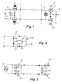
- the telephone exchange section comprises a DC voltage supply 1, which provides power feed over the line to the telephone set via a rectifier bridge 8.
- the DC voltage supply is not indispensable but instead, power feed can be arranged using an AC generator 2.
- the basic function of the square-wave generating AC generator 2 is to feed a so-called sampling frequency onto the line that controls switches 3, 4, 6, and 7 at both the exchange section and the telephone set.
- the frequency generated by the generator 2, namely the sampling frequency may be set equal to that used in PCM equipment, or 8 kHz.
- the generator 2 is also used for sending the ring signal at a lower frequency.
- Alternation between speech directions is achieved by switching between the ON and OFF states of the switches in synchronization with the sampling frequency.
- the generator 2 controls the switches 3 and 4, while at the telephone set a bandpass filter 5 controls the switches 6 and 7.
- the center frequency of the bandpass filter 5 is set equal to the sampling frequency.
- the filter 5 may be replaced by simple diodes when the DC supply 1 is omitted.
- the positive half-cycle of the sampling frequency switches onto the line the outgoing signal amplifier of the exchange equipment and the incoming signal amplifier of the telephone set, thus making it possible to transfer the signal sample in a current signal form.
- the negative half-cycles of the sampling frequency are used in a similar manner for transferring the speech signal samples.
- Fig. 2 Illustrated in Fig. 2 is a circuit diagram of a fully functional telephone set implemented omitting the bandpass filter which is then replaced by diodes 11.
- the telephone set comprises the following basic components: a hook switch 12, dial switches 13, a ring circuit 14, and a conventional receiver 10 and a microphone 9.
- Level control is implemented at the exchange equipment side by means of a slowly-varying constant current control, which is insensitive to audio-frequency signal components.
- a transmission system according to the invention for telephone communications can be used in a multitude of applications that require speakerphone functions yet avoiding singing, including such as access control intercoms, door entrance intercoms, office intercoms, lift intercoms and distress call telephone in noninstitutional care.
- Figure 3 illustrates a simplified circuit diagram of an apparatus suitable for these applications.
- the diodes 11 are configured to act as current switch elements, which during the first half-cycle of the generator 2 frequency steer the current via the microphone of the first telephone set as well as via the loudspeaker 10′ of the second telephone set, while during the negative half-cycles the current is steered via the loudspeaker 10′ of the first telephone set and via the microphone 9 of the second telephone set.
- this configuration implements voice transmission by sampling of the microphone signals superimposed on the generator signal so that the microphone signal of the first telephone set is superimposed on the positive half-cycles of the generator signal, while the microphone signal of the second telephone set is superimposed on the negative half-cycles of the generator signal.
- the loudspeakers 10′ are provided with amplifiers for boosting the current signal level.
- the invention can be used for implementing a remarkably simple modem for data transmission. Illustrated in the embodiment shown in Figure 4 are two modems communicating over a paired line. Both modems incorporate an interface 11a for the incoming data signal and an interface 11b for the outgoing data signal as well as diodes 11 for steering the loop current according to its polarity to be routed via either the incoming signal interface or the outgoing signal interface, respectively.
- the sampling frequency is created by the AC generator 2.
- the modems are attached via logic-level compatible serial interfaces 15 to computer apparatuses. It will be evident from the foregoing that data transmission occurs in the loop formed by paired line in a simultaneously bidirectional manner using a similar sampling and current switching principle as depicted in conjunction with the description elucidating the telephone communications system.
Landscapes
- Engineering & Computer Science (AREA)
- Signal Processing (AREA)
- Computer Networks & Wireless Communication (AREA)
- Interconnected Communication Systems, Intercoms, And Interphones (AREA)
- Telephonic Communication Services (AREA)
- Telephone Function (AREA)
Applications Claiming Priority (2)
| Application Number | Priority Date | Filing Date | Title |
|---|---|---|---|
| FI880189A FI78373C (fi) | 1988-01-18 | 1988-01-18 | Telefontrafik- eller dataoeverfoeringssystem. |
| FI880189 | 1988-01-18 |
Publications (2)
| Publication Number | Publication Date |
|---|---|
| EP0324975A2 true EP0324975A2 (fr) | 1989-07-26 |
| EP0324975A3 EP0324975A3 (fr) | 1990-11-28 |
Family
ID=8525733
Family Applications (1)
| Application Number | Title | Priority Date | Filing Date |
|---|---|---|---|
| EP19880121664 Withdrawn EP0324975A3 (fr) | 1988-01-18 | 1988-12-24 | Système de transmission pour une communication téléphonique ou une transmission de données |
Country Status (6)
| Country | Link |
|---|---|
| US (1) | US4989236A (fr) |
| EP (1) | EP0324975A3 (fr) |
| JP (1) | JPH01245662A (fr) |
| DK (1) | DK18989A (fr) |
| FI (1) | FI78373C (fr) |
| NO (1) | NO172828C (fr) |
Families Citing this family (31)
| Publication number | Priority date | Publication date | Assignee | Title |
|---|---|---|---|---|
| JPH02280422A (ja) * | 1989-04-20 | 1990-11-16 | Nec Corp | 音声会議装置用エコーキャンセラのトレーニング方法 |
| FR2704703B1 (fr) * | 1993-04-28 | 1995-06-30 | Gemplus Card Int | Appareil d'exploitation de signaux electriques. |
| US6389135B1 (en) * | 1998-09-25 | 2002-05-14 | Conexant Systems, Inc. | Method and apparatus for deriving power from a clock signal coupled through capacitors |
| US6556677B1 (en) * | 1999-05-27 | 2003-04-29 | William Christopher Hardy | Single-ended echo cancellation system and method |
| US9719302B2 (en) | 2008-08-20 | 2017-08-01 | Foro Energy, Inc. | High power laser perforating and laser fracturing tools and methods of use |
| RU2522016C2 (ru) * | 2008-08-20 | 2014-07-10 | Форо Энерджи Инк. | Способ и система для проходки ствола скважины с использованием лазера большой мощности |
| US9138786B2 (en) | 2008-10-17 | 2015-09-22 | Foro Energy, Inc. | High power laser pipeline tool and methods of use |
| US8571368B2 (en) | 2010-07-21 | 2013-10-29 | Foro Energy, Inc. | Optical fiber configurations for transmission of laser energy over great distances |
| US9669492B2 (en) | 2008-08-20 | 2017-06-06 | Foro Energy, Inc. | High power laser offshore decommissioning tool, system and methods of use |
| US9562395B2 (en) | 2008-08-20 | 2017-02-07 | Foro Energy, Inc. | High power laser-mechanical drilling bit and methods of use |
| US9664012B2 (en) | 2008-08-20 | 2017-05-30 | Foro Energy, Inc. | High power laser decomissioning of multistring and damaged wells |
| US9242309B2 (en) | 2012-03-01 | 2016-01-26 | Foro Energy Inc. | Total internal reflection laser tools and methods |
| US9244235B2 (en) | 2008-10-17 | 2016-01-26 | Foro Energy, Inc. | Systems and assemblies for transferring high power laser energy through a rotating junction |
| US9080425B2 (en) | 2008-10-17 | 2015-07-14 | Foro Energy, Inc. | High power laser photo-conversion assemblies, apparatuses and methods of use |
| US9360631B2 (en) | 2008-08-20 | 2016-06-07 | Foro Energy, Inc. | Optics assembly for high power laser tools |
| US9347271B2 (en) * | 2008-10-17 | 2016-05-24 | Foro Energy, Inc. | Optical fiber cable for transmission of high power laser energy over great distances |
| US9267330B2 (en) | 2008-08-20 | 2016-02-23 | Foro Energy, Inc. | Long distance high power optical laser fiber break detection and continuity monitoring systems and methods |
| US9089928B2 (en) | 2008-08-20 | 2015-07-28 | Foro Energy, Inc. | Laser systems and methods for the removal of structures |
| US9027668B2 (en) | 2008-08-20 | 2015-05-12 | Foro Energy, Inc. | Control system for high power laser drilling workover and completion unit |
| US8627901B1 (en) | 2009-10-01 | 2014-01-14 | Foro Energy, Inc. | Laser bottom hole assembly |
| US10301912B2 (en) * | 2008-08-20 | 2019-05-28 | Foro Energy, Inc. | High power laser flow assurance systems, tools and methods |
| US8684088B2 (en) | 2011-02-24 | 2014-04-01 | Foro Energy, Inc. | Shear laser module and method of retrofitting and use |
| US8783361B2 (en) | 2011-02-24 | 2014-07-22 | Foro Energy, Inc. | Laser assisted blowout preventer and methods of use |
| US8720584B2 (en) | 2011-02-24 | 2014-05-13 | Foro Energy, Inc. | Laser assisted system for controlling deep water drilling emergency situations |
| US8783360B2 (en) | 2011-02-24 | 2014-07-22 | Foro Energy, Inc. | Laser assisted riser disconnect and method of use |
| US9845652B2 (en) | 2011-02-24 | 2017-12-19 | Foro Energy, Inc. | Reduced mechanical energy well control systems and methods of use |
| CA2808214C (fr) | 2010-08-17 | 2016-02-23 | Foro Energy Inc. | Systemes et structures d'acheminement destines a une emission laser longue distance a haute puissance |
| WO2012116155A1 (fr) | 2011-02-24 | 2012-08-30 | Foro Energy, Inc. | Moteur électrique pour forage laser-mécanique |
| WO2012167102A1 (fr) | 2011-06-03 | 2012-12-06 | Foro Energy Inc. | Connecteurs optiques robustes à fibre laser d'énergie élevée passivement refroidie et procédés d'utilisation |
| US9340405B2 (en) | 2012-01-26 | 2016-05-17 | Progressive International Electronics Inc. | Fuel transaction tracking system |
| US10221687B2 (en) | 2015-11-26 | 2019-03-05 | Merger Mines Corporation | Method of mining using a laser |
Family Cites Families (8)
| Publication number | Priority date | Publication date | Assignee | Title |
|---|---|---|---|---|
| FR833596A (fr) * | 1937-06-24 | 1938-10-25 | Systèmes de multiplication des communications télégraphiques ou téléphoniques | |
| US2980769A (en) * | 1957-05-06 | 1961-04-18 | Westinghouse Electric Corp | Bidirectional multiplex transistor communication apparatus |
| FR2102614A5 (fr) * | 1970-08-06 | 1972-04-07 | Barok Albert | |
| NO134477C (fr) * | 1974-10-29 | 1976-10-13 | Manus Max | |
| DE2644364C3 (de) * | 1976-10-01 | 1981-07-16 | Telefonbau Und Normalzeit Gmbh, 6000 Frankfurt | Duplexfähiges Informationsübertragungsverfahren zwischen zwei über einen aus einem Verbindungsweg und einem Rückweg bestehenden Stromkreis miteinander verbundenen Datenstationen |
| US4326287A (en) * | 1980-06-30 | 1982-04-20 | International Business Machines Corp. | Two wire bi-directional digital telephone link |
| US4731798A (en) * | 1982-12-07 | 1988-03-15 | Josef Dirr | Method for transmitting information, in which the signals are coded as amplitudes of the half-waves or periods of a sinusoidal alternating current |
| US4595803A (en) * | 1984-02-02 | 1986-06-17 | The United States Of America As Represented By The United States Department Of Energy | Bidirectional amplifier |
-
1988
- 1988-01-18 FI FI880189A patent/FI78373C/fi not_active IP Right Cessation
- 1988-12-24 EP EP19880121664 patent/EP0324975A3/fr not_active Withdrawn
-
1989
- 1989-01-06 US US07/294,390 patent/US4989236A/en not_active Expired - Fee Related
- 1989-01-12 NO NO890132A patent/NO172828C/no unknown
- 1989-01-17 DK DK018989A patent/DK18989A/da not_active Application Discontinuation
- 1989-01-18 JP JP1010941A patent/JPH01245662A/ja active Pending
Also Published As
| Publication number | Publication date |
|---|---|
| NO172828B (no) | 1993-06-01 |
| US4989236A (en) | 1991-01-29 |
| FI78373C (fi) | 1989-07-10 |
| NO890132D0 (no) | 1989-01-12 |
| NO172828C (no) | 1993-09-08 |
| FI880189A0 (fi) | 1988-01-18 |
| DK18989A (da) | 1989-07-19 |
| JPH01245662A (ja) | 1989-09-29 |
| DK18989D0 (da) | 1989-01-17 |
| FI78373B (fi) | 1989-03-31 |
| NO890132L (no) | 1989-07-19 |
| EP0324975A3 (fr) | 1990-11-28 |
Similar Documents
| Publication | Publication Date | Title |
|---|---|---|
| US4989236A (en) | Transmission system for telephone communications or data transfer | |
| US4593389A (en) | Simultaneous voice and asynchronous data telephone | |
| US4759059A (en) | Analog telephone circuit for digital telephone system | |
| US4685129A (en) | Power transmission arrangement for telecommunications systems | |
| JPH04220023A (ja) | 専用電源網による組織内音声・データ通信の方法と装置 | |
| US4660219A (en) | Extension ringing arrangement key telephone system | |
| US6141414A (en) | Data access arrangement having combined remote hang-up/ring detection circuitry | |
| JPS61103356A (ja) | ボタン電話装置 | |
| US6005933A (en) | Method for communication with no power feed and exchange for realizing the method | |
| WO2000072568A9 (fr) | Procede interface telephone-ordinateur et appareil | |
| RU2106008C1 (ru) | Управляемая от эвм телекоммуникационная установка | |
| JPH0238550Y2 (fr) | ||
| KR100195434B1 (ko) | 키폰시스템 | |
| JP2002526986A (ja) | 電話加入者端において電話回線を信号処理装置に直流減結合接続させる装置 | |
| HUT64165A (en) | Circuit arrangement for telephone sets | |
| WO2001006668A1 (fr) | Dispositif ecouteur/microphone detachable sans fil | |
| JPS6378652A (ja) | 4線式アナログ加入者回路 | |
| JPS631288A (ja) | トランク回路 | |
| JPS6360691A (ja) | ボタン電話装置 | |
| JPS62161247A (ja) | インタ−ホン装置 | |
| JPS6317384B2 (fr) | ||
| JPS62271549A (ja) | デイジタル加入者線路の切替方式 | |
| JPS60165167A (ja) | システム異常時のシステム迂回方式 | |
| JPS61212925A (ja) | ボタン電話装置 | |
| JPH01309456A (ja) | 網制御装置 |
Legal Events
| Date | Code | Title | Description |
|---|---|---|---|
| PUAI | Public reference made under article 153(3) epc to a published international application that has entered the european phase |
Free format text: ORIGINAL CODE: 0009012 |
|
| AK | Designated contracting states |
Kind code of ref document: A2 Designated state(s): AT CH DE FR GB IT LI NL SE |
|
| PUAL | Search report despatched |
Free format text: ORIGINAL CODE: 0009013 |
|
| AK | Designated contracting states |
Kind code of ref document: A3 Designated state(s): AT CH DE FR GB IT LI NL SE |
|
| 17P | Request for examination filed |
Effective date: 19910508 |
|
| 17Q | First examination report despatched |
Effective date: 19930304 |
|
| STAA | Information on the status of an ep patent application or granted ep patent |
Free format text: STATUS: THE APPLICATION IS DEEMED TO BE WITHDRAWN |
|
| 18D | Application deemed to be withdrawn |
Effective date: 19930715 |