EP0325008B1 - Video-Abbildungssysteme - Google Patents
Video-Abbildungssysteme Download PDFInfo
- Publication number
- EP0325008B1 EP0325008B1 EP88300373A EP88300373A EP0325008B1 EP 0325008 B1 EP0325008 B1 EP 0325008B1 EP 88300373 A EP88300373 A EP 88300373A EP 88300373 A EP88300373 A EP 88300373A EP 0325008 B1 EP0325008 B1 EP 0325008B1
- Authority
- EP
- European Patent Office
- Prior art keywords
- line
- signal
- light
- modulated
- laser
- Prior art date
- Legal status (The legal status is an assumption and is not a legal conclusion. Google has not performed a legal analysis and makes no representation as to the accuracy of the status listed.)
- Expired - Lifetime
Links
Images




Classifications
-
- H—ELECTRICITY
- H04—ELECTRIC COMMUNICATION TECHNIQUE
- H04N—PICTORIAL COMMUNICATION, e.g. TELEVISION
- H04N5/00—Details of television systems
- H04N5/74—Projection arrangements for image reproduction, e.g. using eidophor
- H04N5/7416—Projection arrangements for image reproduction, e.g. using eidophor involving the use of a spatial light modulator, e.g. a light valve, controlled by a video signal
-
- G—PHYSICS
- G02—OPTICS
- G02F—OPTICAL DEVICES OR ARRANGEMENTS FOR THE CONTROL OF LIGHT BY MODIFICATION OF THE OPTICAL PROPERTIES OF THE MEDIA OF THE ELEMENTS INVOLVED THEREIN; NON-LINEAR OPTICS; FREQUENCY-CHANGING OF LIGHT; OPTICAL LOGIC ELEMENTS; OPTICAL ANALOGUE/DIGITAL CONVERTERS
- G02F1/00—Devices or arrangements for the control of the intensity, colour, phase, polarisation or direction of light arriving from an independent light source, e.g. switching, gating or modulating; Non-linear optics
- G02F1/01—Devices or arrangements for the control of the intensity, colour, phase, polarisation or direction of light arriving from an independent light source, e.g. switching, gating or modulating; Non-linear optics for the control of the intensity, phase, polarisation or colour
- G02F1/11—Devices or arrangements for the control of the intensity, colour, phase, polarisation or direction of light arriving from an independent light source, e.g. switching, gating or modulating; Non-linear optics for the control of the intensity, phase, polarisation or colour based on acousto-optical elements, e.g. using variable diffraction by sound or like mechanical waves
Definitions
- This invention relates to a video imaging system.
- Nd:Yag Q-switched lasers were chosen by Yamamoto.
- the infra red light emission which was converted into second harmonic waves by using an appropriate non-linear optical crystal, provided the necessary visible light.
- the 1.06-micron spectral line emission is converted into green light which has a wave length of approximately .534 microns.
- the 1.318-micron spectral line emission is converted into red light which has a wave length of approximately .660 microns. Because of the impractical operation, the .946-micron spectral line emission was not used to obtain the blue line. Instead, optical mixing of 1.32 microns and .660 microns was converted into an additional wave length of approximately .439 microns.
- the luminous efficiency of the red and blue lines, when taking the spectral response curve of the human retina into consideration, is so low that the amount of light needed is in excess of the limits imposed by the Nd:Yag laser family, although the reproducible color spectrum is excellent for low luminosity.
- the ultra-violet was achieved by parametric mixing of 1.06 microns and the second harmonic .534 microns, the sum frequency being .350 microns. This requires, however, additional green light in order to produce the blue. Accordingly, prior art systems make an impractical projector. Although the Nd:Yag has relatively good overall energy to light efficiency, the applicable mixing hinders the practical application.
- EP 0157791 discloses an alternative system to that described in U.S 3,818,129 and employs a copper vapour laser. Furthermore, “The Laser Guidebook”, by J.Hecht, McGraw-Hill, NY,1986, at chapter 12 discloses details of the high power and efficiency of metal vapour lasers.
- a video imaging system responsive to electrical signals representing an image
- a light source for at least one selected frequency, said source including at least one pulsed laser, an acousto-optical cell including a medium for sound transmittal having a first face facing said laser and an electrical signal to sound wave transducer mounted on a face other than said first face for producing sound waves which are non-colinear with but interact with the light from said laser; signal means for driving said transducer to produce sound waves modulated in amplitude, to correspond to the electrical signals for a line of the image; a projection surface; and sequential plane projection means for causing the light from said medium to impinge on the projection surface at a particular line position which corresponds to the ordinal position of the corresponding line of video data within said image, characterised in that said signal means includes a compression means for electronically reducing the time duration for a signal representing the line of the image, wherein said compression means includes first means for storing data at the real time rate of the electrical signals and second means
- the light source includes a plurality of pulsed lasers, wherein said lasers emit different monochromatic colours and there is further included a plurality of sound wave transducers, each of said transducers corresponding to one of said lasers and oriented to permit each of said monochromatic colours from said light sources to be modulated by said second waves from said one of said transducers, and said signal means including a plurality of signal sources, each of said sources corresponding to the electrical signals for said colour of a respective said laser for said line of image. There may be further included means for mixing said modulated colour signals.
- a method for displaying video images corresponding to an electrical signal representing the images on a projection surface comprising the steps of: receiving the signal; converting each line of the signal to sound waves; introducing the sound waves into a medium for transmission of sound waves; waiting until enough sound waves to represent a full line of image is contained within the medium; introducing at least one pulse of monochromatic light into the medium after the waiting step for a period less than the propagation of a pixel in the medium and at an angle which causes the monochromatic light to pass through the sound wave, whereby the monochromatic light is modulated; focusing the modulated light; and illuminating the portion of the projection surface corresponding to the line with the modulated line of monochromatic light, characterised in that after receiving said signal, and before converting said signal into sound waves, the signal is electronically compressed for reducing the time duration of a signal representing a line of the image, wherein the compression includes first the storage of data at the real time rate of the electrical signals and second the transmission of
- a video imaging system uses monochromatic light source, or sources, modulated by signals within an acoustic-optical cell or cells using an isotropic or anisotropic medium for modulation of the light from the light source or sources.
- monochromatic light source or sources
- an isotropic or anisotropic medium for modulation of the light from the light source or sources.
- metal vapour lasers are used for the monochromatic light source.
- shear wave propagation of the sound waves in an anisotropic acoustic-optical cell is preferred to reduce crystal size of the acoustic-optical cell.
- a data compression system for use with the acoustic-optical cell to reduce the time period required to propagate sound waves which have been modulated to correspond to the electrical signals which correspond to a line of image, is also disclosed to minimise the size of the crystal in the acoustic-optical or Bragg cell.
- Such video imaging system is used to project monochromatic or multi-coloured video images onto a projection surface by sequential line writing (plane projection) with sufficient resolution and brightness to substitute for and/or exceed the capabilities of conventional large and small screen imaging systems.
- metal vapor lasers such as gold at 627 nm for red, copper at 510 nm for green, and bismuth at 472 nm for blue is disclosed below. It has been discovered that metal vapor lasers have typically much higher wattage output efficiency than do continuous or non-metal pulsed lasers in the visible spectrum.
- the compression may be used in conjunction with the anisotropic crystals, as well as isotropic crystals.
- the length of a standard NTSC video raster scan line for example, is 63.5 micro-seconds including a blanking sync interval.
- the light source metal vapor laser
- the time length of the pulse may be less than or equal to the time required to write a pixel of information on the projection surface in real time ("pixel of time")
- the light which is to be modulated by means of acoustic-optical modulation need be introduced only after the entire line is compressed and fully propagated along the crystal; i.e., the modulated line of an RF signal is fully within and still travelling through the acoustic-optical crystal when the pulse of light occurs, the pulse occurring in less than a pixel of time.
- the pulse or light may be modulated to correspond to one full line, thus making available a significant amount of blanking time for the signal to die out in the crystal and for a new signal to be introduced by acoustic-optical modulation.
- Compression can be accomplished through the use of electrical signals, which correspond to the original video source signals, and which are written into RAM at the video pixel input rate and read out of RAM at any faster rate, e.g. twice or more that rate.
- any faster rate e.g. twice or more that rate.
- the compressor is preferably a double-buffered memory with a line of video data being written into one of the line buffers at the video real time frequency while the other line buffer waits the appropriate time and then reads said data out of RAM at the increased rate, such as twice as fast, to the crystal.
- the modulated, pulsed light signal is then projected onto a projection surface.
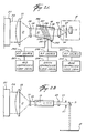
- Optical system 21 includes two cylindrical, anamorphic lenses 22, 23 which compress the monochromatic light from beam 12 into a narrow set of parallel rays 24 which are introduced into Bragg cell 31, or other suitable acoustic-optical light modulating device.
- Bragg cell 31 uses an anisotropic acoustic-optical crystal 32 and has a transducer 42 mounted on a side non colinear to the path of beam 24.
- a wave absorber 44 is mounted on another side of anisotropic crystal 32 facing the side of anisotropic crystal 32 upon which transducer 42 is mounted, with acoustic waves 43 propagated between transducer 42 and absorber 44.
- Acoustic waves 43 are generated by transducer 42 and respond to signals from a radio frequency source 45 connected to transducer 42 by cable 47.
- Radio frequency source 45 is driven by a data compression system 53 connected by cable 55 to RF source 45 with cable 57 connecting compressor 53 and video signal receiver 51.
- the video compressor 53 serves to decrease the time required for sound waves 43 which correspond to a video line, to enter fully into the Bragg cell 31.
- the modulated output beam 61 is transmitted to cylindrical anamorphic lense 63 which is used for output projection.
- Lense 63 focuses the modulated light beam into a beam 65 which is projected onto optical slit 67.
- Optical slit 67 is positioned to block undiffracted light 64 exiting from the Bragg cell 31.
- the light beam 69 emitting from slit 67 is projected on a frame scanning mirror 71, such as a frame scanning galvanometer, and is thence positioned appropriately on a projection screen 81.
- beam 64 includes the undiffracted light exiting from crystal 32. This beam 64 is blocked by the optical slit 67 which keeps undiffracted light from reaching the projection screen 81. This is indicated by the lower dashed lines in Figure 1.
- the dashed lines in Figure 1, representing beam 65, indicate diffracted rays which are reflected by the mirror 71, such as a vibrating galvanometer, to the projection screen 81 at the particular line position which corresponds to the ordinal position of the corresponding line of video data of the original video signal received by the video signal receiver 51.
- the light modulation system or Bragg cell 31 uses anisotropic Bragg diffraction by shear waves travelling in a paratellurite crystal such as tellurium oxide (TeO2) as a principle of modulation.
- a paratellurite crystal such as tellurium oxide (TeO2)
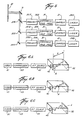
- the dot clock 100 is set to a frequency which represents the pixels along the compressed horizontal scan line.
- a scan line in an NTSC format is equal to approximately 63.5 micro-seconds, which includes approximately 10 micro-seconds for sync and blanking interval.
- each pixel will have an update rate of approximately 100 nano-seconds.
- the dot clock signal 100 is divided by the compression value "S", which is, for purposes of this example, equal to two, by divider 102 and produces a signal 104.
- Signal 104 is used as a clock for the "N only” generator 106.
- the other input for the "N only” generator 106 is the horizontal sync input 108. Every time a horizontal sync 108 arrives, the "N only” generator 106 will produce a series of N pulses 110. For a system as described above having 512 pixels per horizontal line, N would preferably be 512, with each pulse being approximately 100 nano-seconds long.
- the N pulses 110 are used to clock the input video RAM address counter 112.
- Address counter 112 supplies the address codes 119 needed to address the random access memories 114, 116 described below.
- the input video is being sampled and the data is being loaded into one of the RAM arrays 114, 116, the other RAM array 116, 114 is being read out at a compressed rate represented by pulses 118 originating from a second "N only" generator 120.
- "N only" generator 120 is driven by dot clock 100 as well but has no divider. Therefore it will run at the higher clock rate needed for compression.
- (H - CH) is the delay time for delay circuit 122.
- the delay time would be approximately equal to 31.5 micro-seconds.
- delay described here is prior to filling the crystal. Alternately, the crystal could be filled immediately and then the delay taken.
- the "N only" generator 120 produces 512 compressed rate pulses 118 at a rate of 50 nano-seconds.
- Signal 118 is used to clock the output compressed video RAM address counter 124 which supplies the necessary code 121 to change the address of either of the RAM arrays 114, 116 for output.
- the output data 126 is set to the RF source 45.
- Multiplexers 128, 130 and control flip flop 132 control the sequence of the use of the RAM arrays 114, 116.
- the control flip flop 132 determines which input signals are to be supplied to the RAM array 114, 116. For example, in the first cycle, RAM array 114 may read at the compressed rate through output data bus 126, while RAM array 116 writes at the video rate from the video signal 134. The cycle is triggered or changed by horizontal sync pulse 108. When the next sync pulse 108 arrives, the control signals 136, 138 from flip flop 132 to multiplexers 128, 130, respectively, switch and cause the RAM arrays 114, 116, respectively to reverse roles.
- the length of the crystal 32 measured from the acoustic transducer 42 to the wave absorber 44, is set to be equal to the distance the acoustic wave 43 must propagate to accommodate one horizontal scan line, divided by the compression ratio "S".
- the standard NTSC horizontal scan line "H" is equal to approximately 63.5 micro-seconds including blanking which takes about 10 micro-seconds, as discussed above.
- the acoustic wave 43 in anisotropic crystal 32, one should remember that because the output of the radio frequency generator 45 is amplitude modulated by the compressed video signal system 53, the acoustic waves to crystal 32 are also amplitude modulated.
- the laser beam shaping optics 21 are used to compress the laser beam into narrow parallel rays suitable to the size of a crystal 32.
- the incident pulsed beam 24 is diffracted by the acoustic wave 43 which propagates through crystal 32.
- Figure 6A there is illustrated one of the horizontal video scan line signals within Bragg cell 31.
- a horizontal line designated by the designator "A" is impressed across length "X" of crystal 32.
- "A” represents the time the video horizontal sync (modulated acoustic wave) first enters the Bragg cell 31.
- the signal (shown exaggerated for clarity) is propagating from the front left to the back right of Figure 6A.
- Figure 6B shows the acoustic wave after it has propagated approximately one-half way through crystal 32.
- the modulated acoustic wave for a single horizontal line has propagated through the crystal 32.
- the system is in a blanking mode. No light will illuminate the modulated wave 43 in the crystal 32.
- the information contained in one horizontal scan line is compressed, by compressor 53, to the appropriate size to fit within length "X" (Fig. 6A) of crystal 32.
- the propagation time is equal to H/S.
- the laser 11 is pulsed for a time not longer than the pixel time which is (H/S) ⁇ N, where H is one horizontal line time, "S” is a compression ratio and "N” equals the number of pixels. It should be noted that if the light pulse is longer than the required time set out above, then the acoustic waves would be observed in motion which would blur the image.
- the objective is to, in effect, stop the motion of the acoustic wave after there has been enough time for the information of one horizontal scan line to have propagated into the crystal 32. This effect is achieved by strobing or pulsing the light source 11.
- the acoustic-optical crystal 32 is made, preferably, of tellurium oxide TeO2.
- the usual sound velocity of tellurium oxide is 4.22 x 105 cm/sec.
- acoustic attenuation is minimized. Also, because of the shear waves, a high resolution can be obtained within a much smaller crystal than the same resolution in an elogated crystal such as the prior art of Yamamoto.
- the acoustic radio frequency is also lower in the shear mode as discussed above, of, for example, fifty megahertz. The same resolutions for an elongated crystal would require an acoustic wave frequency about twice as much or approximately one hundred megahertz which would contribute significantly to acoustic attenuation.
- a several color projector such as three colors, is shown in Figure 2.
- Laser light in beam 212 is caused by lasers 211 to incide on crystal 32.
- Optic system 21 narrows the beam through a series of lenses 22, 23, as discussed above, so that a narrow beam 24 incides on crystal 32 of Bragg cell 31.
- a series of transducers 240, 241, 242 are driven by a series of RF sources 245, 246, 247, respectively with transducers 240, 241, 242 adhered to crystal 32.
- RF sources 245, 246, 247 are modulated one horizontal line at a time by compressed video signals for compression systems 253, 254, 255, respectively.
- the width of the light pulse is less than or equal to a pixel of time.
- the configuration of Figure 2 allows the modulation of more than one light beam, each of the light beams being monochromatic and each usually of a different wave length from the others, in a single modulator of Bragg cell 31.
- a multi-color picture can be displayed if the light beam colors are, for example, three diverse wave lengths, such as wave lengths W1, W2, W3 representing the red, green, and blue primaries.
- the three radio frequency sources, 245, 246, 247 must simultaneously cause the three acoustic waves 256, 257, 258, respectively, to exist simultaneously in crystal 32 for modulating each horizontal line.
- the acoustic waves 256, 257, 258 are presumed to be constant-frequency, amplitude-modulated signals, having wave lengths T1, T2, T3 respectively.
- the modulation of the video signals corresponding to radio frequency sources 245, 246, 247 is supplied by the video signal compression systems 253, 254, 255, respectively, after being received from, for example, the air waves or cable by the video system 51.
- a laser family which meets the needs necessary to obtain the high energy to light efficiency, average power and the appropriate red, green and blue lines to produce a multi-color display, and which is accordingly preferable, is the metal vapor family.
- the neutral atoms are excited to the first residence level by electron impact. Although these levels are strongly coupled to the ground state, radiation trapping at densities above about 1012/CM3 increases the upper state lifetime. Laser action occurs between levels which are metastable. Build-up of atoms in the lower levels (both by stimulated emission and by direct electron pumping) causes the inversion to cease. After the return of the metastable atoms to the ground state, the laser may be pulsed again. With neon as a buffer gas and appropriate pressure and field strengths, deactivation times are estimated to be less than 25 micro-seconds. Because of the short deactivation times, the laser may be pulsed at high "rep" rates, such as greater than 30,000 Hertz.
- the required "rep" rate of approximately 15,750 Hertz is easily obtained.
- the pulse width is approximately 30 to 40 nano-seconds.
- Another important feature of the metal vapor family of lasers is the energy to light efficiency. This efficiency is at least as good as Nd:Yag lasers and may be better.
- the overall output efficiency is undiminished by any need for using wave length conversion optics such as dye cells.
- the metal vapor laser is capable of very high average power. Fifty watts in single bores and higher, greater than one hundred watts in an amplifier condition, may be achieved.
- NTSC green is centered approximately at .540 microns.
- Green light of approximately .510 microns may be produced by using waste heat from the gas discharge which provides the power necessary to vaporize copper present within the plasma tube.
- .578 microns yellow light is produced which can be used for a limiting dichroic display or increased luminance.
- metals that may be suitable to provide the necessary green color besides copper could be manganese which has a wave length of approximately .534 microns, lead which has a wave length of approximately .537 microns and iron which has a wave length of approximately .540 microns. It should be noted that not all of these may lase at high average powers. However, the lower average powers may be used for smaller displays that may be under a total projection luminosity of, for example, one thousand lumens. Because of the technical advances of copper vapor lasers, they will be acceptable for producing the green although any of the other metals could be used.
- red being centered at approximately .610 microns
- a laser type similar to that described above for the green laser is acceptable but using gold as the vaporized medium.
- Other metals besides gold that could be used would be calcium which produces wave lengths of approximately .610 microns, .612 microns and .616 microns.
- gold at .628 microns is preferable for providing a better color gamut.
- the metal vapor lasers used could be similar to those for copper and gold except bismuth could possibly be developed as a suitable vaporizing medium.
- Other possible alternatives would be cadmium which has a wave length of approximately .488 microns, beryllium which has a wave length of approximately .467 microns, cesium which has a wave length of approximately .455 microns, iron which has a wave length of approximately .452 microns and indium which has a wave length of approximately .451 microns.
- cesium iron and indium appear to be low in the luminosity efficiency.
- no metal vapor pulsed laser capable of producing the same output wattage levels as the red and green metal vapor lasers has been developed.
- continuous wave lasers can be used in combination with the preferred red and green metal vapor lasers to comprise a multicolor system of acceptable wattage output of all colors.
- a continuous wave laser of one color used in a continuous mode with a polygonal rotating mirror may be used, in combination with metal vapor lasers of other colors, to produce a multicolor output.
- a single laser 311 is provided.
- Laser 311 would preferably be a metal vapor laser which has a vaporizing metal of, for example, copper having simultaneous differing wave length emissions, such as, for example, .510 microns and .578 microns for the copper.
- the wave lengths are separated by a dichroic beam splitter 313 which transmits one wave length, such as, for example, .578 microns and reflects the other wave length, such as .510 microns.
- the first wave length 315 which is transmitted by beam splitter 313 is further reflected by a mirror 317 into a beam 319 parallel to beam 321 reflected by beam splitter 313. Beams 319, 321 are processed in parallel.
- Bragg cells 31 are modulated, as discussed above, by a compressed or noncompressed video signal to modulate the light beams 319, 321, said signal passing through each Bragg cell 31, respectively, one horizontal line at a time.
- Projection optics 327, 329 are comprised of lenses 63 and optical slits 67.
- the resulting beam 331 is reflected by a reflector 333 to a second dichroic beam splitter 335 where it is combined with the beam 337 from projector 327 through dichroic beam splitter 335.
- the combined beam 339 is reflected by frame scanning mirror 71 and projected onto screen 81.
- Laser 341, for example could be a metal vapor laser which has a vaporizing metal of copper with a wave length of approximately .510 microns.
- Laser 343 could, for example, be a metal vapor laser which vaporizes gold and has a wave length of approximately .628 microns. Both beams would be used as the primaries of a dichroic display.
- Beams 319, 321 would be passed through shapers 21 and Bragg cells 31 as discussed above and projectors 327, 329, respectively, to be combined by reflector 333, and dichroic beam splitter 335 to impinge on frame scanning mirror 71 and thus be reflected onto projection surface 81.
- Laser 349 may be a metal vapor laser which has a vaporizing metal of copper with a wave length of approximately .510 microns.
- Laser 347 may be a metal vapor laser which vaporizes gold and has a wave length of approximately .628 microns.
- Laser 345 may be a metal vapor laser which vaporizes bismuth and has a wave length of approximately .472 microns.
- the operation of this system is substantially similar to the operation of the system of Figure 4.
- the beams from each laser 345, 347, 349 are shaped by shaper optics 21 and modulated by Bragg cells 31.
- the combined beam is reflected by frame scanning mirror 71 and is projected on the projection surface 81.
- frame scanning mirror 71 may be either a rotating polygonal mirror or be driven by a galvanometer. Either would be synchronized to the vertical field pulse of the video signal which would cause a scan line picture to be offset slightly on the projection surface 81 to produce the picture.
- laser light beam 12 emitted by laser 11 incides on acoustic-optical crystal 32.
- the inciding rays 24 form a narrow beam.
- rays 24 Prior to inciding on crystal 32, rays 24 are divided by a beam splitter 26 to form a beam 24' which is parallel to beam 24.
- a mirror 27 is used to cause beam 24' to incide onto crystal 32 of Bragg cell 31.
- a set of transducers 42, 42' are mounted at different positions on the same side of crystal 32, with acoustic waves 43, 43', respectively, introduced between transducers 42, 42' and absorber 44.
- the acoustic signals 43, 43' are generated by transducers 42, 42' in response to signals from radio frequency sources 45, 45' connected by cables 47, 47', respectively.
- Radio frequency sources 45, 45' are modulated, two horizontal lines at a time, by compressed video signals from compression systems 53, 53', respectively.
- a video collator 91 supplies the compression systems 53, 53' with one horizontal line signal 92 and the next horizontal line signal 93, respectively.
- the input signal 51 is sampled by the video collator 91 one horizontal line at a time. For example, when the first line is sampled, it is stored by the video collator 91 until the next line is sampled.
- the video collator sends signals 92, 93, which represent two lines of complete video at the same time. Accordingly, signals 92, 93 cause acoustic waves 43, 43' to propagate across crystal 32 simultaneously to absorber 44, while laser 11 provides a light pulse 12 when the full horizontal lines have propagated completely into crystal 32. As in the previous embodiments, the width of the light pulse is less than or equal to a pixel of time. Accordingly, two modulated output beams 61, 61' exit from crystal 32 to cylindrical lenses 54, 56, respectively. Lenses 54, 56 serve to focus the output beams 61, 61' for display on projection surface 81.
- the focused light beams 61, 61' exit lenses 54, 56, respectively, and are transmitted to cylindrical lense 58.
- Lense 58 is used to further focus the light beam set 61, 61' prior to introduction to lense 63.
- the output from lense 58 is then transmitted to cylindrical lense 63 which is used for output projection.
- Lense 63 focuses the modulated light beams into light beams 65, 65' which are projected onto optical slit 67.
- optical slit 67 is positioned to block undiffracted light 64 exiting from the Bragg cell 31.
- the light beam set 69, 69' emitting from slit 67 is projected on a frame scanning mirror 71.
- Frame scanning mirror 71 positions the light signal appropriately onto projection surface or screen 81. For this purpose, after frame scanning mirror 71 reflects signals 69, 69', these signals are transmitted to cylindrical lense 100 which is used to adjust the distance between the parallel output beam set 69, 69' when projected onto projection surface 81.
- the video signals 92, 93 may also be supplied by a parallel source, such as a separate video source for each signal respectively, instead of using the video collator 91. This would be used for parallel input. It should also be noted that the multi-line writing is not limited to two lines as described above. This description serves as an illustrative purpose. Any reasonable number of lines could be used, such as three or more.
- the multi-line writing allows an increase in the vertical resolution of the projection without increasing band width of the incoming video. For example, if double line writing were used, and the requested output resolution was limited to 525 lines, on NTSC standard, then the light source would only have to pulse once for every two horizontal lines, which would be approximately 8000 Hz. Accordingly, because the laser source 11 would only be required to pulse half as much time, as discussed supra , the operational life of the laser source 11 would be substantially longer.
- the output vertical resolution could exceed 1500 lines.
- the input signal scan lines could be from parallel sources rather than a single source.
- the average laser power can also be increased because a lower repetition rate generally increases laser energy to light efficiency.
- the source for any color could consist of more than one laser having substantially the same, or similar, frequency. They are not to be considered exhaustive.
Landscapes
- Physics & Mathematics (AREA)
- Nonlinear Science (AREA)
- General Physics & Mathematics (AREA)
- Optics & Photonics (AREA)
- Engineering & Computer Science (AREA)
- Multimedia (AREA)
- Signal Processing (AREA)
- Video Image Reproduction Devices For Color Tv Systems (AREA)
- Transforming Light Signals Into Electric Signals (AREA)
- Endoscopes (AREA)
- Testing, Inspecting, Measuring Of Stereoscopic Televisions And Televisions (AREA)
- Television Systems (AREA)
- Control Of Indicators Other Than Cathode Ray Tubes (AREA)
Claims (15)
- Ein Videobilderzeugungssystem, das auf elektrische Signale anspricht, die ein Bild darstellen, mit einer Lichtquelle für wenigstens eine ausgewählte Frequenz, die wenigstens einen gepulsten Laser (11) aufweist, einer akusto-optischen Zelle (31) mit einem Medium zur Schallübertragung mit einer ersten Fläche, die dem Laser gegenüberliegt, und einem Wandler (42) zum Umwandeln eines elektrischen Signales in eine Schallwelle, der an einer Fläche mit Ausnahme der ersten Fläche befestigt ist, um Schallwellen (43) zu erzeugen, die nicht-colinear mit dem Licht von dem Laser sind, jedoch auf dieses einwirken; einer Signaleinrichtung (45, 51, 53) zum Treiben des Wandlers, um amplitudenmodulierte Schallwellen zu erzeugen, welche den elektrischen Signalen für eine Zeile des Bildes entsprechen; einer Projektionsfläche (81); und einer sequentiellen ebenen Projektionseinrichtung (63, 71), die bewirkt, daß das Licht von dem Medium auf die Projektionsfläche bei einer speziellen Zeilenposition auftrifft, die der Ordnungsposition der entsprechenden Zeile der Videodate innerhalb des Bildes entspricht, dadurch gekennzeichnet, daß die Signaleinrichtung eine Kompressionseinrichtung (53) zum elektronischen Reduzieren der Zeitdauer für ein Signal, welches die Zeile des Bildes darstellt, umfaßt, wobei die Kompressionseinrichtung eine erste Einrichtung (114, 116) zum Speichern von Daten bei einer Echtzeitrate der elektrischen Signale und eine zweite Einrichtung (120, 128, 130, 132), die eine Zufuhr der Daten von der ersten Einrichtung zu dem Wandler (42) mit einer höheren Rate als die Echtzeitrate der elektrischen Signale veranlaßt, umfaßt.
- Ein System nach Anspruch 1, dadurch gekennzeichnet, daß der Laser (11) ein gepulster Metalldampflaser ist.
- Ein System nach Anspruch 1 oder 2, dadurch gekennzeichnet,daß eine einzige akusto-optische Zelle mit einer Mehrzahl von Wandlern (240, 241, 242) zur Umwandlung elektrischer Signale in Schallwellen, welche auf der einzigen Zelle befestigt sind, verwendet wird.
- Ein System nach einem der vorhergehenden Ansprüche, dadurch gekennzeichnet, daß die Lichtquelle drei getrennte, gepulste Laser (211) umfaßt, um monochromatische rote, grüne und blaue Lichtstrahlen zu der akusto-optischen Zelle (31) zuzuführen, um ein Vielfarb-Videobilderzeugungssystem zu schaffen.
- Ein System nach einem der vorhergehenden Ansprüche, dadurch gekennzeichnet, daß die akusto-optische Zelle (31) ein anisotrophes Medium umfaßt.
- Ein System nach Anspruch 1 oder 2, dadurch gekennzeichnet, daß die Lichtquelle eine Mehrzahl von gepulsten Lasern (211) umfaßt, wobei die Laser unterschiedliche monochromatische Farben emittieren, und daß ferner eine Mehrzahl von Schallwellenwandlern (240, 241, 242) vorgesehen sind, von denen ein jeder einem der Laser entspricht und ausgerichtet ist, daß jede der monochromatischen Farben von den Lichtquellen durch die Schallwellen von einem der Wandler moduliert wird, wobei die Signaleinrichtung ferner eine Mehrzahl von Signalquellen (245, 246, 247) umfaßt, wobei jede der Quellen den elektrischen Signalen für die Farbe eines jeweiligen Lasers für die Zeile des Bildes entspricht.
- Ein System nach Anspruch 6, dadurch gekennzeichnet, daß ferner eine Einrichtung zum Mischen der modulierten Farbsignale vorgesehen ist.
- Ein System nach Anspruch 2, dadurch gekennzeichnet, daß ferner eine Mehrzahl von Zellen (31) vorgesehen sind, wobei an jede der Zellen einer der Wandler angebracht ist.
- Ein System nach einem der vorhergehenden Ansprüche, dadurch gekennzeichnet, daß die erste Einrichtung der Kompressionseinrichtung (53) einen ersten und einen zweiten Speicher (114, 116) mit wahlfreiem Zugriff umfaßt, die unter der Steuerung von Multiplexern (128, 130) und eines Steuer-Flip-Flop (132) wahlweise Eingangsvideodaten (134) bei der Echtzeitrate empfangen, die durch den ersten Pulsgenerator (106) festgelegt ist, oder die Daten zu dem Wandler (42) mit einer höheren Rate zuführen, welche durch einen zweiten Pulsgenerator (120) festgelegt ist, wobei die Anordnung derart vorgesehen ist, daß einer der Speicher mit wahlfreiem Zugriff Daten (134) empfängt, während der andere Speicher mit wahlfreiem Zugriff Daten zu den Wandlern zuführt.
- Ein Verfahren zum Anzeigen von Videobildern entsprechend einem elektrischen Signal, welches die Bilder auf einer Projektionsfläche (81) darstellt, mit folgenden Verfahrensschritten: Empfangen des Signales; Umwandeln einer jeden Zeile des Signales in Schallwellen; Einführen der Schallwellen in ein Medium (32) zum Übertragen der Schallwellen; Warten, bis genug Schallwellen zur Darstellung einer vollen Zeile eines Bildes in dem Medium enthalten sind; Einführen wenigstens eines Pulses von monochromatischem Licht in das Medium nach dem Warteschritt über eine Zeitdauer, die geringer ist als die Ausbreitung eines Pixels in dem Medium und bei einem Winkel, der bewirkt, daß das monochromatische Licht durch die Schallwelle läuft, wodurch das monochromatische Licht moduliert wird; Fokussieren des modulierten Lichtes; und Belichten des Abschnittes der Projektionsfläche, welcher der Zeile entspricht, mit der modulierten Zeile des monochromatischen Lichtes, dadurch gekennzeichnet, daß nach dem Empfangen des Signales und vor dem Umwandeln des Signales in Schallwellen das Signal elektrisch komprimiert wird, um die Zeitdauer eines Signales, welches eine Bildzeile darstellt, zu vermindern, wobei die Kompression erstens die Speicherung von Daten bei der Echtzeitrate der elektrischen Signale und zweitens die Übertragung der Daten von dem Speicher zu dem Wandler mit einer höheren Rate als der Echtzeitrate der elektrischen Signale umfaßt.
- Ein Verfahren nach Anspruch 10, dadurch gekennzeichnet, daß getrennte Pulse von rotem, grünem und blauem monochromatischen Licht von gepulsten Lasern (211) in das Medium (32) eingebracht werden, um ein vielfarbiges Videobild zu erzeugen.
- Ein Verfahren nach Anspruch 10 oder 11, dadurch gekennzeichnet, daß eine einzige Zelle (31) des Mediums für die Übertragung der Schallwellen vorgesehen ist; daß eine Mehrzahl von getrennten monochromatischen Lichtstrahlen in die Zelle eingebracht werden; und daß jeder der Lichtstrahlen moduliert wird, um eine modulierte, vielfarbige Anzeige auf der Projektionsfläche (81) zu schaffen.
- Ein Verfahren nach einem der Ansprüche 10 bis 12, dadurch gekennzeichnet, daß das Medium (32) anisotrophes Material umfaßt und daß die Lichtpulse durch einen oder mehrere gepulste Metalldampflaser erzeugt werden.
- Ein Verfahren nach einem der Ansprüche 10 bis 13, dadurch gekennzeichnet, daß das Signal elektronisch komprimiert wird, indem dieses in einen ersten und in einen zweiten Speicher (114, 116) bei der Echtzeitrate eingespeichert wird und indem dieses zur Umwandlung in Schallwellen mit einer höheren Rate zugeführt wird, wobei die Anordnung derart ist, daß das Signal von einem der Speicher empfangen wird, während der andere Speicher seinen vorher abgespeicherten Inhalt zur Umwandlung in Schallwellen zuführt.
- Ein Verfahren zum Anzeigen von Videobildern nach Anspruch 10, mit folgenden Schritten: Elektronisches Komprimieren von wenigstens zwei Zeilen des Signales, im wesentlichen gleichzeitiges Einbringen einer jeden Zeile von Schallwellen in das Medium (32); Einbringen eines Pulses (24, 24') von monochromatischem Licht in das Medium für jede der Zeilen; Fokussieren jeder modulierten Zeile des monochromatischen Lichtes; und Belichten des Abschnittes des Schirmes, welcher einer jeden Zeile entspricht, mit der entsprechenden modulierten Zeile des monochromatischen Lichtes.
Priority Applications (2)
| Application Number | Priority Date | Filing Date | Title |
|---|---|---|---|
| AT88300373T ATE92198T1 (de) | 1984-04-26 | 1988-01-18 | Video-abbildungssysteme. |
| DE88300373T DE3882691T2 (de) | 1984-04-26 | 1988-01-18 | Video-abbildungssysteme. |
Applications Claiming Priority (2)
| Application Number | Priority Date | Filing Date | Title |
|---|---|---|---|
| US06/604,308 US4720747A (en) | 1984-04-26 | 1984-04-26 | Sequential plane projection by laser video projector |
| CA000556647A CA1330588C (en) | 1984-04-26 | 1988-01-15 | Sequential plane projection by laser video projector |
Publications (2)
| Publication Number | Publication Date |
|---|---|
| EP0325008A1 EP0325008A1 (de) | 1989-07-26 |
| EP0325008B1 true EP0325008B1 (de) | 1993-07-28 |
Family
ID=25671665
Family Applications (1)
| Application Number | Title | Priority Date | Filing Date |
|---|---|---|---|
| EP88300373A Expired - Lifetime EP0325008B1 (de) | 1984-04-26 | 1988-01-18 | Video-Abbildungssysteme |
Country Status (5)
| Country | Link |
|---|---|
| US (1) | US4720747A (de) |
| EP (1) | EP0325008B1 (de) |
| AT (1) | ATE92198T1 (de) |
| AU (1) | AU613889B2 (de) |
| DE (1) | DE3882691T2 (de) |
Families Citing this family (41)
| Publication number | Priority date | Publication date | Assignee | Title |
|---|---|---|---|---|
| US4851918A (en) * | 1984-04-26 | 1989-07-25 | Corporation For Laser Optic Research | Sequential plane projection by laser video projector |
| JPS62237862A (ja) * | 1986-04-09 | 1987-10-17 | Kowa Co | レ−ザ−光走査装置 |
| JPH0614662B2 (ja) * | 1986-04-09 | 1994-02-23 | 興和株式会社 | レーザー走査型画像入力装置 |
| US4951150A (en) * | 1989-03-01 | 1990-08-21 | Foresight, Inc. | Optical projection system |
| JPH0385589A (ja) * | 1989-08-30 | 1991-04-10 | Pioneer Electron Corp | プロジェクションディスプレイ装置 |
| WO1991004632A1 (en) * | 1989-09-12 | 1991-04-04 | Foresight, Inc. | Optical projection system with electronic sector erase system |
| US6008925A (en) * | 1991-06-07 | 1999-12-28 | Advanced Laser Technologies, Inc. | Light beam scanning apparatus and method |
| KR0125452B1 (ko) * | 1991-11-20 | 1997-12-19 | 순페이 야마자끼 | 화상표시방법 및 화상표시장치 |
| US5253073A (en) * | 1992-04-01 | 1993-10-12 | Corporation For Laser Optics Research | Electronic data multiplexing in a full color pulsed laser projector and method |
| US5317348A (en) * | 1992-12-01 | 1994-05-31 | Knize Randall J | Full color solid state laser projector system |
| CN1119482A (zh) * | 1993-02-03 | 1996-03-27 | 尼托公司 | 图像投影的方法和设备 |
| US5311321A (en) * | 1993-04-22 | 1994-05-10 | Corporation For Laser Optics Research | Laser video imaging system with pulse backtrack and method |
| US5410371A (en) * | 1993-06-07 | 1995-04-25 | The United States Of America As Represented By The Administrator Of The National Aeronautics And Space Administration | Display system employing acoustro-optic tunable filter |
| US5534950A (en) * | 1993-10-04 | 1996-07-09 | Laser Power Corporation | High resolution image projection system and method employing lasers |
| US5990983A (en) * | 1994-09-30 | 1999-11-23 | Laser Power Corporation | High resolution image projection system and method employing lasers |
| US5774174A (en) * | 1996-02-07 | 1998-06-30 | Hardie; Robert Joseph | Laser projector |
| US5740190A (en) * | 1996-05-23 | 1998-04-14 | Schwartz Electro-Optics, Inc. | Three-color coherent light system |
| US6154259A (en) * | 1996-11-27 | 2000-11-28 | Photera Technologies, Inc. | Multi-beam laser scanning display system with speckle elimination |
| AU723050B2 (en) | 1997-01-28 | 2000-08-17 | Christie Digital Systems Usa, Inc. | Video projection holographic screen, system and method |
| AU722995B2 (en) | 1997-01-28 | 2000-08-17 | Christie Digital Systems Usa, Inc. | Laser video display system and method |
| DE19706920A1 (de) * | 1997-02-20 | 1998-09-03 | Fraunhofer Ges Forschung | Verfahren zum Projizieren eines Bilds auf einer Abbildungsfläche mittels einer Laseranordnung |
| KR100215298B1 (ko) * | 1997-07-03 | 1999-08-16 | 윤종용 | 소형의 집속 광학계를 구비한 대화면 레이저투사영상장치와 빔경로 확대장치 및 방법 |
| KR100300959B1 (ko) * | 1997-07-05 | 2001-10-26 | 윤종용 | 플랫플레이트를이용한광분리장치와광분리방법및광분리장치의제조방법 |
| KR100251052B1 (ko) * | 1997-07-12 | 2000-05-01 | 윤종용 | 두개의 플랫 플레이트 사이의 에어 갭 및 하이브리드 다이크로익 미러를 이용한 광분리 장치 및 방법 |
| US6005718A (en) * | 1997-07-14 | 1999-12-21 | Samsung Electronics Co., Ltd. | Apparatus and a method for combining light using one flat plate and a method for manufacturing the apparatus |
| KR100251053B1 (ko) * | 1997-07-25 | 2000-05-01 | 윤종용 | 2개의 평판을 이용한 광통합 장치 및 광통합 방법 |
| US6317170B1 (en) | 1997-09-13 | 2001-11-13 | Samsung Electronics Co., Ltd. | Large screen compact image projection apparatus using a hybrid video laser color mixer |
| JP3551058B2 (ja) * | 1999-01-21 | 2004-08-04 | 株式会社日立製作所 | 投写型画像ディスプレイ装置 |
| US6188507B1 (en) * | 1999-03-17 | 2001-02-13 | Mission Research Corporation | Variable acousto-optic spectrum projector and method of operation |
| US6426781B1 (en) * | 1999-03-26 | 2002-07-30 | Samsung Electronics Co., Ltd. | Laser video projector |
| US7102700B1 (en) * | 2000-09-02 | 2006-09-05 | Magic Lantern Llc | Laser projection system |
| US6711187B2 (en) | 2002-04-22 | 2004-03-23 | Evans & Sutherland Computer Corporation | Rapidly oscillating laser light source |
| WO2004109872A1 (en) * | 2003-06-03 | 2004-12-16 | Corporation For Laser Optics Research | Laser video projection system and method with anti-piracy feature |
| US7244028B2 (en) * | 2004-12-14 | 2007-07-17 | Coherent, Inc. | Laser illuminated projection displays |
| US7355657B2 (en) * | 2004-12-14 | 2008-04-08 | Coherent, Inc. | Laser illuminated projection displays |
| US7413311B2 (en) * | 2005-09-29 | 2008-08-19 | Coherent, Inc. | Speckle reduction in laser illuminated projection displays having a one-dimensional spatial light modulator |
| CN101617354A (zh) | 2006-12-12 | 2009-12-30 | 埃文斯和萨瑟兰计算机公司 | 用于校准单个调制器投影仪中的rgb光的系统和方法 |
| US8358317B2 (en) | 2008-05-23 | 2013-01-22 | Evans & Sutherland Computer Corporation | System and method for displaying a planar image on a curved surface |
| US8702248B1 (en) | 2008-06-11 | 2014-04-22 | Evans & Sutherland Computer Corporation | Projection method for reducing interpixel gaps on a viewing surface |
| US8077378B1 (en) | 2008-11-12 | 2011-12-13 | Evans & Sutherland Computer Corporation | Calibration system and method for light modulation device |
| US9641826B1 (en) | 2011-10-06 | 2017-05-02 | Evans & Sutherland Computer Corporation | System and method for displaying distant 3-D stereo on a dome surface |
Family Cites Families (19)
| Publication number | Priority date | Publication date | Assignee | Title |
|---|---|---|---|---|
| US3462603A (en) * | 1966-05-02 | 1969-08-19 | Bell Telephone Labor Inc | Acoustic licht modulator and variable delay device |
| US3818129A (en) * | 1971-06-30 | 1974-06-18 | Hitachi Ltd | Laser imaging device |
| US3783185A (en) * | 1972-01-28 | 1974-01-01 | Eastman Kodak Co | Multi-color acoustooptic modulator |
| JPS5431816B2 (de) * | 1973-12-14 | 1979-10-09 | ||
| US4052121A (en) * | 1975-09-10 | 1977-10-04 | Itek Corporation | Noncollinear tunable acousto-optic filter |
| US4021845A (en) * | 1975-10-16 | 1977-05-03 | Xerox Corporation | Laser for generating white light |
| US4149183A (en) * | 1976-05-21 | 1979-04-10 | Xerox Corporation | Electronic halftone generator |
| US4348611A (en) * | 1978-03-02 | 1982-09-07 | Wolfgang Ruppel | Ferroelectric or pyroelectric sensor utilizing a sodium nitrite layer |
| US4295103A (en) * | 1978-03-23 | 1981-10-13 | Ariold Ljudmirsky | Metal vapor laser |
| US4213158A (en) * | 1978-06-28 | 1980-07-15 | Xerox Corporation | Optical data recording system utilizing acoustic pulse imaging to minimize image blur |
| US4295145A (en) * | 1978-12-29 | 1981-10-13 | International Business Machines Corporation | Acousto-optically modulated laser scanning arrangement for correcting for interference appearing therein |
| US4562461A (en) * | 1981-10-08 | 1985-12-31 | Yin Ronald L | Display apparatus and method therefor |
| US4414583A (en) * | 1981-11-02 | 1983-11-08 | International Business Machines Corporation | Scanned light beam imaging method and apparatus |
| JPS58132731A (ja) * | 1982-02-03 | 1983-08-08 | Hoya Corp | 2進光束偏向器 |
| GB8323316D0 (en) * | 1983-08-31 | 1983-10-05 | Prutec Ltd | Laser display system |
| US4540245A (en) * | 1983-11-10 | 1985-09-10 | Isomet Corporation | Apparatus and method for acousto-optic character generation |
| US4639073A (en) * | 1984-03-19 | 1987-01-27 | Xerox Corporation | Electro-optic pulse imaging raster output scanner |
| US4587565A (en) * | 1984-04-12 | 1986-05-06 | Ltv Aerospace And Defense Company | Pressure sensitive film display having multiple gray levels |
| US4639763A (en) * | 1985-04-30 | 1987-01-27 | Rca Corporation | Interlace to non-interlace scan converter for RGB format video input signals |
-
1984
- 1984-04-26 US US06/604,308 patent/US4720747A/en not_active Expired - Fee Related
-
1988
- 1988-01-14 AU AU10264/88A patent/AU613889B2/en not_active Ceased
- 1988-01-18 DE DE88300373T patent/DE3882691T2/de not_active Expired - Fee Related
- 1988-01-18 EP EP88300373A patent/EP0325008B1/de not_active Expired - Lifetime
- 1988-01-18 AT AT88300373T patent/ATE92198T1/de active
Non-Patent Citations (1)
| Title |
|---|
| "The Laser Guidebook" by J. Hecht, McGraw-Hill, NY, 1986, in particular chapter 12, pp. 163-177. * |
Also Published As
| Publication number | Publication date |
|---|---|
| EP0325008A1 (de) | 1989-07-26 |
| US4720747A (en) | 1988-01-19 |
| AU1026488A (en) | 1989-07-20 |
| AU613889B2 (en) | 1991-08-15 |
| ATE92198T1 (de) | 1993-08-15 |
| DE3882691T2 (de) | 1993-11-04 |
| DE3882691D1 (de) | 1993-09-02 |
Similar Documents
| Publication | Publication Date | Title |
|---|---|---|
| US4720747A (en) | Sequential plane projection by laser video projector | |
| US4851918A (en) | Sequential plane projection by laser video projector | |
| US6753931B2 (en) | Pulse sequencing for generating a color image in laser-based display systems | |
| US3818129A (en) | Laser imaging device | |
| US5253073A (en) | Electronic data multiplexing in a full color pulsed laser projector and method | |
| JP4853033B2 (ja) | 光走査装置及び画像表示装置 | |
| AU722995B2 (en) | Laser video display system and method | |
| US6426781B1 (en) | Laser video projector | |
| WO1998024240A1 (en) | Multi-beam laser scanning display system | |
| US20240428713A1 (en) | Display apparatus and method for displaying pixels of an image | |
| US5687020A (en) | Image projector using acousto-optic tunable filter | |
| JP2008250037A (ja) | 画像表示装置および表示制御装置 | |
| US7354157B2 (en) | Image display device and light source device | |
| EP0157791B1 (de) | Anzeigeanordnung | |
| JP5304839B2 (ja) | 光走査装置及び画像表示装置 | |
| US5097480A (en) | Acoustic modulation apparatus for laser | |
| US3639684A (en) | Field sequential laser scan for night color television | |
| CA1330588C (en) | Sequential plane projection by laser video projector | |
| US4009488A (en) | Video display system and method employing propagating stress waves | |
| JPH0552112B2 (de) | ||
| EP0398300B1 (de) | Licht-zu-Licht-Umsetzverfahren und Anzeigevorrichtung mit dessen Verwendung | |
| RU2116703C1 (ru) | Способ производства статических и динамических лазерных многоцветных изображений и лазерный проектор для его реализации | |
| JP2000250001A (ja) | 光学装置 | |
| Martinsen et al. | Pulsed RGB lasers for large-screen video displays | |
| KR100239223B1 (ko) | 입체 영상 구현 방법 및 이를 수행하기 위한 시스템 |
Legal Events
| Date | Code | Title | Description |
|---|---|---|---|
| PUAI | Public reference made under article 153(3) epc to a published international application that has entered the european phase |
Free format text: ORIGINAL CODE: 0009012 |
|
| AK | Designated contracting states |
Kind code of ref document: A1 Designated state(s): AT BE CH DE ES FR GB GR IT LI LU NL SE |
|
| RBV | Designated contracting states (corrected) |
Designated state(s): AT BE CH DE ES FR GB IT LI NL SE |
|
| 17P | Request for examination filed |
Effective date: 19900110 |
|
| 17Q | First examination report despatched |
Effective date: 19911111 |
|
| RAP3 | Party data changed (applicant data changed or rights of an application transferred) |
Owner name: CORPORATION FOR LASER OPTICS RESEARCH |
|
| GRAA | (expected) grant |
Free format text: ORIGINAL CODE: 0009210 |
|
| AK | Designated contracting states |
Kind code of ref document: B1 Designated state(s): AT BE CH DE ES FR GB IT LI NL SE |
|
| PG25 | Lapsed in a contracting state [announced via postgrant information from national office to epo] |
Ref country code: ES Free format text: THE PATENT HAS BEEN ANNULLED BY A DECISION OF A NATIONAL AUTHORITY Effective date: 19930728 Ref country code: AT Effective date: 19930728 Ref country code: SE Effective date: 19930728 Ref country code: IT Free format text: LAPSE BECAUSE OF FAILURE TO SUBMIT A TRANSLATION OF THE DESCRIPTION OR TO PAY THE FEE WITHIN THE PRE;WARNING: LAPSES OF ITALIAN PATENTS WITH EFFECTIVE DATE BEFORE 2007 MAY HAVE OCCURRED AT ANY TIME BEFORE 2007. THE CORRECT EFFECTIVE DATE MAY BE DIFFERENT FROM THE ONE RECORDED.SCRIBED TIME-LIMIT Effective date: 19930728 |
|
| REF | Corresponds to: |
Ref document number: 92198 Country of ref document: AT Date of ref document: 19930815 Kind code of ref document: T |
|
| REF | Corresponds to: |
Ref document number: 3882691 Country of ref document: DE Date of ref document: 19930902 |
|
| ET | Fr: translation filed | ||
| PLBE | No opposition filed within time limit |
Free format text: ORIGINAL CODE: 0009261 |
|
| STAA | Information on the status of an ep patent application or granted ep patent |
Free format text: STATUS: NO OPPOSITION FILED WITHIN TIME LIMIT |
|
| 26N | No opposition filed | ||
| REG | Reference to a national code |
Ref country code: CH Ref legal event code: PFA Free format text: CORPORATION FOR LASER OPTICS RESEARCH |
|
| PGFP | Annual fee paid to national office [announced via postgrant information from national office to epo] |
Ref country code: GB Payment date: 19990118 Year of fee payment: 12 |
|
| PGFP | Annual fee paid to national office [announced via postgrant information from national office to epo] |
Ref country code: DE Payment date: 19990129 Year of fee payment: 12 |
|
| PGFP | Annual fee paid to national office [announced via postgrant information from national office to epo] |
Ref country code: NL Payment date: 19990131 Year of fee payment: 12 |
|
| PGFP | Annual fee paid to national office [announced via postgrant information from national office to epo] |
Ref country code: BE Payment date: 19990201 Year of fee payment: 12 |
|
| PGFP | Annual fee paid to national office [announced via postgrant information from national office to epo] |
Ref country code: FR Payment date: 19990202 Year of fee payment: 12 |
|
| PGFP | Annual fee paid to national office [announced via postgrant information from national office to epo] |
Ref country code: CH Payment date: 19990204 Year of fee payment: 12 |
|
| PG25 | Lapsed in a contracting state [announced via postgrant information from national office to epo] |
Ref country code: GB Free format text: LAPSE BECAUSE OF NON-PAYMENT OF DUE FEES Effective date: 20000118 |
|
| PG25 | Lapsed in a contracting state [announced via postgrant information from national office to epo] |
Ref country code: CH Free format text: LAPSE BECAUSE OF NON-PAYMENT OF DUE FEES Effective date: 20000131 Ref country code: BE Free format text: LAPSE BECAUSE OF NON-PAYMENT OF DUE FEES Effective date: 20000131 Ref country code: LI Free format text: LAPSE BECAUSE OF NON-PAYMENT OF DUE FEES Effective date: 20000131 |
|
| BERE | Be: lapsed |
Owner name: CORPORATION FOR LASER OPTICS RESEARCH Effective date: 20000131 |
|
| PG25 | Lapsed in a contracting state [announced via postgrant information from national office to epo] |
Ref country code: NL Free format text: LAPSE BECAUSE OF NON-PAYMENT OF DUE FEES Effective date: 20000801 |
|
| GBPC | Gb: european patent ceased through non-payment of renewal fee |
Effective date: 20000118 |
|
| REG | Reference to a national code |
Ref country code: CH Ref legal event code: PL |
|
| PG25 | Lapsed in a contracting state [announced via postgrant information from national office to epo] |
Ref country code: FR Free format text: LAPSE BECAUSE OF NON-PAYMENT OF DUE FEES Effective date: 20000929 |
|
| NLV4 | Nl: lapsed or anulled due to non-payment of the annual fee |
Effective date: 20000801 |
|
| PG25 | Lapsed in a contracting state [announced via postgrant information from national office to epo] |
Ref country code: DE Free format text: LAPSE BECAUSE OF NON-PAYMENT OF DUE FEES Effective date: 20001101 |
|
| REG | Reference to a national code |
Ref country code: FR Ref legal event code: ST |