EP0325083A1 - Système pour produire de la vapeur d'eau à haute pression et à haute température - Google Patents
Système pour produire de la vapeur d'eau à haute pression et à haute température Download PDFInfo
- Publication number
- EP0325083A1 EP0325083A1 EP88500117A EP88500117A EP0325083A1 EP 0325083 A1 EP0325083 A1 EP 0325083A1 EP 88500117 A EP88500117 A EP 88500117A EP 88500117 A EP88500117 A EP 88500117A EP 0325083 A1 EP0325083 A1 EP 0325083A1
- Authority
- EP
- European Patent Office
- Prior art keywords
- vapour
- temperature
- boiler
- phase
- fuels
- Prior art date
- Legal status (The legal status is an assumption and is not a legal conclusion. Google has not performed a legal analysis and makes no representation as to the accuracy of the status listed.)
- Withdrawn
Links
- XLYOFNOQVPJJNP-UHFFFAOYSA-N water Substances O XLYOFNOQVPJJNP-UHFFFAOYSA-N 0.000 title claims abstract description 10
- 238000004519 manufacturing process Methods 0.000 title claims abstract description 6
- 239000000446 fuel Substances 0.000 claims abstract description 27
- 238000009434 installation Methods 0.000 claims abstract description 18
- 238000010438 heat treatment Methods 0.000 claims abstract description 13
- 238000003303 reheating Methods 0.000 claims abstract description 8
- 238000005260 corrosion Methods 0.000 claims abstract description 7
- 230000007797 corrosion Effects 0.000 claims abstract description 7
- 239000007788 liquid Substances 0.000 claims 1
- VNWKTOKETHGBQD-UHFFFAOYSA-N methane Chemical compound C VNWKTOKETHGBQD-UHFFFAOYSA-N 0.000 description 6
- 239000000567 combustion gas Substances 0.000 description 5
- 238000002485 combustion reaction Methods 0.000 description 4
- 239000007789 gas Substances 0.000 description 4
- 238000000034 method Methods 0.000 description 4
- 230000008569 process Effects 0.000 description 4
- 230000008901 benefit Effects 0.000 description 3
- 239000003245 coal Substances 0.000 description 3
- 238000010586 diagram Methods 0.000 description 3
- 230000006872 improvement Effects 0.000 description 3
- 239000003345 natural gas Substances 0.000 description 3
- 239000000295 fuel oil Substances 0.000 description 2
- 238000012423 maintenance Methods 0.000 description 2
- 230000009467 reduction Effects 0.000 description 2
- 229920006395 saturated elastomer Polymers 0.000 description 2
- 239000002028 Biomass Substances 0.000 description 1
- -1 derivates of petrol Substances 0.000 description 1
- 239000010791 domestic waste Substances 0.000 description 1
- 230000000694 effects Effects 0.000 description 1
- 239000002803 fossil fuel Substances 0.000 description 1
- 239000002440 industrial waste Substances 0.000 description 1
- 239000003921 oil Substances 0.000 description 1
- 239000000779 smoke Substances 0.000 description 1
- 230000005619 thermoelectricity Effects 0.000 description 1
- 238000009423 ventilation Methods 0.000 description 1
Images
Classifications
-
- F—MECHANICAL ENGINEERING; LIGHTING; HEATING; WEAPONS; BLASTING
- F22—STEAM GENERATION
- F22G—SUPERHEATING OF STEAM
- F22G1/00—Steam superheating characterised by heating method
- F22G1/16—Steam superheating characterised by heating method by using a separate heat source independent from heat supply of the steam boiler, e.g. by electricity, by auxiliary combustion of fuel oil
-
- F—MECHANICAL ENGINEERING; LIGHTING; HEATING; WEAPONS; BLASTING
- F22—STEAM GENERATION
- F22B—METHODS OF STEAM GENERATION; STEAM BOILERS
- F22B31/00—Modifications of boiler construction, or of tube systems, dependent on installation of combustion apparatus; Arrangements or dispositions of combustion apparatus
- F22B31/04—Heat supply by installation of two or more combustion apparatus, e.g. of separate combustion apparatus for the boiler and the superheater respectively
- F22B31/045—Steam generators specially adapted for burning refuse
-
- Y—GENERAL TAGGING OF NEW TECHNOLOGICAL DEVELOPMENTS; GENERAL TAGGING OF CROSS-SECTIONAL TECHNOLOGIES SPANNING OVER SEVERAL SECTIONS OF THE IPC; TECHNICAL SUBJECTS COVERED BY FORMER USPC CROSS-REFERENCE ART COLLECTIONS [XRACs] AND DIGESTS
- Y02—TECHNOLOGIES OR APPLICATIONS FOR MITIGATION OR ADAPTATION AGAINST CLIMATE CHANGE
- Y02E—REDUCTION OF GREENHOUSE GAS [GHG] EMISSIONS, RELATED TO ENERGY GENERATION, TRANSMISSION OR DISTRIBUTION
- Y02E20/00—Combustion technologies with mitigation potential
- Y02E20/12—Heat utilisation in combustion or incineration of waste
Definitions
- This invention refers to a system for the production of water vapour with high pressure and temperature levels, by means of which it is possible to overcome the pressure and temperature restrictions which exist with current designs of boilers whilst burning, whether totally or in the most part, problematic fuels.
- the aim of this invention is to develop a system for the production of water vapour with high pressure and temperature levels, whereby part of the heating process is carried out by the use of those fuels of the type known as problematic, eliminating the above mentioned problems which make it necessary to introduce restrictions with regard to the characteristics of the vapour obtained.
- the first phase of generating the vapour is by using a boiler fed exclusively or in the most part by low quality fuels and/or fuels where there is a serious problem of corrosion at high temperatures, these fuels being of the type called problematic above.
- a saturated or slightly superheated vapour is obtained, with pressure and temperature characteristics whereby the temperature restrictions aimed at avoiding problematic situation and an undesirable degree of corrosion of the elements of the boiler are not surpassed.
- the vapour produced has a higher pressure level than is usual in this type of installation whilst remaining compatible with the boiler.
- the superheating unit whilst generating the saturated or slightly superheated vapour, the superheating unit is either omitted or the temperature within this is notably lower than that of conventional installations, by warrant of which the operative problems mentioned above are overcome.
- the characteristics of the vapour produced are such that they allow for qualitative improvements for it to be used in the generation of electric power, or for uses where it is necessary for the vapour to have pressure and/or temperature levels which are higher than those normally generated in boilers burning those fuels known as problematic.
- the qualitative improvement of the vapour obtained during the first phase of the heating process is achieved during a second heating phase or process in which the temperature is increased to the desired level, for which a separate superheating-reheating installation is used, this being fed by traditional fuels, the use of which means that the necessary temperature of the vapour can be achieved.
- the two phases indicated are carried out by means of installations or boilers which are adequate for the type of fuel which being used.
- the second phase it is possible to superheat and, if need be, reheat the vapour, as many times as is necessary for the thermal cycle of the plant for which the vapour is destined.
- a non-problematic fuel will be used, for example natural gas (or combustion gases originating in another installation), fuel oil, coal, etc.
- the burner and/or grills, bundles of superheating and reheating units, etc. will be very flexible during this second phase to enable them to be adjusted in each case to the most appropriate technical and financial solution.
- the combustive air used in the separate superheating-reheating installation Before the combustive air used in the separate superheating-reheating installation enters the combustion chamber, it can be heated in a heat-exchange unit, taking advantage of some thermal power of the hot smoke, before being evacuated through the chimney.
- a recirculation process can be made available for the gases in order to regulate the temperature of these within the installation, and this process can vary depending on the installation used to make it compatible to its design and mode of operation.
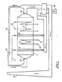
- the attached diagram shows a vapour superheating-reheating installation used for carrying out the second phase of the process.
- reference no. 1 indicates a heating unit provided with a series of burners (2), fed through a ducting (3), by, for example, natural gas, gas oil, fuel oil, coal, etc.
- Unit 1 includes an superheating unit (4), through which water vapour originating from the first phase of the heating process circulates, i.e. the vapour obtained in a boiler in which fuels of the type known as problematic are used.
- the vapour orginating from the first phase of the heating process passes through an entrance (5) of the superheating unit, water vapour with a higher temperature level being obtained at the exit (6) of this unit.
- Unit 1 can also include vapour reheating units (7) and, if necessary, these can have a second series of burners (9) fed with fuel from the same supply ducting (3).
- the combustion air in unit 1 can be supplied directly to the combustion areas by means of a ventilator (10) and, in addition, the temperature level of this can be increased by means of an air heater (11), by thermal interchange with the combustion gases taken from the exit (12) of the boiler. These combustion gases, after having passed through the heater (11) are directed to the chimney (13).
- combustion gases can be recirculated, by means of the ventilation unit (16), through ducting (14), at the entrance (15).
- the vapour superheating-reheating installation will be provided with regulation and control systems which have an appropriate relation to those of the boiler during the first phase of the heating process, as well as those of the installation using the vapour produced.
Landscapes
- Engineering & Computer Science (AREA)
- Chemical & Material Sciences (AREA)
- Combustion & Propulsion (AREA)
- Mechanical Engineering (AREA)
- General Engineering & Computer Science (AREA)
- Physics & Mathematics (AREA)
- Thermal Sciences (AREA)
- Control Of Steam Boilers And Waste-Gas Boilers (AREA)
Applications Claiming Priority (2)
| Application Number | Priority Date | Filing Date | Title |
|---|---|---|---|
| ES8800146 | 1988-01-21 | ||
| ES8800146A ES2006059A6 (es) | 1988-01-21 | 1988-01-21 | Sistemas para la produccion de vapor de agua a alta presion y temperatura. |
Publications (1)
| Publication Number | Publication Date |
|---|---|
| EP0325083A1 true EP0325083A1 (fr) | 1989-07-26 |
Family
ID=8254525
Family Applications (1)
| Application Number | Title | Priority Date | Filing Date |
|---|---|---|---|
| EP88500117A Withdrawn EP0325083A1 (fr) | 1988-01-21 | 1988-11-28 | Système pour produire de la vapeur d'eau à haute pression et à haute température |
Country Status (3)
| Country | Link |
|---|---|
| EP (1) | EP0325083A1 (fr) |
| JP (1) | JPH01203802A (fr) |
| ES (1) | ES2006059A6 (fr) |
Cited By (5)
| Publication number | Priority date | Publication date | Assignee | Title |
|---|---|---|---|---|
| EP0593999A1 (fr) * | 1992-10-21 | 1994-04-27 | Bayer Ag | Procédé pour obtenir de l'énergie pendant l'incinération de déchets ou de déchets spéciaux |
| WO1994025739A1 (fr) * | 1993-05-03 | 1994-11-10 | Sevillana De Electricidad S.A. | Procede d'amelioration de la combinaison entre une turbine a gaz et un cycle de vapeur avec une autre source non fossile d'energie primaire |
| EP0769654A1 (fr) * | 1995-10-20 | 1997-04-23 | Exergy, Inc. | Apport de chaleur à une centrale d'énergie |
| NL1015438C2 (nl) * | 2000-06-14 | 2001-12-17 | Amsterdam Gem Dienst Afvalverw | Hoogrendements afvalverbrandingsinstallatie. |
| EP3001102A1 (fr) * | 2014-09-26 | 2016-03-30 | Stork Thermeq B.V. | Unité de récupération de chaleur et centrale électrique |
Families Citing this family (4)
| Publication number | Priority date | Publication date | Assignee | Title |
|---|---|---|---|---|
| ES2304118B1 (es) | 2008-02-25 | 2009-07-29 | Sener Grupo De Ingenieria, S.A | Procedimiento para generar energia mediante ciclos termicos con vapor de presion elevada y temperatura moderada. |
| ES2366249B2 (es) * | 2011-09-06 | 2012-04-26 | Juan Berlanga Jiménez | Método de generación de energ�?a térmica y eléctrica a partir de residuos diversos y sistema para su puesta en pr�?ctica. |
| CN106705006A (zh) * | 2015-11-12 | 2017-05-24 | 衡阳衡锅锅炉有限公司 | 一种油煤双用立式蒸汽锅炉 |
| CN106969338A (zh) * | 2017-04-18 | 2017-07-21 | 马俊 | 一种热电联产多能源辅助发电电锅炉系统 |
Citations (8)
| Publication number | Priority date | Publication date | Assignee | Title |
|---|---|---|---|---|
| BE459514A (fr) * | ||||
| CH375024A (de) * | 1960-06-02 | 1964-02-15 | Von Roll Ag | Thermisches Kraftwerk |
| FR1364535A (fr) * | 1963-07-26 | 1964-06-19 | Siemens Ag | Générateur de vapeur à circulation pour récupérer la chaleur dégagée par des convertisseurs métallurgiques ou des installations analogues |
| DE1426890A1 (de) * | 1963-08-30 | 1969-06-12 | Aeg Kanis Turbinen | Kraftwerk mit Muellverbrennung |
| US3884193A (en) * | 1974-03-22 | 1975-05-20 | Foster Wheeler Corp | Vapor generating system and method |
| DE3330122A1 (de) * | 1983-08-20 | 1985-04-18 | Heinz Dipl.-Ing. 4390 Gladbeck Hölter | Umweltfreundliche muellverbrennungsanlage |
| US4686832A (en) * | 1986-04-28 | 1987-08-18 | Miliaras Emmanuel S | Integrated fuel cleaning and power generation |
| EP0299555A1 (fr) * | 1987-07-03 | 1989-01-18 | Waste Power B.V. | Procédé et appareil pour générer de l'énergie électrique et/ou mécanique à partir de combustible de bas niveau calorifique |
Family Cites Families (3)
| Publication number | Priority date | Publication date | Assignee | Title |
|---|---|---|---|---|
| JPS57164202A (en) * | 1981-04-03 | 1982-10-08 | Babcock Hitachi Kk | Waste heat boiler apparatus |
| JPS59215503A (ja) * | 1983-05-20 | 1984-12-05 | 堺市 | ごみ焼却炉 |
| DE3346618A1 (de) * | 1983-12-23 | 1985-07-11 | Carl Still Gmbh & Co Kg, 4350 Recklinghausen | Verfahren zur erzeugung eines ueberhitzten hochdruckdampfes bei der kokstrockenkuehlung und geeignete vorrichtungen dazu |
-
1988
- 1988-01-21 ES ES8800146A patent/ES2006059A6/es not_active Expired
- 1988-11-28 EP EP88500117A patent/EP0325083A1/fr not_active Withdrawn
- 1988-12-26 JP JP32641488A patent/JPH01203802A/ja active Pending
Patent Citations (8)
| Publication number | Priority date | Publication date | Assignee | Title |
|---|---|---|---|---|
| BE459514A (fr) * | ||||
| CH375024A (de) * | 1960-06-02 | 1964-02-15 | Von Roll Ag | Thermisches Kraftwerk |
| FR1364535A (fr) * | 1963-07-26 | 1964-06-19 | Siemens Ag | Générateur de vapeur à circulation pour récupérer la chaleur dégagée par des convertisseurs métallurgiques ou des installations analogues |
| DE1426890A1 (de) * | 1963-08-30 | 1969-06-12 | Aeg Kanis Turbinen | Kraftwerk mit Muellverbrennung |
| US3884193A (en) * | 1974-03-22 | 1975-05-20 | Foster Wheeler Corp | Vapor generating system and method |
| DE3330122A1 (de) * | 1983-08-20 | 1985-04-18 | Heinz Dipl.-Ing. 4390 Gladbeck Hölter | Umweltfreundliche muellverbrennungsanlage |
| US4686832A (en) * | 1986-04-28 | 1987-08-18 | Miliaras Emmanuel S | Integrated fuel cleaning and power generation |
| EP0299555A1 (fr) * | 1987-07-03 | 1989-01-18 | Waste Power B.V. | Procédé et appareil pour générer de l'énergie électrique et/ou mécanique à partir de combustible de bas niveau calorifique |
Cited By (9)
| Publication number | Priority date | Publication date | Assignee | Title |
|---|---|---|---|---|
| EP0593999A1 (fr) * | 1992-10-21 | 1994-04-27 | Bayer Ag | Procédé pour obtenir de l'énergie pendant l'incinération de déchets ou de déchets spéciaux |
| WO1994025739A1 (fr) * | 1993-05-03 | 1994-11-10 | Sevillana De Electricidad S.A. | Procede d'amelioration de la combinaison entre une turbine a gaz et un cycle de vapeur avec une autre source non fossile d'energie primaire |
| ES2116136A1 (es) * | 1993-05-03 | 1998-07-01 | Rosado Serafin Luis Mendoza | Procedimiento de mejora de la combinacion entre una turbina de gas y un ciclo de vapor con otra fuente no fosil de energia primaria. |
| EP0769654A1 (fr) * | 1995-10-20 | 1997-04-23 | Exergy, Inc. | Apport de chaleur à une centrale d'énergie |
| NL1015438C2 (nl) * | 2000-06-14 | 2001-12-17 | Amsterdam Gem Dienst Afvalverw | Hoogrendements afvalverbrandingsinstallatie. |
| EP3001102A1 (fr) * | 2014-09-26 | 2016-03-30 | Stork Thermeq B.V. | Unité de récupération de chaleur et centrale électrique |
| WO2016046305A1 (fr) * | 2014-09-26 | 2016-03-31 | Stork Thermeq B.V. | Unité de récupération de chaleur et centrale électrique |
| EA032655B1 (ru) * | 2014-09-26 | 2019-06-28 | Сторк Термек Б.В. | Теплоутилизационная установка и электростанция |
| US10570823B2 (en) | 2014-09-26 | 2020-02-25 | Stork Thermeq B.V. | Heat recovery unit and power plant |
Also Published As
| Publication number | Publication date |
|---|---|
| JPH01203802A (ja) | 1989-08-16 |
| ES2006059A6 (es) | 1989-04-01 |
Similar Documents
| Publication | Publication Date | Title |
|---|---|---|
| US5623822A (en) | Method of operating a waste-to-energy plant having a waste boiler and gas turbine cycle | |
| Ganapathy | Heat-recovery steam generators: Understand the basics | |
| GB2338991A (en) | Compound power-generating plant with superheated high pressure steam | |
| RU2161753C2 (ru) | Парогенератор | |
| EP0325083A1 (fr) | Système pour produire de la vapeur d'eau à haute pression et à haute température | |
| Lindsley | Power-plant control and instrumentation: the control of boilers and HRSG systems | |
| Parvez et al. | Exergy analysis and performance optimization of bagasse fired boiler | |
| US5525053A (en) | Method of operating a combined cycle power plant | |
| US5419284A (en) | Exhaust-gas fully fired type boiler and method of waste heat recovery using the same | |
| CN102149970B (zh) | 连续蒸汽发生器 | |
| US5619933A (en) | Method and plant for producing high steam temperatures when burning problematic fuels | |
| Allen et al. | Gas turbine cogeneration—principles and practice | |
| Sagaf | Predicting Boiler Efficiency Deterioration using Energy Balance Method: Case Study in 660 Mw Power Plant Jepara, Central Java, Indonesia | |
| EP0639254A1 (fr) | Methode applicable aux petites centrales thermiques. | |
| SU1728577A1 (ru) | Котельна установка теплоэлектроцентрали | |
| SU454360A1 (ru) | Парогазова установка | |
| SU657180A1 (ru) | Парогазова установка | |
| SU1437609A1 (ru) | Котельный агрегат | |
| JPS62111131A (ja) | 低カロリ−ガス焚ガスタ−ビン用燃焼器 | |
| RU2122152C1 (ru) | Способ повышения надежности работы поверхностей нагрева котлов типа кв-гм | |
| RU2707182C1 (ru) | Способ повышения мощности двухконтурной АЭС за счет комбинирования с водородным циклом | |
| RU2069291C1 (ru) | Способ регулирования температуры перегретого пара энергетического котла и котельная установка для его осуществления | |
| Ganapathy | Understand boiler performance characteristics | |
| SU1142649A1 (ru) | Парогазова установка | |
| SU916886A1 (ru) | Котельный агрегат |
Legal Events
| Date | Code | Title | Description |
|---|---|---|---|
| PUAI | Public reference made under article 153(3) epc to a published international application that has entered the european phase |
Free format text: ORIGINAL CODE: 0009012 |
|
| AK | Designated contracting states |
Kind code of ref document: A1 Designated state(s): AT BE CH DE FR GB GR IT LI LU NL SE |
|
| STAA | Information on the status of an ep patent application or granted ep patent |
Free format text: STATUS: THE APPLICATION IS DEEMED TO BE WITHDRAWN |
|
| 18D | Application deemed to be withdrawn |
Effective date: 19900127 |