EP0325104A2 - Magneto-optischer Kopf mit getrennten optischen Bahnen für Fehler- und Datendetektion - Google Patents
Magneto-optischer Kopf mit getrennten optischen Bahnen für Fehler- und Datendetektion Download PDFInfo
- Publication number
- EP0325104A2 EP0325104A2 EP89100090A EP89100090A EP0325104A2 EP 0325104 A2 EP0325104 A2 EP 0325104A2 EP 89100090 A EP89100090 A EP 89100090A EP 89100090 A EP89100090 A EP 89100090A EP 0325104 A2 EP0325104 A2 EP 0325104A2
- Authority
- EP
- European Patent Office
- Prior art keywords
- polarization
- medium
- laser
- reflected
- diffraction grating
- Prior art date
- Legal status (The legal status is an assumption and is not a legal conclusion. Google has not performed a legal analysis and makes no representation as to the accuracy of the status listed.)
- Withdrawn
Links
- 230000003287 optical effect Effects 0.000 title claims abstract description 21
- 238000001514 detection method Methods 0.000 title claims description 10
- 230000010287 polarization Effects 0.000 claims description 37
- 239000004065 semiconductor Substances 0.000 claims description 15
- 238000010586 diagram Methods 0.000 description 11
- 230000005291 magnetic effect Effects 0.000 description 7
- 230000005381 magnetic domain Effects 0.000 description 5
- 230000005415 magnetization Effects 0.000 description 4
- 239000000463 material Substances 0.000 description 4
- 230000005855 radiation Effects 0.000 description 4
- 230000008901 benefit Effects 0.000 description 3
- 235000021438 curry Nutrition 0.000 description 3
- 230000003993 interaction Effects 0.000 description 3
- 230000009102 absorption Effects 0.000 description 2
- 238000010521 absorption reaction Methods 0.000 description 2
- 230000008859 change Effects 0.000 description 2
- 238000013500 data storage Methods 0.000 description 2
- 230000033001 locomotion Effects 0.000 description 2
- 238000000034 method Methods 0.000 description 2
- 238000000926 separation method Methods 0.000 description 2
- 101100070542 Podospora anserina het-s gene Proteins 0.000 description 1
- 230000005540 biological transmission Effects 0.000 description 1
- 230000000694 effects Effects 0.000 description 1
- 239000003302 ferromagnetic material Substances 0.000 description 1
- 230000003116 impacting effect Effects 0.000 description 1
- 238000004519 manufacturing process Methods 0.000 description 1
- 230000007246 mechanism Effects 0.000 description 1
- 239000011368 organic material Substances 0.000 description 1
- 239000000049 pigment Substances 0.000 description 1
- 239000002985 plastic film Substances 0.000 description 1
- 229920000642 polymer Polymers 0.000 description 1
- 238000007493 shaping process Methods 0.000 description 1
- 230000000007 visual effect Effects 0.000 description 1
Images

Classifications
-
- G—PHYSICS
- G11—INFORMATION STORAGE
- G11B—INFORMATION STORAGE BASED ON RELATIVE MOVEMENT BETWEEN RECORD CARRIER AND TRANSDUCER
- G11B11/00—Recording on or reproducing from the same record carrier wherein for these two operations the methods are covered by different main groups of groups G11B3/00 - G11B7/00 or by different subgroups of group G11B9/00; Record carriers therefor
- G11B11/10—Recording on or reproducing from the same record carrier wherein for these two operations the methods are covered by different main groups of groups G11B3/00 - G11B7/00 or by different subgroups of group G11B9/00; Record carriers therefor using recording by magnetic means or other means for magnetisation or demagnetisation of a record carrier, e.g. light induced spin magnetisation; Demagnetisation by thermal or stress means in the presence or not of an orienting magnetic field
-
- G—PHYSICS
- G11—INFORMATION STORAGE
- G11B—INFORMATION STORAGE BASED ON RELATIVE MOVEMENT BETWEEN RECORD CARRIER AND TRANSDUCER
- G11B11/00—Recording on or reproducing from the same record carrier wherein for these two operations the methods are covered by different main groups of groups G11B3/00 - G11B7/00 or by different subgroups of group G11B9/00; Record carriers therefor
- G11B11/10—Recording on or reproducing from the same record carrier wherein for these two operations the methods are covered by different main groups of groups G11B3/00 - G11B7/00 or by different subgroups of group G11B9/00; Record carriers therefor using recording by magnetic means or other means for magnetisation or demagnetisation of a record carrier, e.g. light induced spin magnetisation; Demagnetisation by thermal or stress means in the presence or not of an orienting magnetic field
- G11B11/105—Recording on or reproducing from the same record carrier wherein for these two operations the methods are covered by different main groups of groups G11B3/00 - G11B7/00 or by different subgroups of group G11B9/00; Record carriers therefor using recording by magnetic means or other means for magnetisation or demagnetisation of a record carrier, e.g. light induced spin magnetisation; Demagnetisation by thermal or stress means in the presence or not of an orienting magnetic field using a beam of light or a magnetic field for recording by change of magnetisation and a beam of light for reproducing, i.e. magneto-optical, e.g. light-induced thermomagnetic recording, spin magnetisation recording, Kerr or Faraday effect reproducing
- G11B11/10532—Heads
- G11B11/10541—Heads for reproducing
- G11B11/10543—Heads for reproducing using optical beam of radiation
- G11B11/10545—Heads for reproducing using optical beam of radiation interacting directly with the magnetisation on the record carrier
-
- G—PHYSICS
- G11—INFORMATION STORAGE
- G11B—INFORMATION STORAGE BASED ON RELATIVE MOVEMENT BETWEEN RECORD CARRIER AND TRANSDUCER
- G11B11/00—Recording on or reproducing from the same record carrier wherein for these two operations the methods are covered by different main groups of groups G11B3/00 - G11B7/00 or by different subgroups of group G11B9/00; Record carriers therefor
- G11B11/10—Recording on or reproducing from the same record carrier wherein for these two operations the methods are covered by different main groups of groups G11B3/00 - G11B7/00 or by different subgroups of group G11B9/00; Record carriers therefor using recording by magnetic means or other means for magnetisation or demagnetisation of a record carrier, e.g. light induced spin magnetisation; Demagnetisation by thermal or stress means in the presence or not of an orienting magnetic field
- G11B11/105—Recording on or reproducing from the same record carrier wherein for these two operations the methods are covered by different main groups of groups G11B3/00 - G11B7/00 or by different subgroups of group G11B9/00; Record carriers therefor using recording by magnetic means or other means for magnetisation or demagnetisation of a record carrier, e.g. light induced spin magnetisation; Demagnetisation by thermal or stress means in the presence or not of an orienting magnetic field using a beam of light or a magnetic field for recording by change of magnetisation and a beam of light for reproducing, i.e. magneto-optical, e.g. light-induced thermomagnetic recording, spin magnetisation recording, Kerr or Faraday effect reproducing
- G11B11/10532—Heads
-
- G—PHYSICS
- G11—INFORMATION STORAGE
- G11B—INFORMATION STORAGE BASED ON RELATIVE MOVEMENT BETWEEN RECORD CARRIER AND TRANSDUCER
- G11B7/00—Recording or reproducing by optical means, e.g. recording using a thermal beam of optical radiation by modifying optical properties or the physical structure, reproducing using an optical beam at lower power by sensing optical properties; Record carriers therefor
- G11B7/12—Heads, e.g. forming of the optical beam spot or modulation of the optical beam
- G11B7/123—Integrated head arrangements, e.g. with source and detectors mounted on the same substrate
-
- G—PHYSICS
- G11—INFORMATION STORAGE
- G11B—INFORMATION STORAGE BASED ON RELATIVE MOVEMENT BETWEEN RECORD CARRIER AND TRANSDUCER
- G11B7/00—Recording or reproducing by optical means, e.g. recording using a thermal beam of optical radiation by modifying optical properties or the physical structure, reproducing using an optical beam at lower power by sensing optical properties; Record carriers therefor
- G11B7/12—Heads, e.g. forming of the optical beam spot or modulation of the optical beam
- G11B7/135—Means for guiding the beam from the source to the record carrier or from the record carrier to the detector
- G11B7/1353—Diffractive elements, e.g. holograms or gratings
Definitions
- the present invention relates to magneto-optical heads for use in data recording and retrieval systems.
- Thermal magnetic recording provides an erasing and rewriting capability.
- the principle of thermal magnetic recording is based on a characteristic of certain ferromagnetic materials. When the temperature of the material is raised above the Currie temper strictlyature, the magnetization of the material can be affected by a small magnetic field.
- This principle is used for thermal magneto-optics data storage where a laser beam is focused on the recording medium to raise the temperature of the medium above the Currie temperature. A small electro-magnet is placed on the other side of the medium to create a magnetic field near the medium to change the magnetization of the medium. To retrieve information from the medium a laser beam is again focused on the medium but at lower power.
- the polarization of the beam reflected off the medium is either unchanged or rotated by about 0.4 degree.
- An analyzer polarizer
- One method of erasing the recorded information is to first reverse the direction of magnetization of the electro-magnet and then apply a focused laser beam to raise the temperature of the medium to above the Currie temperature to uniformly magnetize the medium in one direction.
- an optical head is needed to produce a focused laser beam on the thermal magnetic medium.
- a polarizer is needed to permit the detector to read the information recorded ont he medium.
- Polarizers needed for the thermal magnetic optical heads are available commercially in two forms.
- One is a sheet type polarizer based on dichroism, which is the selective absorption of one plane of polarization in preference to the other orthogonal polarization during transmission through a material.
- Sheet polarizers are manufactured from organic materials which have been imbedded into a plastic sheet. The sheet is stretched, thereby aligning the molecules and causing them to be birefringent, and then dyed with a pigment. The dye molecules selectively attach themselves to the aligned polymer molecules, with the result that absorption is very high in one plane and relatively weak in the other. The transmitted light is then linearly polarized.
- the optical quality of the sheet type polarizers is rather low. They are used mostly for low power and visual applications.
- Another type of polarizer is based on the use of wire grid structures to separate the two orthogonal polarizations.
- the radiation whose electric vector is perpendicular to the direction of the array is reflected. The result is that the transmitted radiation is largely linearly polarized.
- the disadvantage of both types of polarizers is that their light efficiencies are typically less than 30%.
- a typical optical head for magneto-optic detection is shown in Fig. 1A.
- a laser is distinguished from ordinary light in that it has a preferred orientation.
- P-polarized means the orientation is parallel to the paper in Fig. 1A
- s-polarized means that the orientation is perpendicular to the paper.
- the s and p components are orthogonal.
- a laser pen 10 projects a collimated beam through a beam-splitter 12 to an objective lens 14 which focuses the beam on a magneto-optic medium 16.
- the properties of beam-splitter 12 are that it will pass 80% of the p-polarized light and reflect 100% of the s-polarized light. With the laser diode p-polarized with respect to the beam-splitter, 80% of the light is transmitted to the medium through the objective lens. The remaining 20% is reflected by the beam-splitter and is lost.
- the heat generated raises the material to a temperature at which the orientation of the magnetic domain in the recording medium can be reversed by a small external magnetic field. Consequently, information can be recorded by pulsing the laser diode in accordance with the data sequence.
- Recorded information can be retrieved by focusing again a low power laser beam at the media.
- the interaction of the localized magnetic domain orientation with the light beam causes the polarization of the reflected beam to be rotated by a small angle.
- the p-polarized light beam after interacting with the medium, now contains a small s-polarized component.
- the light vector's direction of rotation depends on the orientation of the magnetic domain on the medium.
- the s-component value is either positive or negative, corresponding to +1 or -1.
- the -1 corresponds to a digital 0.
- the reflected beam When the reflected beam re-enters beam-splitter 12, 100% of the s-polarized component is reflected and only 20% of the p-polarized component is reflected. The 80% of the p-polarized component in the reflected beam is transmitted through beam-splitter 12 and toward the laser diode and is not used. Since both the p and s components are needed by the detectors, part of either the p or s component must be lost since both cannot be split off by a beam-splitter. The p component is chosen to be reduced to increase the value of the small s component relative to the p component.
- the polarization orientation of the beam reflected by beam-splitter 12 is further rotated by 45 degrees by waveplate 18 before passing through beam-splitter 20 to further increase the value of the s-component relative to the p-component.
- Beam-splitter 20 has the properties that 100% of the s-polarized component is reflected and 100% of the p-polarized component is transmited.
- the direction of rotation of the returned beam can be detected by taking the difference between the light detected by detector 22 and detector 26.
- detector 26 has four detectors so that it can perform tracking error and focus error detection in the normal manner for optical heads.
- FIG. 2A A second possible embodiment is shown in Fig. 2A.
- a laser pen 10, objective lens 14 and magneto-optic media 16 are provided as in Fig. 1A.
- Beam-splitter 28 has the same properties as beam-splitter 12 in Fig. 1A.
- Diffraction grating 32 which is preferably produced by holographic methods, is used in place of a beam-splitter and provides three diffracted beams to detectors 34, 36, and 38.
- Polarizers 40 and 42 in front of detectors 34 and 38, respectively, enable the detection of the direction of rotation of the polarization of the returned beam.
- detectors 34 and 38 are single detectors while detector 36 is a four-quadrant detector for focus and tracking error detection.
- the present invention is an improved magneto-optical head using a laser pen with a focus error and tracking error detector in substantially the same optical path as the originating laser beam.
- the stored information is derived from the beam reflected by a beam-splitter, while the transmitted light is utilized for generating the tracking error and the focus error signals.
- the stored information as well as the servo electronic signals are derived from the small amount of the light beam reflected by beam-splitter 12 or beam-splitter 28 in Fig. 1A and Fig. 2A.
- This invention has the further advantage that the beam-splitter can either be the 80/20 type similar to the prior art devices or a beam-splitter which transmits substantially all of the p-polarized component while reflecting substantially all the s-polarized component. This improves the light throughput from the laser diode to the medium of the device.
- a beam-splitter for transmitting all the p-polarized and reflecting all of the s-polarized light is more commonly available and less expensive.
- the unique laser pen of the present invention allows a much smaller optical head to be used with a reduced number of parts.
- the laser pen includes a laser diode for producing a laser beam to impinge upon the objective lens.
- the laser beam impacts a diffraction grating, which may be holographic, between the laser and the objective lens.
- the diffracted beams on the forward path from the laser to the objective lens are not used, but on the return path, one of the diffracted beams is focused onto a photodector immediately adjacent the laser diode.
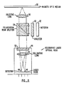
- FIG. 3 is a block diagram of the magneto-optics head according to the present invention.
- a laser pen 44 includes a laser diode 46 and an adjacent photodetector 48, along with a collimating lens 50 and a holographic optical element 52.
- the laser diode is arranged to have polarization parallel to the plane of incidence of a beam-splitter 54 (i.e., the laser beam is p-polarized with respect to the beam-splitter).
- Beam-splitter 54 has the property that it transmits substantially all of p-polarized light and reflects substantially all of s-polarized light.
- the interaction of the localized magnetic domain orientation with the light beam causes the polarization of the reflected beam to be rotated by a small angle.
- the p-polarized light beam after interacting with the medium, now contains a small s-polarized component.
- the light vector's direction of rotation depends on the orientation of the magnetic domain on the medium.
- this reflected beam reenters beam-splitter 54
- 100% of the small s-polarized component is reflected and an equally small amount of p-polarized component is reflected due to the imperfection of beam-splitter 54.
- the polarization orientation of the light beam after reflection by beam-splitter 56 undergoes a large rotation.
- the direction of rotation can easily be analyzed by using an analyzer (polarizer) 60 and a photodetector 62.
- the laser pen of Fig. 3 is shown in Fig. 4.
- This optical head arrangement can be used for different recording mediums, such as a thermal-magnetic medium or a medium using lands and pits.
- a semiconductor laser and detector 68 radiates a laser beam 70 to a collimating lens 72.
- the collimated beam passes through a hologram lens 74 to an objective lens 76.
- Hologram lens 74 can also be put between semiconductor laser and detector 68 and the collimating lens 72.
- Objective lens 76 focuses the beam onto a medium 78.
- Objective lens 76 can be moved by a coil 80 in a focusing and tracking actuator 82.
- Semiconductor laser and detector 68, collimating lens 72 and hologram lens 74 form a laser pen 84 portion of the optical head.
- Fig. 5 shows a front view of the semiconductor laser and photodetector 68.
- a semiconductor laser 86 is mounted on a heat sink 88.
- a four-quadrant photodetector 90 is mounted on the face of heat sink 88.
- a photodetector 92 is located behind semiconductor laser 86 to measure the light emitted from the semiconductor laser. Photodetector 92 is at an angle so that it does not reflect light back into semiconductor laser 86.
- Four-quadrant detector 90 is preferably within 5 millimeters of semiconductor laser 86 and is preferably within 2 mm of the same plane as laser 86.
- a typical manufacturing process results in a photodetector with a thickness of 0.25 to 0.5 mm, and thus a separation of this amount between the photodetector surface and the laser diode face. This separation can be compensated for with a hologram lens combining an astigmatic wavefront for focus error generation and a spherical wavefront similar to a conventional lens. This should place the detector within the focus error range of the optical head.
- laser beam 70 from semiconductor laser 86 is collimated or made parallel by collimating lens 72.
- This collimated beam passes through hologram lens 74 to produce a zero order diffracted beam and a number of higher order diffracted beams.
- the zero order diffracted beam is the one which continues on the same path, and not at an angle, and is the only beam used in the forward light path of the optical head.
- This beam is focused on medium 78 by objective lens 76 which can be moved with coil 80.
- the beam again hits hologram lens 74 producing zero and higher order diffracted beams.
- the zero order beam is returned to the laser and is not used for detection.
- the reflected beam on the return path also produces higher order diffracted beams from holographic lens 74.
- One of these higher order diffracted beams is imaged onto photodetector 90.
- this is the first order diffracted beam which is diffracted by an angle of approximately 10 degrees.
- This structure has the advantage of having the semiconductor laser and photodetector mounted on the same mechanical structure. Thus, motion of this mechanical unit has little effect on the signals received by the optical head because the detector will move in th same amount and direction as th beam will move due to movement of the semiconductor laser.
- Fig. 4 is modular in that laser pen 84 can be replaced separately from focusing and tracking actuator 82.
- the focusing and tracking actuator of Fig. 4 is the same as the focusing and tracking actuator of the prior art.
- hologram lens 74 can also be constructed to perform a tracking and focusing function in conjunction with the photodetector. Such a system is described in parent application Serial No. 938,085.
- Fig. 6 is a top, sectional view of an alternate embodiment of the present invention. Again, the distinction of this embodiment from the prior art is the separate detection of the stored information and the servo error signals. Moreover, the use of another holographic beam-splitter in this embodiment allows the sensing of the polarization rotation of the returned beam by a differential detection method.
- a laser pen 94 directs a p-polarized laser beam through a beam shaping optical element 96 to a 80/20 polarization beam-splitter 98. From there, the beam is directed to a turning mirror 100 which directs the beam out of the page to an actuator not shown for projection onto the magneto-optic media.
- turning mirror 100 directs the light back to beam-splitter 98.
- the 80% of the p-polarized component is passed through beam-splitter 98 and returned to laser pen 94 for producing the servo error signals.
- the s-component generated by the opto-magnetic interaction and 20% of the p-component is directed to a magneto-optic detector module 102.
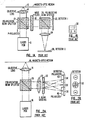
- Fig. 7 is a sectional view along lines 7-7 of Fig. 6 showing the path of the P- component of the laser beam from actuator 104, through mirror 100, through polarization beam-splitter 98, through optical element 96 to the photodetector in laser pen 94.
- Fig. 7 shows the connection of the actuator 104 which includes the objective lens and the mechanisms for moving the objective lens.
- Fig. 8 is a sectional view along lines 8-8 of Fig. 6 showing the path of the S- component from actuator 104 through mirror 100 (not shown) and polarization beam-splitter 98 to magneto-optic detector 102.
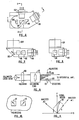
- Fig. 9 shows one embodiment of magneto-optic detector 102 of Fig. 6.
- the Fig. 9 implementation allows the use of an 80/20 beam-splitter where desired.
- This embodiment uses two photodetectors 106, 108 since both P and S components are transmitted, as contrasted with the single photodetector of the embodiment of Fig. 3.
- the laser beam passes through a hologram lens 110 which produces two diffracted beams for impacting photodetectors 106 and 108 after passing through collimating lens 112.
- Polarizers 114 and 116 are placed in front of photodetectors 106 and 108, respectively.
- polarizers 114 and 116 pass components of the laser beam which have orthogonal polarization components.
- a signal vector 118 may be slightly rotated relevant to the P- axis.
- Vector 118 will have components A and B.
- analyzers 114 and 116 pass components in the direction of components A and B, the photodetectors will detect different amplitude signals. Note that it may not be possible to exactly align the analyzers for the P or S component or for the components of the 0.4 degree expected rotation vector. However, such precise alignment is not necessary. Therefore, the difference between the values of the photodetectors provides the detected signal, which is 1 if component A is greater than B and is -1 if component A is less than B.
- the present invention may be embodied in other specific forms without departing form the spirit or essential characteristics thereof.
- the polarizers of Fig. 9 need not be orthogonal.
- one of the photodetectors could be positioned to detect the 0 order (on axis) diffracted beam from hologram lens 110. Accordingly, the disclosure of the preferred embodiment of the invention is intended to be illustrative, but not limiting, of the scope of inven tion which is set forth in the following claims.
Landscapes
- Physics & Mathematics (AREA)
- Optics & Photonics (AREA)
- Optical Recording Or Reproduction (AREA)
- Optical Head (AREA)
Applications Claiming Priority (2)
| Application Number | Priority Date | Filing Date | Title |
|---|---|---|---|
| US141459 | 1988-01-20 | ||
| US07/141,459 US4918675A (en) | 1986-12-04 | 1988-01-20 | Magneto-optical head with separate optical paths for error and data detection |
Publications (2)
| Publication Number | Publication Date |
|---|---|
| EP0325104A2 true EP0325104A2 (de) | 1989-07-26 |
| EP0325104A3 EP0325104A3 (de) | 1991-06-12 |
Family
ID=22495791
Family Applications (1)
| Application Number | Title | Priority Date | Filing Date |
|---|---|---|---|
| EP19890100090 Withdrawn EP0325104A3 (de) | 1988-01-20 | 1989-01-04 | Magneto-optischer Kopf mit getrennten optischen Bahnen für Fehler- und Datendetektion |
Country Status (4)
| Country | Link |
|---|---|
| US (1) | US4918675A (de) |
| EP (1) | EP0325104A3 (de) |
| JP (1) | JPH06101156B2 (de) |
| KR (1) | KR910006661B1 (de) |
Cited By (3)
| Publication number | Priority date | Publication date | Assignee | Title |
|---|---|---|---|---|
| EP0634743A1 (de) * | 1993-07-15 | 1995-01-18 | GOLDSTAR CO. Ltd. | Optische Abtastvorrichtung |
| EP0671734A1 (de) * | 1994-03-08 | 1995-09-13 | Sony Corporation | Optische Vorrichtung |
| EP0731456A3 (de) * | 1995-03-04 | 1996-09-25 | Sony Corp |
Families Citing this family (21)
| Publication number | Priority date | Publication date | Assignee | Title |
|---|---|---|---|---|
| US5155718A (en) * | 1988-01-25 | 1992-10-13 | Olympus Optical Co., Ltd. | Optical record medium reading apparatus having a de-focussed light beam projected on an optical record medium |
| US5315574A (en) * | 1988-10-28 | 1994-05-24 | Matsushita Electric Industrial Co., Ltd. | Optical head with polarized beam hologram |
| US4984229A (en) * | 1988-11-18 | 1991-01-08 | Polaroid Corporation | Autofocus system |
| FR2646245B1 (fr) * | 1989-04-25 | 1991-06-14 | Thomson Csf | Dispositif de lecture optique pour support d'enregistrement optique |
| EP0405444B1 (de) * | 1989-06-26 | 1997-09-03 | Nec Corporation | Optisches System |
| US5218582A (en) * | 1990-12-03 | 1993-06-08 | Eastman Kodak Company | Magneto-optic readout using a polarization-preserving optical guide |
| JPH07114746A (ja) * | 1993-08-25 | 1995-05-02 | Sony Corp | 光学装置 |
| WO1995029483A1 (en) * | 1994-04-23 | 1995-11-02 | Sony Corporation | Magnetooptic recording medium and magnetooptic recording head |
| JP3029541B2 (ja) * | 1994-12-19 | 2000-04-04 | シャープ株式会社 | 光ピックアップ装置 |
| JPH08235663A (ja) * | 1995-02-24 | 1996-09-13 | Sony Corp | 光学素子 |
| JP3544239B2 (ja) * | 1995-03-04 | 2004-07-21 | ソニー株式会社 | 光学ピツクアツプ及び光記録媒体再生装置 |
| US5790291A (en) * | 1995-12-07 | 1998-08-04 | Lucent Technologies Inc. | Beam steering and tracking of laser communication links by dual-quadrant tracker and photodiode assembly |
| JP3732268B2 (ja) * | 1996-02-28 | 2006-01-05 | 富士通株式会社 | 光ディスク装置用光学ヘッド |
| JP3439903B2 (ja) * | 1996-03-11 | 2003-08-25 | 富士通株式会社 | 光ディスク装置用光学ヘッド |
| US5991249A (en) * | 1997-07-29 | 1999-11-23 | Hoetron, Inc. | Optical track sensing device |
| FR2802696B1 (fr) * | 1999-12-17 | 2002-07-19 | Thomson Csf | Lecteur magneto optique optimise par le polariseur de lumiere incidente |
| KR100754160B1 (ko) * | 2001-06-30 | 2007-09-03 | 삼성전자주식회사 | 광디스크 장치 및 워블 신호 재생방법 |
| US6723980B2 (en) | 2001-07-16 | 2004-04-20 | Wai-Hon Lee | Position sensor with grating to detect moving object with periodic pattern |
| US20040090874A1 (en) * | 2002-11-08 | 2004-05-13 | Kunjithapatham Balasubramanian | Apparatus and method for effective reduction of a laser beam spot size |
| JP2005182960A (ja) * | 2003-12-22 | 2005-07-07 | Sharp Corp | 光磁気用の光集積化ユニットおよび光磁気用の光ピックアップ装置 |
| JP5227926B2 (ja) * | 2009-09-16 | 2013-07-03 | 株式会社日立メディアエレクトロニクス | 光ピックアップ装置および光ディスク装置 |
Family Cites Families (16)
| Publication number | Priority date | Publication date | Assignee | Title |
|---|---|---|---|---|
| JPS57111843A (en) * | 1980-12-27 | 1982-07-12 | Canon Inc | Vertical magnetic reading optical system |
| US4504939A (en) * | 1981-12-10 | 1985-03-12 | Discovision Associates | Storage medium track pitch detector |
| US4462095A (en) * | 1982-03-19 | 1984-07-24 | Magnetic Peripherals Inc. | Moving diffraction grating for an information track centering system for optical recording |
| JPS58203646A (ja) * | 1982-05-21 | 1983-11-28 | Canon Inc | 光磁気再生装置 |
| US4558440A (en) * | 1982-08-19 | 1985-12-10 | Canon Kabushiki Kaisha | System for recording patterns of magnetically recorded information by utilizing the magneto-optic effect |
| US4695992A (en) * | 1983-01-31 | 1987-09-22 | Canon Kabushiki Kaisha | Optical information recording-reproducing apparatus in which the relative position of a primary beam and secondary beams on recording medium is varied during recording and reproduction of information |
| JP2504734B2 (ja) * | 1983-11-08 | 1996-06-05 | シャープ株式会社 | 光磁気記憶装置の光学装置 |
| US4670869A (en) * | 1984-01-03 | 1987-06-02 | Magnetic Peripherals Inc. | Switching laser beam apparatus with recombined beam for recording |
| US4689481A (en) * | 1984-06-14 | 1987-08-25 | Nec Corporation | Focus error detector and optical head using the same |
| KR920007294B1 (ko) * | 1984-06-29 | 1992-08-29 | 가부시끼가이샤 히다찌세이사꾸쇼 | 광자기 정보 기록장치의 광헤드 |
| JPS61160845A (ja) * | 1985-01-09 | 1986-07-21 | Nippon Kogaku Kk <Nikon> | 光デイスクの記録再生装置 |
| EP0216341B1 (de) * | 1985-09-27 | 1990-07-04 | Sharp Kabushiki Kaisha | Spurnachlaufverfahren für eine optische Speicherplatte |
| JPS6284456A (ja) * | 1985-10-08 | 1987-04-17 | Mitsubishi Electric Corp | 光磁気記録再生装置 |
| JPS62112246A (ja) * | 1985-11-11 | 1987-05-23 | Sharp Corp | ピツクアツプ装置 |
| US4794585A (en) * | 1986-05-06 | 1988-12-27 | Lee Wai Hon | Optical head having a hologram lens and polarizers for use with magneto-optic medium |
| NL8601974A (nl) * | 1986-08-01 | 1988-03-01 | Philips Nv | Inrichting voor het met optische straling aftasten van een stralingsreflekterend informatievlak. |
-
1988
- 1988-01-20 US US07/141,459 patent/US4918675A/en not_active Expired - Lifetime
-
1989
- 1989-01-04 EP EP19890100090 patent/EP0325104A3/de not_active Withdrawn
- 1989-01-14 KR KR1019890000347A patent/KR910006661B1/ko not_active Expired
- 1989-01-20 JP JP1010118A patent/JPH06101156B2/ja not_active Expired - Lifetime
Cited By (4)
| Publication number | Priority date | Publication date | Assignee | Title |
|---|---|---|---|---|
| EP0634743A1 (de) * | 1993-07-15 | 1995-01-18 | GOLDSTAR CO. Ltd. | Optische Abtastvorrichtung |
| EP0671734A1 (de) * | 1994-03-08 | 1995-09-13 | Sony Corporation | Optische Vorrichtung |
| US5568463A (en) * | 1994-03-08 | 1996-10-22 | Sony Corporation | Semiconductor laser device to detect a divided reflected light beam |
| EP0731456A3 (de) * | 1995-03-04 | 1996-09-25 | Sony Corp |
Also Published As
| Publication number | Publication date |
|---|---|
| KR910006661B1 (ko) | 1991-08-30 |
| KR890012285A (ko) | 1989-08-25 |
| US4918675A (en) | 1990-04-17 |
| JPH01282764A (ja) | 1989-11-14 |
| JPH06101156B2 (ja) | 1994-12-12 |
| EP0325104A3 (de) | 1991-06-12 |
Similar Documents
| Publication | Publication Date | Title |
|---|---|---|
| US4918675A (en) | Magneto-optical head with separate optical paths for error and data detection | |
| US4794585A (en) | Optical head having a hologram lens and polarizers for use with magneto-optic medium | |
| CA1232353A (en) | Optical signal recorders employing two lasers and methods therefor | |
| US4894815A (en) | Optical head for reading information from a magnetooptic recording medium | |
| US4906839A (en) | Hybrid surface emitting laser and detector | |
| US5278817A (en) | Optical pick-up for use with an opto-magnetic signal | |
| US4965780A (en) | Magneto-optical data recording device using a wavelength and polarization-sensitive splitter | |
| US5621716A (en) | Optical pickup having a transparent lens member with two reflecting surfaces | |
| US4785438A (en) | Magneto-optical disc reproducing apparatus with improved two-part head | |
| US5708644A (en) | Optical head for optical disk drive | |
| JPS6332743A (ja) | 光学ヘツド | |
| USRE38648E1 (en) | Magneto-optical recording/reproducing pickup head with a diffraction grating and a wollaston prism | |
| EP0537787B1 (de) | Optisches Abtastgerät | |
| US5119352A (en) | Magneto optic data storage read out apparatus and method | |
| JP3439903B2 (ja) | 光ディスク装置用光学ヘッド | |
| KR100893722B1 (ko) | 광학주사장치 | |
| US5400306A (en) | Differential detection assembly for data retrieval from a data storage disk | |
| US5566157A (en) | Optical pickup for information recording/reproducing apparatus having polygon prism, hologram, and grating lens | |
| CA1275731C (en) | Optical head having a hologram lens and polanzed for use with magnetic-opticmedium | |
| JPS61289545A (ja) | 光ヘツド装置 | |
| JPH02183125A (ja) | 偏光検出器及び光学ヘッド | |
| JPH03212838A (ja) | 高密度ディジタルデータの光磁気記録及び読み出しの方法及び装置 | |
| JPS60193140A (ja) | 光学記憶装置 | |
| JPH0242647A (ja) | 光ピツクアツプ装置 | |
| JPH0711874B2 (ja) | 光磁気信号検出装置 |
Legal Events
| Date | Code | Title | Description |
|---|---|---|---|
| PUAI | Public reference made under article 153(3) epc to a published international application that has entered the european phase |
Free format text: ORIGINAL CODE: 0009012 |
|
| AK | Designated contracting states |
Kind code of ref document: A2 Designated state(s): DE FR GB IT NL SE |
|
| PUAL | Search report despatched |
Free format text: ORIGINAL CODE: 0009013 |
|
| AK | Designated contracting states |
Kind code of ref document: A3 Designated state(s): DE FR GB IT NL SE |
|
| STAA | Information on the status of an ep patent application or granted ep patent |
Free format text: STATUS: THE APPLICATION IS DEEMED TO BE WITHDRAWN |
|
| 18D | Application deemed to be withdrawn |
Effective date: 19910801 |