EP0325140B1 - Caméra à deux objectifs - Google Patents
Caméra à deux objectifs Download PDFInfo
- Publication number
- EP0325140B1 EP0325140B1 EP89100313A EP89100313A EP0325140B1 EP 0325140 B1 EP0325140 B1 EP 0325140B1 EP 89100313 A EP89100313 A EP 89100313A EP 89100313 A EP89100313 A EP 89100313A EP 0325140 B1 EP0325140 B1 EP 0325140B1
- Authority
- EP
- European Patent Office
- Prior art keywords
- focal length
- camera
- length lens
- shutter
- plane
- Prior art date
- Legal status (The legal status is an assumption and is not a legal conclusion. Google has not performed a legal analysis and makes no representation as to the accuracy of the status listed.)
- Expired
Links
- 230000009977 dual effect Effects 0.000 title claims description 11
- 230000003287 optical effect Effects 0.000 claims description 5
- 230000000903 blocking effect Effects 0.000 description 7
- 239000011248 coating agent Substances 0.000 description 2
- 238000000576 coating method Methods 0.000 description 2
- 238000005259 measurement Methods 0.000 description 2
- 230000001154 acute effect Effects 0.000 description 1
- 238000012986 modification Methods 0.000 description 1
- 230000004048 modification Effects 0.000 description 1
Images


Classifications
-
- G—PHYSICS
- G03—PHOTOGRAPHY; CINEMATOGRAPHY; ANALOGOUS TECHNIQUES USING WAVES OTHER THAN OPTICAL WAVES; ELECTROGRAPHY; HOLOGRAPHY
- G03B—APPARATUS OR ARRANGEMENTS FOR TAKING PHOTOGRAPHS OR FOR PROJECTING OR VIEWING THEM; APPARATUS OR ARRANGEMENTS EMPLOYING ANALOGOUS TECHNIQUES USING WAVES OTHER THAN OPTICAL WAVES; ACCESSORIES THEREFOR
- G03B19/00—Cameras
- G03B19/02—Still-picture cameras
- G03B19/04—Roll-film cameras
- G03B19/07—Roll-film cameras having more than one objective
Definitions
- the invention generally relates to the field of photography. More particularly, it relates to a dual lens camera of the type wherein a relatively longer focal length lens and a relatively shorter focal length lens are selectively used to expose film in the camera, for example to take a telephoto or a wide angle picture.
- FIG. 1 of the accompanying drawings A dual lens camera typical of the prior art (for instance US-A-4,589,748) is partially illustrated in FIG. 1 of the accompanying drawings.
- the camera has a relatively longer focal length lens 1 and a relatively shorter focal length lens 3, either one of which is selectively used for telephoto and wide angle photography.
- a fixed mirror 5 is permanently located behind the longer focal length lens 1, and a movable mirror 7 is positionable behind the shorter focal length lens 3 in facing parallel relation to the fixed mirror.
- the movable mirror 7 in this position has a matte black coating 9 on its rear side which is disposed to block ambient light entering the shorter focal length lens 3 to prevent the light from reaching an exposure plane 11 (also referred to as a film plane) proximate a rear door 13 of the camera.
- an exposure plane 11 also referred to as a film plane
- the two mirrors 5 and 7 define a Z-shaped light-ray path (i.e., one that bends at angles of less than 90 o ) X, Y, Z from the longer focal length lens 1 to the exposure plane 11.
- the movable mirror 7 may be pivoted in a clockwise direction in FIG. 1 about a mounting pin 15, out of its blocking position behind the shorter focal length lens 3 to a non-blocking position depicted in broken line, to allow ambient light entering the shorter focal length lens to pass straight through to the exposure plane 11. In the non-blocking position, the movable mirror 7 deflects ambient light reflected by the fixed mirror 5 from the longer focal length lens 1 to prevent the light from reaching the exposure plane 11.
- the alternate positions of the movable mirror 7 determine which one of the two lenses is used.
- a shutter and/or aperture plane defining plate 17 is disposed with respective open portions 19 and 21 of the plate optically aligned with the longer and shorter focal length lens 1 and 3.
- the plate 17 is located between the two lenses 1 and 3 and the exposure plane 11, and it is supported parallel to the exposure plane and a front face 23 of the camera. Since the longer focal length lens 1 is greater lengthwise than the shorter focal length lens 3, the arrangement of the plate 17 parallel to the exposure plane 11 appears to necessitate a front to rear dimension D of the camera that prevents making the camera very compact in size.
- the invention is believed to solve the above-described problem existing in known dual lens cameras by providing a dual lens camera of the type comprising (a) a relatively longer focal length lens and a relatively shorter focal length lens both positioned proximate the front of said camera, said lenses having substantially parallel optical axes and being selectively used to expose film at an exposure plane positioned proximate the rear of said camera, and (b) shutter and/or aperture plane defining means having respective portions optically aligned with said longer and shorter focal length lenses and being positioned between said front of the camera and said exposure plane, and wherein the improvement comprises: means supporting said shutter and/or aperture plane defining means inclined towards said exposure plane in a manner such that said portion of the shutter and/or aperture plane defining means aligned with said longer focal length lens is closer to said exposure plane than said portion of the shutter and/or aperture plane defining means aligned with said shorter focal length lens, whereby a front to rear dimension of said camera will be reduced.
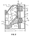
- FIG. 2 of the drawings An improved dual lens camera according to a preferred embodiment of the invention is partially illustrated in FIG. 2 of the drawings.
- the improved camera is generally indicated by the reference number 31, and to the extent it includes certain elements similar to those included in the prior art camera of FIG. 1 the elements are indicated by the same reference numbers as in FIG. 1 but followed by a prime (') designation.
- the improved camera 31 has a relatively longer focal length lens 1' and a relatively shorter focal length lens 3', either one of which is selectively used for telephoto and wide angle photography.
- a fixed mirror 5' is permanently located behind the longer focal length lens 1', and a movable mirror 7' is positionable behind the shorter focal length lens 3' in facing parallel relation to the fixed mirror.
- the movable mirror 7' in this position has a matte black coating 9' on its rear side which is disposed to block ambient light entering the shorter focal length lens 3' to prevent the light from reaching an exposure plane 11' (also referred to as a film plane) proximate a rear door 13' of the camera 31.
- an exposure plane 11' also referred to as a film plane
- the two mirrors 5' and 7' define a Z-shaped light-ray path (i.e., one that bends at angles of less than 90 degrees) X', Y', Z' from the longer focal length lens 1' to the exposure plane 11'.
- the movable mirror 7' may be pivoted in a clockwise direction about a mounting pin 15', out of its blocking position behind the shorter focal length lens 3' to a non-blocking position, to allow ambient light entering the shorter focal length lens to pass straight through to the exposure plane 11'. In the non-blocking position, the movable mirror 7' deflects ambient light reflected by the fixed mirror 5' from the longer focal length lens 1' to prevent the light from reaching the exposure plane 11'.
- the alternate positions of the movable mirror 7' shown in FIGS. 2 and 3 determine which one of the two lenses 1' and 3' is used.
- the Z-shaped light-ray path X', Y', Z' from the longer focal length lens 1' to the exposure plane 11' has its first component X' aligned with the optical axis 33 of the longer focal length lens, its third component Z' aligned with the optical axis 35 of the shorter focal length lens 3', and its second component Y' forming the same acute angle ⁇ with the first and third components.
- the first component X' is measured from the longer focal length lens 1' to the fixed mirror 5'.
- the second component Y' is measured from the fixed mirror 5' to the movable mirror 7' (in its blocking position).
- the third component Z' is measured from the movable mirror 7' to the exposure plane 11'.
- the arrangement of the shutter and/or aperture plane defining plate 17' inclined inwardly towards the exposure plane 11' provides additional interior space for the longer focal length lens. This space allows the longer focal length lens 1' to be positioned further inwardly as compared to the longer focal length lens 1 in FIG. 1.
- the front to rear dimension D' of the improved camera 31 of FIG. 2 can be made less than the corresponding dimension D of the prior art camera of FIG. 1.
- a brief comparison of the Z-shaped light-ray path X', Y', Z' in FIG. 2 with the Z-shaped light-ray path X, Y, Z in FIG. 1 is noteworthy.
- the sum of the components X' and Y' and Z' is equal to the sum of the components X and Y and Z.
- the component X' is less than the component X.
- the component Y' is greater than the component Y.
- the component Z' is equal to the component Z. Consequently, the front to rear dimension D' in FIG. 2 can be made less than the corresponding dimension D in FIG. 1 by the difference X - X' or ⁇ .
- the shutter and/or aperture plane defining plate 17' can be located between the two lenses 1' and 3' and the front face 23' of the improved camera 31.
- the front face 23' would be disposed parallel to the plate 17', and therefore it would be inclined towards the exposure plane 11'.
- the open portions 19' and 21' of the shutter and/or aperture defining plate 17' need not be co-planar. All that is required is that the open portion 19' be located closer to the exposure plane 11' than is the open portion 21'.
Landscapes
- Physics & Mathematics (AREA)
- General Physics & Mathematics (AREA)
- Cameras In General (AREA)
- Diaphragms For Cameras (AREA)
- Structure And Mechanism Of Cameras (AREA)
Claims (3)
- Appareil photographique (31) à deux objectifs, comprenant un objectif présentant une distance focale relativement longue (1') et un objectif présentant une distance focale relativement courte, les deux objectifs étant situés au voisinage de l'avant (23') de l'appareil, ayant leur axe optique pratiquement parallèle l'un à l'autre, étant utilisé sélectivement pour exposer le film disposé au niveau du plan d'exposition (11') situé au voisinage du dos (13') de l'appareil, et un moyen (17', 19') d'obturation et/ou de diaphragme présentant des parties respectives optiquement alignées avec les objectifs à longue et courte focale (1', 3') et étant disposé entre l'avant de l'appareil et le plan d'exposition, appareil caractérisé en ce que le moyen d'obturation et/ou de diaphragme (17', 19') est incliné vers ledit plan d'exposition (17') de manière que ladite partie du moyen d'obturation et/ou de diaphragme alignée avec l'objectif (1') de focale la plus longue est plus près du plan d'exposition (11') que la partie du moyen d'obturation et/ou de diaphragme (17', 19') aligné avec l'objectif (3') de focale la plus petite de manière que la distance (D') entre l'avant de l'appareil et le plan d'exposition soit réduite.
- Appareil selon la revendication 1, dans lequel l'objectif (1') de focale la plus longue est situé de manière à occuper l'espace qui aurait été occupé par la partie du moyen d'obturation et/ou de diaphragme (17', 19') alignée avec ledit objectif de focale la plus longue si le moyen d'obturation et/ou de diaphragme avait été supporté de manière à être pratiquement parallèle au plan d'exposition (11') au lieu d'être incliné par rapport à ce dit plan d'exposition.
- Appareil selon l'une des revendications 1 ou 2, dans lequel le moyen d'obturation et/ou de diaphragme (17', 19') est situé entre les objectifs (1', 3') de focales longue et courte et le plan d'exposition (11').
Applications Claiming Priority (2)
| Application Number | Priority Date | Filing Date | Title |
|---|---|---|---|
| US145332 | 1988-01-19 | ||
| US07/145,332 US4801958A (en) | 1988-01-19 | 1988-01-19 | Dual lens camera |
Publications (2)
| Publication Number | Publication Date |
|---|---|
| EP0325140A1 EP0325140A1 (fr) | 1989-07-26 |
| EP0325140B1 true EP0325140B1 (fr) | 1992-12-23 |
Family
ID=22512607
Family Applications (1)
| Application Number | Title | Priority Date | Filing Date |
|---|---|---|---|
| EP89100313A Expired EP0325140B1 (fr) | 1988-01-19 | 1989-01-10 | Caméra à deux objectifs |
Country Status (5)
| Country | Link |
|---|---|
| US (1) | US4801958A (fr) |
| EP (1) | EP0325140B1 (fr) |
| JP (1) | JPH01223433A (fr) |
| DE (1) | DE68903956T2 (fr) |
| HK (1) | HK85493A (fr) |
Families Citing this family (10)
| Publication number | Priority date | Publication date | Assignee | Title |
|---|---|---|---|---|
| JP3544239B2 (ja) * | 1995-03-04 | 2004-07-21 | ソニー株式会社 | 光学ピツクアツプ及び光記録媒体再生装置 |
| JPH09133960A (ja) * | 1995-11-07 | 1997-05-20 | Fuji Photo Optical Co Ltd | 二焦点切替えカメラ |
| US5960218A (en) * | 1997-02-18 | 1999-09-28 | Mobi Corporation | Dual focal length camera |
| JP4503933B2 (ja) * | 2003-03-13 | 2010-07-14 | オリンパス株式会社 | 撮像装置 |
| US6924948B2 (en) * | 2003-08-21 | 2005-08-02 | Arc Design, Inc. | Multifocal lens system for digital cameras |
| JP4513691B2 (ja) * | 2005-08-23 | 2010-07-28 | 株式会社デンソー | 撮像モジュール |
| KR100749337B1 (ko) * | 2006-06-13 | 2007-08-14 | 삼성전자주식회사 | 복수의 카메라렌즈를 구비한 이동통신단말기를 이용한 촬영방법 및 장치 |
| CN107820576A (zh) | 2015-06-29 | 2018-03-20 | Lg伊诺特有限公司 | 双相机模块及光学装置 |
| KR102389392B1 (ko) * | 2015-06-30 | 2022-04-22 | 엘지이노텍 주식회사 | 듀얼 카메라 모듈 및 광학기기 |
| CN107340668B (zh) | 2016-04-28 | 2019-11-19 | 台湾东电化股份有限公司 | 双镜头照相系统 |
Family Cites Families (9)
| Publication number | Priority date | Publication date | Assignee | Title |
|---|---|---|---|---|
| US2148011A (en) * | 1938-02-11 | 1939-02-21 | James P Burke | Camera and method of photography |
| US3008399A (en) * | 1959-05-29 | 1961-11-14 | Bergerhoff Hugo | Focal plane shutter for photographic cameras |
| US3044375A (en) * | 1960-04-01 | 1962-07-17 | Leitz Ernst Gmbh | Camera with built-in exposure meter |
| FR1319337A (fr) * | 1962-01-15 | 1963-03-01 | Commissariat Energie Atomique | Dispositif obturateur à ouverture ultra-rapide |
| US3535995A (en) * | 1968-06-10 | 1970-10-27 | Us Army | Ball shutter |
| US4204758A (en) * | 1978-11-20 | 1980-05-27 | John Hadland (Photograph Instrumentation) Ltd. | Closure mechanism such as a camera shutter |
| US4249814A (en) * | 1979-10-01 | 1981-02-10 | Iowa State University Research Foundation, Inc. | Frustrated total internal reflection camera shutter |
| JPS59144646U (ja) * | 1983-03-18 | 1984-09-27 | 富士写真フイルム株式会社 | レンズ切替カメラ |
| JPS59153527U (ja) * | 1983-03-31 | 1984-10-15 | 富士写真フイルム株式会社 | レンズ切替カメラの露出調節装置 |
-
1988
- 1988-01-19 US US07/145,332 patent/US4801958A/en not_active Expired - Fee Related
-
1989
- 1989-01-10 DE DE8989100313T patent/DE68903956T2/de not_active Expired - Fee Related
- 1989-01-10 EP EP89100313A patent/EP0325140B1/fr not_active Expired
- 1989-01-19 JP JP1010976A patent/JPH01223433A/ja active Pending
-
1993
- 1993-08-19 HK HK854/93A patent/HK85493A/xx unknown
Also Published As
| Publication number | Publication date |
|---|---|
| DE68903956D1 (de) | 1993-02-04 |
| HK85493A (en) | 1993-08-27 |
| EP0325140A1 (fr) | 1989-07-26 |
| US4801958A (en) | 1989-01-31 |
| JPH01223433A (ja) | 1989-09-06 |
| DE68903956T2 (de) | 1993-06-17 |
Similar Documents
| Publication | Publication Date | Title |
|---|---|---|
| US4801958A (en) | Dual lens camera | |
| JPH0342429Y2 (fr) | ||
| US5130855A (en) | Viewfinder optical system | |
| US4772903A (en) | Dual lens camera | |
| US4609270A (en) | Camera with interchangeable taking lenses | |
| US4912500A (en) | Single lens reflex camera | |
| US6535340B1 (en) | Optical element and picture taking system including the optical element | |
| US3788202A (en) | Viewfinder for single lens reflex cameras | |
| US4547047A (en) | Microscope tube system | |
| US6122455A (en) | Lensless viewfinder and lensless viewfinder camera | |
| US4064516A (en) | Reflex camera light detecting arrangement | |
| US4931818A (en) | Camera view finder | |
| US6314246B1 (en) | Viewfinder optical system of a single-lens reflex camera | |
| JPS61114217A (ja) | 撮影光学系 | |
| US4609272A (en) | Finder system of high image magnification | |
| US4431285A (en) | Movable mirror arrangement for use in single lens reflex camera | |
| US3052169A (en) | Viewfinder for single lens reflex cameras | |
| US5668919A (en) | Camera | |
| US4119985A (en) | View finder for reflex camera | |
| US5572013A (en) | Focus detection apparatus with a light shielding member | |
| JPH0359626A (ja) | カメラシステム | |
| US4437740A (en) | Quick return beam splitter for a single lens reflex camera | |
| US4032938A (en) | Miniature single lens reflex camera | |
| US4428653A (en) | Mirror reflex camera with an electronic range finder | |
| US3127463A (en) | Photographic viewfinder with divided field frame and imaging means |
Legal Events
| Date | Code | Title | Description |
|---|---|---|---|
| PUAI | Public reference made under article 153(3) epc to a published international application that has entered the european phase |
Free format text: ORIGINAL CODE: 0009012 |
|
| AK | Designated contracting states |
Kind code of ref document: A1 Designated state(s): DE FR GB |
|
| 17P | Request for examination filed |
Effective date: 19900118 |
|
| 17Q | First examination report despatched |
Effective date: 19920508 |
|
| GRAA | (expected) grant |
Free format text: ORIGINAL CODE: 0009210 |
|
| AK | Designated contracting states |
Kind code of ref document: B1 Designated state(s): DE FR GB |
|
| REF | Corresponds to: |
Ref document number: 68903956 Country of ref document: DE Date of ref document: 19930204 |
|
| ET | Fr: translation filed | ||
| PLBE | No opposition filed within time limit |
Free format text: ORIGINAL CODE: 0009261 |
|
| STAA | Information on the status of an ep patent application or granted ep patent |
Free format text: STATUS: NO OPPOSITION FILED WITHIN TIME LIMIT |
|
| 26N | No opposition filed | ||
| PGFP | Annual fee paid to national office [announced via postgrant information from national office to epo] |
Ref country code: GB Payment date: 19941221 Year of fee payment: 7 |
|
| PGFP | Annual fee paid to national office [announced via postgrant information from national office to epo] |
Ref country code: FR Payment date: 19950117 Year of fee payment: 7 |
|
| PGFP | Annual fee paid to national office [announced via postgrant information from national office to epo] |
Ref country code: DE Payment date: 19950203 Year of fee payment: 7 |
|
| PG25 | Lapsed in a contracting state [announced via postgrant information from national office to epo] |
Ref country code: GB Effective date: 19960110 |
|
| GBPC | Gb: european patent ceased through non-payment of renewal fee |
Effective date: 19960110 |
|
| PG25 | Lapsed in a contracting state [announced via postgrant information from national office to epo] |
Ref country code: FR Effective date: 19960930 |
|
| PG25 | Lapsed in a contracting state [announced via postgrant information from national office to epo] |
Ref country code: DE Effective date: 19961001 |
|
| REG | Reference to a national code |
Ref country code: FR Ref legal event code: ST |