EP0325212A2 - Tête de fraisage - Google Patents
Tête de fraisage Download PDFInfo
- Publication number
- EP0325212A2 EP0325212A2 EP89100736A EP89100736A EP0325212A2 EP 0325212 A2 EP0325212 A2 EP 0325212A2 EP 89100736 A EP89100736 A EP 89100736A EP 89100736 A EP89100736 A EP 89100736A EP 0325212 A2 EP0325212 A2 EP 0325212A2
- Authority
- EP
- European Patent Office
- Prior art keywords
- insert holder
- eccentric sleeve
- cutter head
- base body
- insert
- Prior art date
- Legal status (The legal status is an assumption and is not a legal conclusion. Google has not performed a legal analysis and makes no representation as to the accuracy of the status listed.)
- Granted
Links
Images



Classifications
-
- B—PERFORMING OPERATIONS; TRANSPORTING
- B23—MACHINE TOOLS; METAL-WORKING NOT OTHERWISE PROVIDED FOR
- B23C—MILLING
- B23C5/00—Milling-cutters
- B23C5/16—Milling-cutters characterised by physical features other than shape
- B23C5/20—Milling-cutters characterised by physical features other than shape with removable cutter bits or teeth or cutting inserts
- B23C5/22—Securing arrangements for bits or teeth or cutting inserts
- B23C5/24—Securing arrangements for bits or teeth or cutting inserts adjustable
- B23C5/2486—Securing arrangements for bits or teeth or cutting inserts adjustable where the adjustment is made by elastically deforming the toolholders
-
- B—PERFORMING OPERATIONS; TRANSPORTING
- B23—MACHINE TOOLS; METAL-WORKING NOT OTHERWISE PROVIDED FOR
- B23C—MILLING
- B23C5/00—Milling-cutters
- B23C5/16—Milling-cutters characterised by physical features other than shape
- B23C5/20—Milling-cutters characterised by physical features other than shape with removable cutter bits or teeth or cutting inserts
- B23C5/22—Securing arrangements for bits or teeth or cutting inserts
- B23C5/24—Securing arrangements for bits or teeth or cutting inserts adjustable
- B23C5/2472—Securing arrangements for bits or teeth or cutting inserts adjustable the adjusting means being screws
-
- B—PERFORMING OPERATIONS; TRANSPORTING
- B23—MACHINE TOOLS; METAL-WORKING NOT OTHERWISE PROVIDED FOR
- B23C—MILLING
- B23C5/00—Milling-cutters
- B23C5/16—Milling-cutters characterised by physical features other than shape
- B23C5/20—Milling-cutters characterised by physical features other than shape with removable cutter bits or teeth or cutting inserts
- B23C5/22—Securing arrangements for bits or teeth or cutting inserts
- B23C5/24—Securing arrangements for bits or teeth or cutting inserts adjustable
- B23C5/2479—Securing arrangements for bits or teeth or cutting inserts adjustable the adjusting means being eccentrics
-
- Y—GENERAL TAGGING OF NEW TECHNOLOGICAL DEVELOPMENTS; GENERAL TAGGING OF CROSS-SECTIONAL TECHNOLOGIES SPANNING OVER SEVERAL SECTIONS OF THE IPC; TECHNICAL SUBJECTS COVERED BY FORMER USPC CROSS-REFERENCE ART COLLECTIONS [XRACs] AND DIGESTS
- Y10—TECHNICAL SUBJECTS COVERED BY FORMER USPC
- Y10T—TECHNICAL SUBJECTS COVERED BY FORMER US CLASSIFICATION
- Y10T407/00—Cutters, for shaping
- Y10T407/19—Rotary cutting tool
- Y10T407/1906—Rotary cutting tool including holder [i.e., head] having seat for inserted tool
- Y10T407/1908—Face or end mill
- Y10T407/192—Face or end mill with separate means to fasten tool to holder
-
- Y—GENERAL TAGGING OF NEW TECHNOLOGICAL DEVELOPMENTS; GENERAL TAGGING OF CROSS-SECTIONAL TECHNOLOGIES SPANNING OVER SEVERAL SECTIONS OF THE IPC; TECHNICAL SUBJECTS COVERED BY FORMER USPC CROSS-REFERENCE ART COLLECTIONS [XRACs] AND DIGESTS
- Y10—TECHNICAL SUBJECTS COVERED BY FORMER USPC
- Y10T—TECHNICAL SUBJECTS COVERED BY FORMER US CLASSIFICATION
- Y10T407/00—Cutters, for shaping
- Y10T407/19—Rotary cutting tool
- Y10T407/1906—Rotary cutting tool including holder [i.e., head] having seat for inserted tool
- Y10T407/1932—Rotary cutting tool including holder [i.e., head] having seat for inserted tool with means to fasten tool seat to holder
-
- Y—GENERAL TAGGING OF NEW TECHNOLOGICAL DEVELOPMENTS; GENERAL TAGGING OF CROSS-SECTIONAL TECHNOLOGIES SPANNING OVER SEVERAL SECTIONS OF THE IPC; TECHNICAL SUBJECTS COVERED BY FORMER USPC CROSS-REFERENCE ART COLLECTIONS [XRACs] AND DIGESTS
- Y10—TECHNICAL SUBJECTS COVERED BY FORMER USPC
- Y10T—TECHNICAL SUBJECTS COVERED BY FORMER US CLASSIFICATION
- Y10T407/00—Cutters, for shaping
- Y10T407/22—Cutters, for shaping including holder having seat for inserted tool
- Y10T407/227—Cutters, for shaping including holder having seat for inserted tool with separate means to fasten tool seat to holder
Definitions
- the invention relates to a cutter head with an essentially cylindrical base body, which, opposite to a machine holder, has a plurality of recesses which are accessible on the end face and radially for receiving an axially and radially adjustable insert holder with at least one associated insert.
- Knife heads for the execution of milling work which are equipped with hard metal cutting edges or cutting plate supports can be adjusted in relation to the base body with regard to their cutting elements.
- the axial and / or radial adjustment of the insert carriers to ensure high tool accuracy must be possible with the highest precision, since the low wear of the cutting elements and inserts requires adjustment options in the ⁇ m range with regard to concentricity and axial runout of the cutter head.
- the invention is therefore based on the object of creating a cutter head of the type mentioned, in which radial or axial readjustment of the cutting elements of the cutter head is possible in an uncomplicated manner to ensure an exact tool size and secure positioning of the cutting elements on the base body of the cutter head during the machining operation is accomplished.
- the insert holder has an axial guide shaft and a insert holder, the guide shaft is received in an eccentric sleeve and coupled to it axially adjustable, the eccentric sleeve is axially fixed in the base body and is rotatable relative to the base body and to the insert holder and the insert holder can be locked by means of a radial clamping device.
- a preferred embodiment of the invention which enables a continuous radial and axial readjustment of each insert holder and thus of the respective insert connected to it, is evident characterized in that the eccentric sleeve has an inner bore eccentric to its outer surface, in which the guide shaft of the insert holder is received in a clearance fit. Furthermore, the eccentric sleeve is rotatably received in a clearance fit in a basic bore of the base body, a fixing bolt engages in the eccentric sleeve, and the eccentric sleeve is received in the base body of the cutter head in an axially resilient manner.
- the eccentric sleeve is provided with a first slot which extends in the circumferential direction and into which a fixing bolt engages radially through the base body.
- a further slot extending axially and circumferentially is provided on the eccentric sleeve, through which a wedge bolt penetrating radially through the base body comes into contact is brought to a mating wedge surface of the guide shaft of the insert holder.
- the eccentric sleeve For easy execution of a rotation of the eccentric sleeve in the circumferential direction for the purpose of radial adjustment of the respective insert holder, the eccentric sleeve preferably has a tab extending into the area of the end face of the base body with an engagement groove for the attachment of a tool that can be used for the rotary adjustment of the eccentric sleeve.
- an advantageous embodiment of the axial adjustment according to the invention for the insert holder Associated insert is achieved in that the insert holder is provided at its opposite end facing away from the insert holder with an enlarged internal thread section of an axial threaded hole, in which an adjusting screw engages from below, which at the same time acts as a counter-bearing for a plate spring that is prestressed between the screw head and an end face of the eccentric sleeve forms the serves to compensate for play between the eccentric sleeve and its fixing bolt.
- the screw head rests on the bottom of the mounting hole.
- To actuate the set screw when the insert holder is mounted it is provided with an internal hexagon in the end face of the threaded shaft, into which an Allen key can be inserted from the outside through the axial threaded bore of the insert holder.
- grub screws of different lengths and / or densities can preferably be screwed into the axial threaded bore of the respective insert holder from the outside.
- FIG. 1 shows a perspective view of a cutter head 1 consisting of a base body 2 and a machine holder 3, the base body 2 having recesses 4 which open at the end and radially outwards, in each of which a cutting arrangement 5 is accommodated.
- the recesses 4 include base bores 6, not shown here, which each extend axially into the base body 2 and serve to accommodate the cutting arrangements 5, so that the cutting arrangements 5 can be inserted and accommodated in the base body 2 of the cutter head 1, and face cutting of Cutting plates 14 of the cutting arrangements 5 are arranged in the fully assembled state near a front end face plane of the base body 2.
- a cutting arrangement 5 is shown in an exploded view, while the other two cutting arrangements 5 are in their fully assembled state on the base body 2 of the cutter head 1.
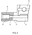
- the cutting arrangement 5 has a cutting plate carrier 8, which is shown in detail in FIG. 2 and has an axial guide shaft 9 and a cutting plate receptacle 10 adjoining this at one end of the cutting plate carrier 8.
- the cutting plate designed as a hard metal, PCD or ceramic plate is fastened to the cutting plate receptacle 10 by a retaining screw 15. The additional securing of the cutting plate 14 against centrifugal or centripetal forces is achieved by receiving the cutting plate 14 and the cutting plate receptacle 10 via a groove connection.
- the insert holder 8 has an axial threaded bore 12 which extends centrally through the guide shaft and the head region on the insert side and an internally threaded section 13 which widens at the end of the guide shaft 9.
- the end-side internal thread section 13 serves to receive an adjusting screw 24 for the axial adjustment of the insert holder 8 relative to the base body 2, while the threaded bore 12 on the one hand provides access to a turning tool for the adjusting screw 24 for its screw actuation and on the other hand the reception of Compensating set screws 17 for compensating for possible imbalance of the cutter head 1.
- the insert holder 8 is accommodated with its guide shaft 9 in an eccentric inner bore 18 of an eccentric sleeve 17 in a play fit, the eccentric sleeve 17 being axially compensated by a plate spring 23 by means of a fixing bolt 27 is fixed in the base body 2 and the plate spring is supported on an end face 21 of the eccentric sleeve 17 and on the screw head 25 of an adjusting screw 24 which can be screwed into the internal thread section 13 of the guide shaft 9.
- the head 25 of the adjusting screw 24 rests on the bottom of the basic bore 6.
- the eccentric sleeve 17 functioning as a radial adjustment sleeve is shown in detail in FIGS. 3 and 4.
- the eccentric sleeve 17 has an inner bore 18 that runs eccentrically to its outer circumference with a coaxial passage opening 18a in an end face 21 of the eccentric sleeve 17. Furthermore, the eccentric sleeve 18 has a projecting tab 22 with an end engagement groove 31 on. Finally, the eccentric sleeve 17 has axially and circumferentially offset slots 19, 20 which each extend in the circumferential direction.
- the slot 19 is used to fix the position of the eccentric sleeve 17 axially in the base body 2 of the cutter head 1 with the aid of a fixing bolt 27 which penetrates this radially and is secured by a threaded pin 28.
- the eccentric sleeve 17 is axially prestressed by the plate spring 23 against the fixing bolt 27 and the eccentric sleeve 17 is received in a play fit in the basic bore 6 of the base body 2 opening into the associated recess 4.
- the further slot 20 allows a wedge bolt 29, which is inserted after inserting the cutting arrangement 5 into the base body 2 with the aid of a setscrew 30 radially into the base body 2 via a clamping bore 7 cutting the base bore, in direct chip contact with the guide shaft 9 of the insert holder 8 to occur in the area of a clamping surface 11 of the guide shaft 9.
- the clamping surface 11 is machined on the guide shaft 9 and becomes the wedge pin 29 so that the entire cutting arrangement 5 is fastened in the base body 2 in such a way that the insert holder 8 with the eccentric sleeve 17 in the receiving base bore 6 of the base body 2 is braced against it essentially radially outward, so that centripetal forces which occur due to rotation only increase an even firmer contact of the cutting device 5 on the base body 2 in the clamping direction and dynamic loads on the cutter head 4 do not lead to a change in position of the cutting plates 14 set in the ⁇ m range.
- FIG. 5 shows, in a further embodiment of the invention, on the basis of a cutting arrangement 5 shown in an exploded view, the use of a cutting plate carrier 8 which has been modified compared to the arrangement according to FIG. 1, in that it has a cutting plate receptacle 10 with soldered hard metal or another cutting material plate 14.
- the cutting plate or cutting edge 14 thus forms an integral bond with the cutting plate carrier 8, which can contribute to a further increase in the setting accuracy of the cutter head 1.
- the cutting arrangement 5, with its associated holding and adjusting means corresponds completely to the exemplary embodiment shown in FIG. 1, matching parts also being provided with the same reference numerals and reference being made to the above explanations with regard to their structure and design.
- the cutting arrangement 5 For the purpose of axially and radially adjustable fastening of the cutting assembly 5 in the Base body 2 of the cutter head 1 is first preassembled the cutting arrangement 5 such that the insert holder 8 with the insert 14 attached to it is inserted with its guide shaft 9 into the inner bore 18 of the eccentric sleeve 17 and, with the disc spring 23 interposed, the set screw 24 into the internally threaded section 13 of the guide shaft 9 is screwed in, so that the entire cutting arrangement 5 forms an insert which can be inserted jointly into the recess 4 with the associated basic bore of the basic body 2.
- the adjusting screw 25 is screwed into the internal thread section 13 at least to the extent that the prestressing force of the plate spring 23 is effective between the screw head 25 of the adjusting screw 24 and the eccentric sleeve 17 and the eccentric sleeve 17 preferably still maintains a certain degree of axial mobility in the direction of the screw head 25 of the adjusting screw 24 .
- the depth of the base bore 6 of the base body 2 in the recess 4 is designed with respect to the radial bore (not shown here) for receiving the fixing bolt 27 so that when the preassembled cutting arrangement 5 or the eccentric sleeve 17 is inserted, the slot 19 against the biasing force of the plate spring 23 the eccentric sleeve 17 is in alignment with the radial bore for receiving the fixing bolt 27 and this is inserted into the base body 2 and engages in the slot 19 of the eccentric sleeve 17, so that the eccentric sleeve 17 is biased axially by the plate spring 23 against the fixing bolt 27 in the To fix the base body 2 axially, the fixing bolt 27 then being fixed and secured by the setscrew 28. In this way, the entire cutting arrangement 5 is simultaneously received and fixed in the base body 2.
- a radial adjustment of the insert holder 8 can now take place in that the eccentric sleeve 17 is rotated relative to the insert holder 8.
- a special key 32 (see FIGS. 1 and 5) is used, which engages with a threadless guide pin 33 in the threaded bore 12 and can be brought into engagement with the engagement groove 31 of the eccentric sleeve 17 with an engagement lug 34. Due to the eccentric mounting of the insert holder 8 in the eccentric sleeve 17, a rotary adjustment thereof leads to a radial movement of the insert holder 8 and thus the associated insert in relation to the base body 2 of the cutter head 1.
- the bracing is carried out in such a way that a clamping force which is effective radially outward against the base body is generated in order to avoid dynamic influencing when the cutter head is rated at a high peripheral speed in order to achieve the high cutting speeds which are desirable for the machining process.
- the cutting plates 14 are set in a corresponding manner for the further cutting arrangements 5; in the present case, the cutter head 1 is equipped with 3 cutting arrangements 5, each offset by 120 °.
- the axial fixing of the eccentric sleeves 17 via the fixing bolts 27 also makes it possible to remove the respective insert holder 8 from the base body 2, the associated eccentric sleeve, plate spring 23 and set screw 24 in the respective base bore 6 with the set screw 24 in contact with the base of the base bore 6 remain. This enables the cutting plate carrier 8 to be exchanged quickly and easily if necessary.
- unbalanced screws 17 of different lengths or of different materials of different densities can be screwed into the axial threaded bore 12 of the respective insert holder 8 and can also be closed to the outside by this threaded bore 12.
- the initial assembly of the cutting arrangements 5 on the base body 2 of the cutter head 1 can also be carried out in such a way that subsequently the set screw 25, the plate spring 23 and the eccentric sleeve 17 are loosely inserted into the relevant basic bore and, under axial prestressing of the plate spring 23, the eccentric sleeve 17 radially with the aid of Fixing bolt 27 and the setscrew 28 is fixed, in order to then subsequently insert the insert holder 8 and screw it under axial adjustment with the adjusting screw 25 by actuating the adjusting screw 24 via the hexagon socket 26 thereof.
- the invention is of course not limited to the exemplary embodiments shown, but can in particular constructive changes in relation to the insert holder 8 and the insert holder 10 and e.g. with respect to the fixing and chip arrangement 27, 28, 29, 30, which can also be combined to form a common functional element.
Landscapes
- Engineering & Computer Science (AREA)
- Mechanical Engineering (AREA)
- Milling Processes (AREA)
- Drilling Tools (AREA)
- Finish Polishing, Edge Sharpening, And Grinding By Specific Grinding Devices (AREA)
- Nonmetal Cutting Devices (AREA)
Priority Applications (1)
| Application Number | Priority Date | Filing Date | Title |
|---|---|---|---|
| AT89100736T ATE104189T1 (de) | 1988-01-19 | 1989-01-17 | Messerkopf. |
Applications Claiming Priority (2)
| Application Number | Priority Date | Filing Date | Title |
|---|---|---|---|
| DE3801394A DE3801394A1 (de) | 1988-01-19 | 1988-01-19 | Messerkopf |
| DE3801394 | 1988-01-19 |
Publications (3)
| Publication Number | Publication Date |
|---|---|
| EP0325212A2 true EP0325212A2 (fr) | 1989-07-26 |
| EP0325212A3 EP0325212A3 (fr) | 1991-01-09 |
| EP0325212B1 EP0325212B1 (fr) | 1994-04-13 |
Family
ID=6345540
Family Applications (1)
| Application Number | Title | Priority Date | Filing Date |
|---|---|---|---|
| EP89100736A Expired - Lifetime EP0325212B1 (fr) | 1988-01-19 | 1989-01-17 | Tête de fraisage |
Country Status (6)
| Country | Link |
|---|---|
| US (1) | US4964763A (fr) |
| EP (1) | EP0325212B1 (fr) |
| AT (1) | ATE104189T1 (fr) |
| CA (1) | CA1316680C (fr) |
| DE (2) | DE3801394A1 (fr) |
| ES (1) | ES2054885T3 (fr) |
Cited By (1)
| Publication number | Priority date | Publication date | Assignee | Title |
|---|---|---|---|---|
| CN118060604A (zh) * | 2024-04-18 | 2024-05-24 | 常州中昇工具有限公司 | 一种基于汽车曲轴加工用组合式阶梯铣刀 |
Families Citing this family (23)
| Publication number | Priority date | Publication date | Assignee | Title |
|---|---|---|---|---|
| WO1993000192A1 (fr) * | 1991-06-27 | 1993-01-07 | Kennametal, Inc. | Fraise travaillant en plongee et a mouvement d'avance |
| DE4307630B4 (de) * | 1993-03-11 | 2005-02-17 | Gesellschaft für Fertigungstechnik und Entwicklung Schmalkalden/Chemnitz mbH | Fräser mit einstellbarem Schneideinsatz |
| DE4445277B4 (de) * | 1994-12-19 | 2004-09-23 | CBS Präzionswerkzeuge GmbH | Verfahren zum Auswuchten eines Werkzeugkopfes, insbesondere für Dreh- und Ausbohroperationen, und Werkzeugkopf |
| US5542795A (en) * | 1995-01-30 | 1996-08-06 | Kennametal Inc. | Plunge and face milling cutter with universal insert seats |
| US5704741A (en) * | 1995-12-27 | 1998-01-06 | Master Tool Corporation | Valve seat tool |
| DE19800440A1 (de) | 1998-01-08 | 1999-07-15 | Maier Kg Andreas | Messerkopf mit ein- bis dreidimensional verstellbarem Schneideinsatz und mit formschlüssig aufgenommenem Schneideinsatz |
| US6276880B1 (en) | 1998-09-11 | 2001-08-21 | Master Tool Corporation | Tool interconnect structure |
| DE10144923A1 (de) | 2001-09-12 | 2003-03-27 | Guehring Joerg | Spanabhebendes Werkzeug mit Wendeschneidplatte |
| DE10234030A1 (de) * | 2002-07-26 | 2004-02-05 | Widia Gmbh | Schneidwerkzeug für die spanabhebende Bearbeitung |
| KR100988008B1 (ko) * | 2002-08-13 | 2010-10-18 | 켄나메탈 비디아 프로둑찌온즈 게엠베하 운트 코. 카게 | 디스크 형상 또는 스트립 형상의 공구 |
| DE10350851B4 (de) * | 2003-10-31 | 2008-11-20 | Leitz Gmbh & Co. Kg | Fräswerkzeug |
| SE528820C2 (sv) * | 2004-12-14 | 2007-02-20 | Seco Tools Ab | Borrningsverktyg med justerbar kassett |
| DE102006052051A1 (de) * | 2006-11-04 | 2008-05-08 | Kennametal Inc. | Werkzeughalter |
| WO2008121055A1 (fr) * | 2007-03-30 | 2008-10-09 | Seco Tools Ab | Outil de coupe avec une cassette de support d'insert intechangeable |
| SE531363C2 (sv) * | 2007-03-30 | 2009-03-10 | Seco Tools Ab | Skärverktyg med utbytbar skärstödjande kassett |
| US8327742B1 (en) * | 2008-03-07 | 2012-12-11 | Lockheed Martin Corporation | Diamond tool micro-height-adjuster within a multi-tool rotating head |
| IN2012CH04699A (fr) * | 2012-11-09 | 2015-06-19 | Kumar Mada Vijay | |
| US20170151614A1 (en) * | 2015-06-19 | 2017-06-01 | EIP Holdings, LLC | Adjustable face mill and method of manufacture |
| JP6066029B1 (ja) * | 2015-07-10 | 2017-01-25 | 株式会社タンガロイ | 作業工具、調整機構、工具ボデーおよび切削工具 |
| KR102006376B1 (ko) * | 2015-09-25 | 2019-10-01 | 주식회사 엘지화학 | 절삭 바이트, 및 이를 포함하는 절삭 장치 |
| JP6769009B2 (ja) * | 2015-11-16 | 2020-10-14 | 住友電工ハードメタル株式会社 | 切削工具および切削装置 |
| DE102016111805A1 (de) * | 2016-06-28 | 2017-12-28 | Komet Group Gmbh | Spanabhebendes Maschinenwerkzeug, insbesondere Maschinenreibwerkzeug |
| CN110227848A (zh) * | 2019-05-09 | 2019-09-13 | 成都邦普切削刀具股份有限公司 | 一种新型的鸽尾槽铣刀 |
Family Cites Families (8)
| Publication number | Priority date | Publication date | Assignee | Title |
|---|---|---|---|---|
| DE880838C (de) * | 1951-02-20 | 1953-06-25 | Fritz Werner Ag | Messerkopf mit aufgeloeteten Hartmetallschneiden |
| DE1552450A1 (de) * | 1966-03-12 | 1970-01-08 | Erwin Stuber | Spanabhebende Werkzeuge,wie Drehlinge,Fraeser,Reibahlen u.dgl. |
| US3644050A (en) * | 1970-04-02 | 1972-02-22 | Waukesha Cutting Tools Inc | Cartridge-type cutting tool with insert lock |
| US3918333A (en) * | 1974-05-10 | 1975-11-11 | Ex Cell O Corp | Adjustable tool holder |
| SE464012B (sv) * | 1982-11-12 | 1991-02-25 | Seco Tools Ab | Anordning foer radialinstaellning av ett skaer |
| DE3317916A1 (de) * | 1983-05-17 | 1984-11-22 | Walter Kieninger KG Hartmetallwerkzeugfabrik, 7630 Lahr | Fraeswerkzeug |
| DE3441821A1 (de) * | 1984-11-15 | 1986-05-15 | Walter Kieninger KG Hartmetallwerkzeugfabrik, 7630 Lahr | Messerkopf |
| US4723877A (en) * | 1987-01-27 | 1988-02-09 | Kennametal Inc. | Toolholder |
-
1988
- 1988-01-19 DE DE3801394A patent/DE3801394A1/de not_active Withdrawn
-
1989
- 1989-01-17 ES ES89100736T patent/ES2054885T3/es not_active Expired - Lifetime
- 1989-01-17 DE DE58907418T patent/DE58907418D1/de not_active Expired - Fee Related
- 1989-01-17 AT AT89100736T patent/ATE104189T1/de active
- 1989-01-17 EP EP89100736A patent/EP0325212B1/fr not_active Expired - Lifetime
- 1989-01-18 US US07/298,653 patent/US4964763A/en not_active Expired - Fee Related
- 1989-01-19 CA CA000588601A patent/CA1316680C/fr not_active Expired - Fee Related
Cited By (2)
| Publication number | Priority date | Publication date | Assignee | Title |
|---|---|---|---|---|
| CN118060604A (zh) * | 2024-04-18 | 2024-05-24 | 常州中昇工具有限公司 | 一种基于汽车曲轴加工用组合式阶梯铣刀 |
| CN118060604B (zh) * | 2024-04-18 | 2024-07-05 | 常州中昇工具有限公司 | 一种基于汽车曲轴加工用组合式阶梯铣刀 |
Also Published As
| Publication number | Publication date |
|---|---|
| DE3801394A1 (de) | 1989-07-27 |
| US4964763A (en) | 1990-10-23 |
| DE58907418D1 (de) | 1994-05-19 |
| CA1316680C (fr) | 1993-04-27 |
| EP0325212A3 (fr) | 1991-01-09 |
| ES2054885T3 (es) | 1994-08-16 |
| EP0325212B1 (fr) | 1994-04-13 |
| ATE104189T1 (de) | 1994-04-15 |
Similar Documents
| Publication | Publication Date | Title |
|---|---|---|
| EP0325212B1 (fr) | Tête de fraisage | |
| EP0282090B1 (fr) | Fraise à plaquettes | |
| EP0126432B1 (fr) | Outil de fraisage | |
| DE60132087T2 (de) | Mechanismus zum einstellen der position | |
| DE69411384T2 (de) | Fräserkopf mit kassetten | |
| DE102006005379B4 (de) | Kombinationswerkzeug und Verfahren zur spanenden Bearbeitung eines Bohrlochs und dessen Bohrungsoberfläche | |
| EP1044081B1 (fr) | Tete de fraisage dotee d'une plaquette a reglage unidimensionnel a tridimensionnel et d'une plaquette fixee par liaison de forme | |
| EP0182290A2 (fr) | Tête de fraisage | |
| EP1885517B1 (fr) | Porte-outil a reglage precis | |
| WO2010026056A1 (fr) | Outil d'usinage doté d'une plaquette de coupe réglable | |
| EP0410104B1 (fr) | Outil d'usinage par enlèvement de copeaux | |
| EP1136162B1 (fr) | Fraise à surfacer et à fraise des coins | |
| DE3520179C2 (de) | Maschinenreibahle mit einstellbarer Wendeschneidplatte | |
| DE20212313U1 (de) | Vielschneidiges Rotationswerkzeug | |
| DE8422976U1 (de) | Werkzeughalter mit Radialverstellvorrichtung für ein Werkzeug, insbesondere ein rotierendes Werkzeug | |
| DE3029133C2 (de) | Werkzeughalter | |
| DE10129399B4 (de) | Maschinenreibahle und zugehörige Schneidplatte | |
| EP4015124B1 (fr) | Outil d'usinage par enlèvement des copeaux | |
| EP1715975B1 (fr) | Fraise a vitesse elevee | |
| DE69806770T2 (de) | Drehkopf mit mindestens zwei werkzeugen | |
| EP0552774B1 (fr) | Outil de chanfreinage à étages | |
| DE19517365B4 (de) | Werkzeughalter | |
| EP0410129B1 (fr) | Outil de coupe | |
| EP1758703B1 (fr) | Outil d'usinage de pieces par enlevement de copeaux | |
| DE102006052051A1 (de) | Werkzeughalter |
Legal Events
| Date | Code | Title | Description |
|---|---|---|---|
| PUAI | Public reference made under article 153(3) epc to a published international application that has entered the european phase |
Free format text: ORIGINAL CODE: 0009012 |
|
| AK | Designated contracting states |
Kind code of ref document: A2 Designated state(s): AT BE CH DE ES FR GB GR IT LI LU NL SE |
|
| PUAL | Search report despatched |
Free format text: ORIGINAL CODE: 0009013 |
|
| AK | Designated contracting states |
Kind code of ref document: A3 Designated state(s): AT BE CH DE ES FR GB GR IT LI LU NL SE |
|
| 17P | Request for examination filed |
Effective date: 19910314 |
|
| 17Q | First examination report despatched |
Effective date: 19920430 |
|
| GRAA | (expected) grant |
Free format text: ORIGINAL CODE: 0009210 |
|
| AK | Designated contracting states |
Kind code of ref document: B1 Designated state(s): AT BE CH DE ES FR GB GR IT LI LU NL SE |
|
| PG25 | Lapsed in a contracting state [announced via postgrant information from national office to epo] |
Ref country code: NL Effective date: 19940413 Ref country code: GR Free format text: LAPSE BECAUSE OF FAILURE TO SUBMIT A TRANSLATION OF THE DESCRIPTION OR TO PAY THE FEE WITHIN THE PRESCRIBED TIME-LIMIT Effective date: 19940413 Ref country code: BE Effective date: 19940413 |
|
| REF | Corresponds to: |
Ref document number: 104189 Country of ref document: AT Date of ref document: 19940415 Kind code of ref document: T |
|
| REF | Corresponds to: |
Ref document number: 58907418 Country of ref document: DE Date of ref document: 19940519 |
|
| ITF | It: translation for a ep patent filed | ||
| GBT | Gb: translation of ep patent filed (gb section 77(6)(a)/1977) |
Effective date: 19940513 |
|
| ET | Fr: translation filed | ||
| REG | Reference to a national code |
Ref country code: ES Ref legal event code: FG2A Ref document number: 2054885 Country of ref document: ES Kind code of ref document: T3 |
|
| NLV1 | Nl: lapsed or annulled due to failure to fulfill the requirements of art. 29p and 29m of the patents act | ||
| PGFP | Annual fee paid to national office [announced via postgrant information from national office to epo] |
Ref country code: ES Payment date: 19950117 Year of fee payment: 7 |
|
| EAL | Se: european patent in force in sweden |
Ref document number: 89100736.1 |
|
| PG25 | Lapsed in a contracting state [announced via postgrant information from national office to epo] |
Ref country code: LU Free format text: LAPSE BECAUSE OF NON-PAYMENT OF DUE FEES Effective date: 19950131 |
|
| PLBE | No opposition filed within time limit |
Free format text: ORIGINAL CODE: 0009261 |
|
| STAA | Information on the status of an ep patent application or granted ep patent |
Free format text: STATUS: NO OPPOSITION FILED WITHIN TIME LIMIT |
|
| 26N | No opposition filed | ||
| PG25 | Lapsed in a contracting state [announced via postgrant information from national office to epo] |
Ref country code: ES Free format text: LAPSE BECAUSE OF NON-PAYMENT OF DUE FEES Effective date: 19960118 |
|
| REG | Reference to a national code |
Ref country code: CH Ref legal event code: PUE Owner name: ENTWICKLUNGSZENTRUM FUER ZERSPANUNGSTECHNIK GMBH & |
|
| REG | Reference to a national code |
Ref country code: GB Ref legal event code: 732E |
|
| REG | Reference to a national code |
Ref country code: FR Ref legal event code: TP |
|
| PGFP | Annual fee paid to national office [announced via postgrant information from national office to epo] |
Ref country code: CH Payment date: 19980219 Year of fee payment: 10 |
|
| PGFP | Annual fee paid to national office [announced via postgrant information from national office to epo] |
Ref country code: AT Payment date: 19990127 Year of fee payment: 11 |
|
| PG25 | Lapsed in a contracting state [announced via postgrant information from national office to epo] |
Ref country code: LI Free format text: LAPSE BECAUSE OF NON-PAYMENT OF DUE FEES Effective date: 19990131 Ref country code: CH Free format text: LAPSE BECAUSE OF NON-PAYMENT OF DUE FEES Effective date: 19990131 |
|
| REG | Reference to a national code |
Ref country code: ES Ref legal event code: FD2A Effective date: 19990301 |
|
| REG | Reference to a national code |
Ref country code: CH Ref legal event code: PL |
|
| PG25 | Lapsed in a contracting state [announced via postgrant information from national office to epo] |
Ref country code: AT Free format text: LAPSE BECAUSE OF NON-PAYMENT OF DUE FEES Effective date: 20000117 |
|
| REG | Reference to a national code |
Ref country code: GB Ref legal event code: IF02 |
|
| PGFP | Annual fee paid to national office [announced via postgrant information from national office to epo] |
Ref country code: GB Payment date: 20020121 Year of fee payment: 14 |
|
| PGFP | Annual fee paid to national office [announced via postgrant information from national office to epo] |
Ref country code: FR Payment date: 20020125 Year of fee payment: 14 |
|
| PGFP | Annual fee paid to national office [announced via postgrant information from national office to epo] |
Ref country code: SE Payment date: 20020128 Year of fee payment: 14 |
|
| PGFP | Annual fee paid to national office [announced via postgrant information from national office to epo] |
Ref country code: DE Payment date: 20020228 Year of fee payment: 14 |
|
| PG25 | Lapsed in a contracting state [announced via postgrant information from national office to epo] |
Ref country code: GB Free format text: LAPSE BECAUSE OF NON-PAYMENT OF DUE FEES Effective date: 20030117 |
|
| PG25 | Lapsed in a contracting state [announced via postgrant information from national office to epo] |
Ref country code: SE Free format text: LAPSE BECAUSE OF NON-PAYMENT OF DUE FEES Effective date: 20030118 |
|
| PG25 | Lapsed in a contracting state [announced via postgrant information from national office to epo] |
Ref country code: DE Free format text: LAPSE BECAUSE OF NON-PAYMENT OF DUE FEES Effective date: 20030801 |
|
| EUG | Se: european patent has lapsed | ||
| GBPC | Gb: european patent ceased through non-payment of renewal fee | ||
| PG25 | Lapsed in a contracting state [announced via postgrant information from national office to epo] |
Ref country code: FR Free format text: LAPSE BECAUSE OF NON-PAYMENT OF DUE FEES Effective date: 20030930 |
|
| REG | Reference to a national code |
Ref country code: FR Ref legal event code: ST |
|
| PG25 | Lapsed in a contracting state [announced via postgrant information from national office to epo] |
Ref country code: IT Free format text: LAPSE BECAUSE OF NON-PAYMENT OF DUE FEES Effective date: 20050117 |