EP0410129B1 - Outil de coupe - Google Patents
Outil de coupe Download PDFInfo
- Publication number
- EP0410129B1 EP0410129B1 EP90111502A EP90111502A EP0410129B1 EP 0410129 B1 EP0410129 B1 EP 0410129B1 EP 90111502 A EP90111502 A EP 90111502A EP 90111502 A EP90111502 A EP 90111502A EP 0410129 B1 EP0410129 B1 EP 0410129B1
- Authority
- EP
- European Patent Office
- Prior art keywords
- eccentric
- cutting tool
- tool according
- cutting
- eccentrics
- Prior art date
- Legal status (The legal status is an assumption and is not a legal conclusion. Google has not performed a legal analysis and makes no representation as to the accuracy of the status listed.)
- Expired - Lifetime
Links
Images

Classifications
-
- B—PERFORMING OPERATIONS; TRANSPORTING
- B23—MACHINE TOOLS; METAL-WORKING NOT OTHERWISE PROVIDED FOR
- B23C—MILLING
- B23C5/00—Milling-cutters
- B23C5/16—Milling-cutters characterised by physical features other than shape
- B23C5/20—Milling-cutters characterised by physical features other than shape with removable cutter bits or teeth or cutting inserts
- B23C5/22—Securing arrangements for bits or teeth or cutting inserts
- B23C5/24—Securing arrangements for bits or teeth or cutting inserts adjustable
- B23C5/2479—Securing arrangements for bits or teeth or cutting inserts adjustable the adjusting means being eccentrics
-
- B—PERFORMING OPERATIONS; TRANSPORTING
- B23—MACHINE TOOLS; METAL-WORKING NOT OTHERWISE PROVIDED FOR
- B23C—MILLING
- B23C5/00—Milling-cutters
- B23C5/16—Milling-cutters characterised by physical features other than shape
- B23C5/20—Milling-cutters characterised by physical features other than shape with removable cutter bits or teeth or cutting inserts
- B23C5/22—Securing arrangements for bits or teeth or cutting inserts
- B23C5/2204—Securing arrangements for bits or teeth or cutting inserts with cutting inserts clamped against the walls of the recess in the cutter body by a clamping member acting upon the wall of a hole in the insert
- B23C5/2226—Securing arrangements for bits or teeth or cutting inserts with cutting inserts clamped against the walls of the recess in the cutter body by a clamping member acting upon the wall of a hole in the insert for plate-like cutting inserts fitted on an intermediate carrier, e.g. shank fixed in the cutter body
Definitions
- the invention relates to a cutting tool with the features specified in the preamble of claim 1.
- the at least one cutting plate is indirectly adjustable in two predetermined directions by means of two rotationally adjustable eccentrics approximately at right angles to one another, in that the at least one cutting plate is accommodated in the insert holder, also referred to as a cassette , which in turn is adjustable in the mentioned directions via the two eccentrics.
- the two eccentrics are contained in approximately V-shaped guide grooves of the plate holder and are supported on flat support surfaces of the base body.
- the two eccentrics should be connected to the plate holder by springs, the springs being designed as ring springs in such a way that each eccentric can be rotated for adjustment purposes.
- the spring force of the springs should be dimensioned such that the eccentric does not change its setting position when smaller forces act on the eccentric from outside in the removed state. This securing of the eccentrics in the axial direction is inadequate.
- the eccentrics can fall out of their V-shaped guide grooves in the plate holder. For example, the eccentrics are then released, when the plate holder is removed from the base body, since the eccentrics only dip into the V-shaped guide grooves with a maximum of approximately 180 ° circumferential angle extension and therefore become free during disassembly, especially since the ring springs in the immersion area of the eccentric into the V-shaped guide grooves do not can develop sufficient holding power.
- the eccentrics are already at risk of falling out when the fixed tension of the holding plate on the base body is loosened. This alone prevents or at least impairs a quick and reliable setting of the tool.
- Another disadvantage is that the loss prevention by ring springs is complex and expensive to manufacture. For each eccentric, corresponding ring grooves have to be worked in to accommodate the ring springs, which means a large manufacturing effort.
- the ring springs are individual elements that also entail additional costs. There is also a greater assembly effort, since the ring springs must be inserted into the associated grooves of the eccentric. Finally, there is a risk that the ring springs will weaken or break over time.
- the invention has for its object to provide a cutting tool of the type mentioned in the preamble of claim 1, which has a simple, reliable and cost-effective captive device for at least one eccentric.
- the circumferential groove at one end of the eccentric and the end section adapted to it, for example, at the other end of the eccentric represent simple elements for the positive engagement and for the Securing of one eccentric is secured.
- the eccentric which contains the groove is thereby secured, since the end section of the other eccentric which engages transversely in this groove forms a form-fitting securing element which positively secures this eccentric provided with the groove against displacement in the direction of its longitudinal axis.
- an independent part for example a projection, pin, bolt or the like, engages in the groove at the end of one eccentric, this independent part forming the end section of the other eccentric, on which this part is either attached directly during manufacture or subsequently, for example detachably.
- a relatively narrow circumferential incision may be sufficient as the groove.
- the incision width is chosen so that the end section, which projects coaxially at the end of the other eccentric, is still in the groove when this eccentric bearing the end section is rotated about its longitudinal axis and in the receptacle of the base body and / or Plate holder is displaced more or less strongly across its longitudinal axis.
- An eccentric bearing the end section can be held captively in a simple manner within the receptacle in that the free end of the receptacle is closed with a blind cap which is arranged sufficiently firmly.
- the plate holders can be assembled together with the eccentrics and at least one cutting plate to be attached as a ready-to-install unit that the at least one eccentric threatens to fall out of the plate holder in the axial direction, since this is prevented by the captive engagement of the two eccentric ends.
- the other eccentric can thereby be secured against slipping out of the receptacle in the plate holder that behind the free end of the eccentric some projection protrudes transversely into the receptacle in the plate holder and secures this eccentric against slipping out in this one axial direction.
- the invention is suitable for all possible shapes and structures of cutting tools, as well as for the direct attachment of cutting plates in associated seats of the base body. Even if the invention is illustrated with the aid of a insert holder on which at least one insert is exchangeably fastened, it goes without saying that this special insert holder is also dispensed with and the at least one insert can be adjusted directly via the eccentrics and supported on the base body. If the inserts are attached using insert holders, it goes without saying that each insert holder can also hold several inserts.
- a cutting tool 10 is shown schematically, which can be of any design, for example as a drilling tool, in particular as a countersinking tool, as a milling tool, as a reaming tool or the like. can be designed, each tool can be single-edged or multi-edged.
- the invention can be used with any type of cutting tool 10 and is not restricted to a particular type of this tool, which is why it is ultimately not a question of the special design of the cutting tool 10.
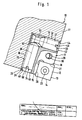
- the cutting tool 10 has a base body 11 which e.g. has a plurality of individual cutting plates 12 which are attached to the base body 11 in an adjustable and lockable manner.
- a base body 11 which e.g. has a plurality of individual cutting plates 12 which are attached to the base body 11 in an adjustable and lockable manner.
- only one insert 12 can be seen, which is approximately square in this case, with cutters 13-16 being formed on all four sides, so that the insert 12 can be placed as a so-called indexable insert, so that one or the other other cutting edge 13 - 16 is effective for machining.
- the cutting plate 12 is fastened to its own plate holder 17, also referred to as a cassette.
- the plate holder 17 is approximately rectangular and for this purpose is provided in the area of a corner with a step-like recessed seat 18, which has a base 19 and two to each other, e.g. has right-angled side surfaces 20 and 21.
- the insert 12 placed in the seat 18 thus lies flat with its back surface against the base surface 19 and with two sides against the side surfaces 20 and 21, so that a defined and firm fit is ensured.
- the plate holder 17 contains a threaded bore 22 into which a fastening screw 23, e.g. Torx screw is screwed in, which passes through the cutting plate 12 and can be received sunk therein with its head.
- the plate holder 17 is in turn adjustable and fixable in an assigned and suitable seat 24 of the base body 11, as is known in such cutting tools 10. Details of the seat 24 in Base body 11 therefore need no special description.
- the seat 24 has a base surface 25 and two lateral support surfaces 26 and 27, for example extending approximately at right angles to one another and projecting from the base surface 25, which are, for example, flat.
- In the area of the seat 24 there is an oblique through hole 28 through which a clamping screw 29 can reach from the rear, which then engage from the rear of the plate holder 17 into a threaded hole 30 contained in the latter and thus firmly tighten the plate holder 17 with its back when tightened can attract the base surface 25 and also in the transverse direction against the support surfaces 26, 27.
- the threaded bore 30 in the plate holder 17 has the same oblique course as the through hole 28.
- the latter can be provided on the side facing away from the plate holder 17 with a depression 31 for receiving the head 32 of the clamping screw 29. Due to this rear fastening of the plate holder 17 in the seat 24, the head 32 of the clamping screw 29 is not in the chest area and where the chips are produced during the machining operation. The head 32 is thereby protected against damage and clogging of its tool engagement surface with chips or the like. protected.
- this rear attachment via the threaded bore 30 in the plate holder 17 has the advantage that the plate holder 17 can be kept smaller; because the through hole 28, for example, larger for this fastening by means of the clamping screw 29 and the depression 31 intended for receiving the head 32 are located in the base body 11 and not in the plate holder 17, which otherwise requires more space in the plate holder 17 and in a larger construction of the plate holder 17 for these reasons alone.
- the plate holder 17 (cassette) for fastening the cutting plate 12 is omitted.
- the cutting plate 12 is accommodated directly in a seat of the base body 11 corresponding to its size, analogous to the illustrated holding of the plate holder 17 in the seat 24.
- the cutting plate 12 is either fastened directly by means of a fastening screw 23 which engages in a threaded bore in the base body 11, or a clamping plate is provided which is supported on the base body 11 and is clamped thereon with a fastening screw and presses on the cutting plate 12 and presses it into it Holds seat in the base body 11.
- Such attachments of the cutting plate 12 directly in an associated seat in the base body 11 are known per se. These are also within the scope of the invention - even if further details are explained using the example of fastening by means of the plate holder 17 shown.
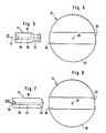
- the cutting tool 10 has two bolt-shaped eccentrics 33 and 34 which are directed transversely to one another, in particular are approximately at right angles to one another.
- Each eccentric 33, 34 can be rotated about its longitudinal axis 35 or 36 and is supported on the one hand on the base body 11 and on the other hand on the plate holder 17. It is understood that in the mentioned embodiment, not shown, in which each insert 12 is held directly in an associated seat in the base body 11, each eccentric 33, 34 then, instead of the insert holder 17, rests directly on the side of the insert 12, so that these is supported on the base body 11 via the respective eccentric 33, 34.
- eccentric includes every possible configuration in such a way that the rotational distance of the outer circumferential surface 37 or 38 from the longitudinal axis 35 or 36 increases or decreases in one direction or the other when rotating about the longitudinal axis 35 or 36.
- the eccentricity can already be achieved, for example, by flattening 39 or 40 of the peripheral surface 37 or 38.
- the eccentricity can be realized in that the outer peripheral surface 37 or 38 of each eccentric 33 or 34 follows, for example, a spiral, as is made visible in FIGS. 6 and 8 by the enlarged illustration.
- the envelope circle is shown in dash-dot lines.
- One eccentric 33 is supported within an associated receptacle 41 on the upper edge region of the plate holder 17 in FIGS. 1 and 2.
- the receptacle 41 is designed, for example, as a bore 42 which runs continuously, the wall 43 of which points towards the support surface 27 a continuous slot 44 is opened such that the associated eccentric 33 can protrude with a peripheral part through the slot 44 to the outside and can rest on the support surface 27.
- the other eccentric 34 is also mounted in the plate holder 17 in an associated receptacle 45, which is designed as a bore 46, a continuous slot 48 being contained in the wall 47, which faces the support surface 26, through which the bore 46 to the support surface 26 is opened in such a way that the associated eccentric 34 can protrude with a peripheral part through the slot 48 to the outside and can rest on the support surface 26.
- the width of each slot 44 and 48 is smaller than 180 ° circumferential angle and selected so that the eccentric 33 or 34 received therein is held captively in the direction transverse to the bore 42 or 46.
- the respective slot 44 or 48 is provided on the edge area associated with the support surface 27 or 26, it is ensured that the respective eccentric 33 or 34 is supported on at least part of its length with a part protruding and protruding from the bore 42 or 46 on this support surface 27 or 26 of the base body 11.
- the respective eccentric 33 or 34 is in contact with the inner circumferential surface of the bore 42 or 46, so that the forces acting on the plate holder 17 from the outside are absorbed and supported and via the respective eccentric 33 or 34 be passed to the base body 11.
- Both eccentrics 33, 34 run e.g. approximately at right angles to each other.
- one of the eccentrics 33, e.g. axial adjustment and the other eccentric 34 which e.g. radial adjustment of the plate holder 17 - and thus also the cutting plate 12 - serve.
- Each bolt-shaped eccentric 33, 34 is at one end, which is accessible from the outside, with a tool engagement surface 49 or 50, e.g. provided with a slot on which a suitable tool, e.g. a screwdriver that can attack.
- the clamping screw 29 does not need to be loosened, but it can be inserted into the slot 49 of the eccentric 33, for example with a screwdriver and this is rotated in a corresponding, sensible manner about its longitudinal axis 35, with, for example, increasing eccentricity of its outer circumferential surface 37 with respect to the longitudinal axis 35.
- the plate holder 17 together with the cutting plate 12 fixed thereon is displaced along the support surface 26. Because of the effective self-locking Eccentric 33 prevented from adjusting itself in an undesired manner about its longitudinal axis 35, so that the setting made is retained.
- each support surface 26, 27 of the base body 11, which is assigned to the eccentric 34 or 33 is designed as a flat surface.
- this support surface 26, 27 can also be designed as an arcuate, recessed groove, for example.
- each eccentric 33, 34, as described for the plate holder 17 shown can be stored within a receptacle, for example a bore, which instead of in the plate holder 17 in the base body 11 and there in the region of the support surfaces 26 , 27 is provided. Then this hole expediently contains a continuous slot through which the eccentric 33, 34 received therein can protrude in the direction of the plate holder 17.
- the plate holder 17 is simplified since it does not contain any bores 42, 46 for the eccentrics 33, 34, because these bores are displaced into the base body 11.
- This exemplary embodiment described, not shown, is therefore in principle the same arrangement, in which only one exchange is made.
- the plate holder 17 is also omitted for this exemplary embodiment (not shown) and the cutting plate 12 can be fastened directly in an assigned seat in the base body 11, the eccentrics 33, 34 in the bores of the base body 11 then being located directly on the assigned sides of the base plate 11 Fit cutting plate 12 and support it directly on base body 11.
- the two eccentrics 33, 34 abut each other with one end and thereby engage in a form-fitting manner.
- Both eccentrics 33, 34 together form a captive holder for one of the two eccentrics, in the exemplary embodiment shown for the eccentric 33 located at the top in FIG. 1.
- This eccentric 33 has an expediently circumferential groove 51 at one end, which lies opposite the tool engagement surface 49 provided, in which an end portion 52 of the other eccentric 34 engages in the butt region with positive locking of the eccentric 33 in the direction of its longitudinal axis 35.
- the groove 51 is approximately V-shaped in cross section. Instead, it can also be approximately U-shaped or approximately arc-shaped.
- the end section 52 of the eccentric 34 tapers towards the free end. It can be designed to match the cross section of the groove 51. In the exemplary embodiment shown, the end section 52 is approximately frustoconical. It can be advantageous if the end section 52 is essentially of the same shape as the cross section of the groove 51.
- the arrangement is such that the one eccentric 33, which contains the groove 51, with respect to a longitudinal center axis of the base body 11, not shown, e.g. is directed approximately radially and is held captively against the centrifugal force effect during the rotation of the cutting tool 10 by means of the other eccentric 34. In individual cases, this depends on the detailed design of the respective cutting tool 10.
Landscapes
- Engineering & Computer Science (AREA)
- Mechanical Engineering (AREA)
- Auxiliary Devices For Machine Tools (AREA)
- Milling Processes (AREA)
- Cutting Tools, Boring Holders, And Turrets (AREA)
- Drilling Tools (AREA)
Claims (16)
- Outil d'usinage par enlèvement de copeaux, comprenant un corps de base (11) dans lequel est disposée au moins une plaquette de coupe (12) pouvant être réglée directement ou indirectement - par l'intermédiaire d'un support de plaquette (17) - qui est maintenue dans une direction ainsi que dans une deuxième direction orientée transversalement par rapport à cette dernière, sur respectivement un excentrique (33, 34) lequel s'appuie à son tour sur le corps de base (11) et peut être tourné autour de son axe longitudinal (35 et respectivement 36), caractérisé en ce qu'un excentrique (33) présente à l'une de ses extrémités une rainure circulaire (51) dans laquelle s'engage, dans la zone de contact, une section terminale (52) de l'autre excentrique (34), avec blocage à engagement positif de l'excentrique (33) dans le sens de son axe longitudinal (35), de sorte que les deux excentriques (33, 34) se touchent avec respectivement une extrémité et s'emboîtent à engagement positif.
- Outil d'usinage par enlèvement de copeaux selon la revendication 1, caractérisé en ce que les deux excentriques (33, 34) forment ensemble une fixation imperdable.
- Outil d'usinage par enlèvement de copeaux selon la revendication 1, caractérisé en ce que la section transversale de la rainure (51) présente sensiblement une forme en U ou en V.
- Outil d'usinage par enlèvement de copeaux selon l'une des revendications 1 ou 3, caractérisé en ce que la section terminale (52) de l'autre excentrique (34) se rétrécit en direction de l'extrémité libre.
- Outil d'usinage par enlèvement de copeaux selon l'une des revendications 1 à 4, caractérisé en ce que la section terminale (52) de l'autre excentrique (34) présente sensiblement une forme tronconique.
- Outil d'usinage par enlèvement de copeaux selon l'une des revendications 1 à 5, caractérisé en ce que la section terminale (52) de l'autre excentrique (34) présente sensiblement la même forme que la section transversale de la rainure (51).
- Outil d'usinage par enlèvement de copeaux selon l'une des revendications 1 à 6, caractérisé en ce que, dans le sens circonférentiel, une section longitudinale essentielle d'au moins l'un des excentriques (33, 34), suit sensiblement une spirale avec sa surface extérieure (37 et respectivement 38), créant ainsi l'excentricité.
- Outil d'usinage par enlèvement de copeaux selon l'une des revendications 1 à 7, caractérisé en ce que les excentriques (31, 34) sont conformés en boulons dont l'extrémité opposée à la zone de contact est munie d'une surface d'attaque (49 et respectivement 50) pour la mise en place d'un outil.
- Outil d'usinage par enlèvement de copeaux selon l'une des revendications 1 à 8, caractérisé en ce qu'au moins l'un des deux excentriques (33, 34) présente sur sa surface extérieure (37 et respectivement 38) un méplat (39 et respectivement 40).
- Outil d'usinage par enlèvement de copeaux selon l'une des revendications 1 à 9, caractérisé en ce que chaque excentrique (33, 34) est placé à l'intérieur d'un logement associé du corps de base (11), par exemple dans un alésage, et maintient sur au moins une partie de sa longueur la plaquette de coupe (12) ou un support de plaquette (17) portant une plaquette de coupe (12) qui y est appliqué.
- Outil d'usinage par enlèvement de copeaux selon l'une des revendications 1 à 10, caractérisé en ce que chaque excentrique (33, 34) est placé à l'intérieur d'un logement associé (41 et respectivement 45) d'un support de plaquette (17) portant une plaquette de coupe (12), et maintenu sur au moins une partie de sa longueur, avec une partie dépassant du logement (41 et respectivement 45), sur une surface d'appui (27 et respectivement 26) du corps de base (11), par exemple à l'intérieur d'un logement associé.
- Outil d'usinage par enlèvement de copeaux selon la revendication 11, caractérisé en ce que le logement (41, 45) du support de plaquette (17) est réalisé pour chaque excentrique (33 et respectivement 34) sous la forme d'un alésage (42 et respectivement 46) dont la paroi (43 et respectivement 47) est ouverte sur l'un des côtés qui est tourné vers la surface d'appui (27 et respectivement 26) du corps de base (11), par l'intermédiaire d'une fente continue (44 et respectivement 48), de telle façon que l'excentrique associé (33 et respectivement 34) peut dépasser vers l'extérieur, au travers de ladite fente (44 et respectivement 48), avec un élément périphérique.
- Outil d'usinage par enlèvement de copeaux selon la revendication 12, caractérisé en ce que la largeur de chacune des fentes (44 et respectivement 48) est inférieure à un angle périphérique de 180° et choisie de telle façon que l'excentrique associé (33 et respectivement 34) est maintenu de manière imperdable dans ladite fente, transversalement par rapport à l'alésage (42 et respectivement 46).
- Outil d'usinage par enlèvement de copeaux selon l'une des revendications 1 à 13, caractérisé en ce que le support de plaquette (17) qui porte une plaquette de coupe (12) comporte, à distance du siège (18) pour la plaquette de coupe (12), un taraudage (30) de préférence incliné dans lequel s'engage une vis de serrage (29) pour la fixation du support de plaquette (17) sur le siège (24) du corps de base (11), ladite vis de serrage traversant un alésage de passage (28) dans le corps de base (11).
- Outil d'usinage par enlèvement de copeaux selon la revendication 14, caractérisé en ce que la vis de serrage (29) s'engage à partir de la face arrière du support de plaquette (17) dans le taraudage (30) de celui-ci.
- Outil d'usinage par enlèvement de copeaux selon l'une des revendications 1 à 15, caractérisé en ce que les deux excentriques (33, 34) s'étendent sensiblement orthogonalement l'un par rapport à l'autre, et que l'un des excentriques (33) comprenant la rainure (51) est orienté sensiblement dans le sens radial par rapport à l'axe longitudinal médian du corps de base (11) et maintenu de manière imperdable au moyen de l'autre excentrique (34), contre l'action de la force centrifuge, et sert par exemple au réglage axial, tandis que l'autre excentrique (34) assure par exemple le réglage radial.
Priority Applications (1)
| Application Number | Priority Date | Filing Date | Title |
|---|---|---|---|
| AT90111502T ATE93429T1 (de) | 1989-07-26 | 1990-06-19 | Zerspanungswerkzeug. |
Applications Claiming Priority (2)
| Application Number | Priority Date | Filing Date | Title |
|---|---|---|---|
| DE8909060U DE8909060U1 (de) | 1989-07-26 | 1989-07-26 | Zerspanungswerkzeug |
| DE8909060U | 1989-07-26 |
Publications (3)
| Publication Number | Publication Date |
|---|---|
| EP0410129A2 EP0410129A2 (fr) | 1991-01-30 |
| EP0410129A3 EP0410129A3 (en) | 1991-05-08 |
| EP0410129B1 true EP0410129B1 (fr) | 1993-08-25 |
Family
ID=6841435
Family Applications (1)
| Application Number | Title | Priority Date | Filing Date |
|---|---|---|---|
| EP90111502A Expired - Lifetime EP0410129B1 (fr) | 1989-07-26 | 1990-06-19 | Outil de coupe |
Country Status (3)
| Country | Link |
|---|---|
| EP (1) | EP0410129B1 (fr) |
| AT (1) | ATE93429T1 (fr) |
| DE (2) | DE8909060U1 (fr) |
Families Citing this family (3)
| Publication number | Priority date | Publication date | Assignee | Title |
|---|---|---|---|---|
| IL196440A (en) * | 2009-01-11 | 2012-03-29 | Iscar Ltd | Adjustment mechanism |
| CN110000428B (zh) * | 2019-03-29 | 2024-01-05 | 太仓瑞鼎精密机械科技有限公司 | 机夹刀片式可调铰刀 |
| JP7192186B1 (ja) * | 2022-01-26 | 2022-12-20 | 住友電工ハードメタル株式会社 | 切削工具 |
Family Cites Families (4)
| Publication number | Priority date | Publication date | Assignee | Title |
|---|---|---|---|---|
| FR2140723A5 (fr) * | 1971-03-25 | 1973-01-19 | Garih Claude | |
| DD209347A3 (de) * | 1981-12-28 | 1984-04-25 | Schmalkalden Werkzeug | Planfraeskopf mit einstellbarer planschlichtschneide |
| DE3530745A1 (de) * | 1985-08-28 | 1987-03-05 | Kieninger Walter Gmbh | Messerkopf |
| DE3838816A1 (de) * | 1988-11-17 | 1990-05-23 | Feldmuehle Ag | Schneidwerkzeug fuer die spanabhebende bearbeitung |
-
1989
- 1989-07-26 DE DE8909060U patent/DE8909060U1/de not_active Expired
-
1990
- 1990-06-19 DE DE90111502T patent/DE59002455D1/de not_active Expired - Fee Related
- 1990-06-19 AT AT90111502T patent/ATE93429T1/de not_active IP Right Cessation
- 1990-06-19 EP EP90111502A patent/EP0410129B1/fr not_active Expired - Lifetime
Also Published As
| Publication number | Publication date |
|---|---|
| EP0410129A2 (fr) | 1991-01-30 |
| EP0410129A3 (en) | 1991-05-08 |
| ATE93429T1 (de) | 1993-09-15 |
| DE8909060U1 (de) | 1989-09-07 |
| DE59002455D1 (de) | 1993-09-30 |
Similar Documents
| Publication | Publication Date | Title |
|---|---|---|
| EP0282090B1 (fr) | Fraise à plaquettes | |
| EP0674560B1 (fr) | Outil de forage a piece de coupe rapportee interchangeable | |
| DE19624685C1 (de) | Rundstabmesser und insbesondere dafür vorgesehener Messerkopf | |
| EP0884124B1 (fr) | Fraise avec ajustement axial | |
| EP2379268B1 (fr) | Alésoir, plaquettes de coupe pour cet alésoir et procédé de réglage du diamètre d'usinage de cet alésoir | |
| EP0472563B1 (fr) | Outil a magasin interchangeable deplacable | |
| EP0325212B1 (fr) | Tête de fraisage | |
| EP0995528A2 (fr) | Fraise avec des plaquettes de coupe indexables | |
| EP1140400B1 (fr) | Outil a enlevement de copeaux pour usinage a vitesse elevee | |
| EP1136158A1 (fr) | Porte plaquette de coupe et plaquette du rainurage | |
| DE69709741T2 (de) | Schneidwerkzeug und spannbolzen | |
| DE4101438A1 (de) | Spindeladapter fuer werkzeughalter mit werkzeugeinstellsteuerung | |
| DE3875615T2 (de) | Schneidwerkzeughalter. | |
| DE2300169A1 (de) | Einstellbarer werkzeughalter | |
| EP0410104B1 (fr) | Outil d'usinage par enlèvement de copeaux | |
| DE3333495A1 (de) | Drehbares zerspanungswerkzeug, insbesondere ausbohrkopf od. dgl. | |
| DE10250040B4 (de) | Reibahlen-Schneidwerkzeug, Reibahle und Verfahren zum Befestigen eines Schneidwerkzeugs | |
| EP1885517B1 (fr) | Porte-outil a reglage precis | |
| DE2522565B2 (de) | Tiefbohrwerkzeug | |
| EP0860227A1 (fr) | Fraise pour surfaces planes ou coins | |
| EP1136162A1 (fr) | Fraise à surfacer et à fraise des coins | |
| EP0410129B1 (fr) | Outil de coupe | |
| EP0693013B1 (fr) | Systeme modulaire d'outil | |
| EP0175011B1 (fr) | Outil de coupe rotatif en particulier tête de foreuse | |
| DE10108103B4 (de) | Maschinenwerkzeug mit verstellbarer Schneidplatte |
Legal Events
| Date | Code | Title | Description |
|---|---|---|---|
| PUAI | Public reference made under article 153(3) epc to a published international application that has entered the european phase |
Free format text: ORIGINAL CODE: 0009012 |
|
| AK | Designated contracting states |
Kind code of ref document: A2 Designated state(s): AT CH DE FR GB IT LI NL SE |
|
| PUAL | Search report despatched |
Free format text: ORIGINAL CODE: 0009013 |
|
| AK | Designated contracting states |
Kind code of ref document: A3 Designated state(s): AT CH DE FR GB IT LI NL SE |
|
| 17P | Request for examination filed |
Effective date: 19910701 |
|
| 17Q | First examination report despatched |
Effective date: 19921126 |
|
| GRAA | (expected) grant |
Free format text: ORIGINAL CODE: 0009210 |
|
| AK | Designated contracting states |
Kind code of ref document: B1 Designated state(s): AT CH DE FR GB IT LI NL SE |
|
| REF | Corresponds to: |
Ref document number: 93429 Country of ref document: AT Date of ref document: 19930915 Kind code of ref document: T |
|
| ET | Fr: translation filed | ||
| REF | Corresponds to: |
Ref document number: 59002455 Country of ref document: DE Date of ref document: 19930930 |
|
| GBT | Gb: translation of ep patent filed (gb section 77(6)(a)/1977) |
Effective date: 19930917 |
|
| ITF | It: translation for a ep patent filed | ||
| PLBE | No opposition filed within time limit |
Free format text: ORIGINAL CODE: 0009261 |
|
| STAA | Information on the status of an ep patent application or granted ep patent |
Free format text: STATUS: NO OPPOSITION FILED WITHIN TIME LIMIT |
|
| 26N | No opposition filed | ||
| EAL | Se: european patent in force in sweden |
Ref document number: 90111502.2 |
|
| REG | Reference to a national code |
Ref country code: GB Ref legal event code: 746 Effective date: 20000502 |
|
| REG | Reference to a national code |
Ref country code: FR Ref legal event code: D6 |
|
| REG | Reference to a national code |
Ref country code: GB Ref legal event code: IF02 |
|
| PGFP | Annual fee paid to national office [announced via postgrant information from national office to epo] |
Ref country code: GB Payment date: 20020527 Year of fee payment: 13 |
|
| PGFP | Annual fee paid to national office [announced via postgrant information from national office to epo] |
Ref country code: NL Payment date: 20020617 Year of fee payment: 13 Ref country code: FR Payment date: 20020617 Year of fee payment: 13 |
|
| PGFP | Annual fee paid to national office [announced via postgrant information from national office to epo] |
Ref country code: AT Payment date: 20020620 Year of fee payment: 13 |
|
| PGFP | Annual fee paid to national office [announced via postgrant information from national office to epo] |
Ref country code: CH Payment date: 20020621 Year of fee payment: 13 |
|
| PGFP | Annual fee paid to national office [announced via postgrant information from national office to epo] |
Ref country code: SE Payment date: 20020624 Year of fee payment: 13 |
|
| PG25 | Lapsed in a contracting state [announced via postgrant information from national office to epo] |
Ref country code: GB Free format text: LAPSE BECAUSE OF NON-PAYMENT OF DUE FEES Effective date: 20030619 Ref country code: AT Free format text: LAPSE BECAUSE OF NON-PAYMENT OF DUE FEES Effective date: 20030619 |
|
| PG25 | Lapsed in a contracting state [announced via postgrant information from national office to epo] |
Ref country code: SE Free format text: LAPSE BECAUSE OF NON-PAYMENT OF DUE FEES Effective date: 20030620 |
|
| PG25 | Lapsed in a contracting state [announced via postgrant information from national office to epo] |
Ref country code: LI Free format text: LAPSE BECAUSE OF NON-PAYMENT OF DUE FEES Effective date: 20030630 Ref country code: CH Free format text: LAPSE BECAUSE OF NON-PAYMENT OF DUE FEES Effective date: 20030630 |
|
| PG25 | Lapsed in a contracting state [announced via postgrant information from national office to epo] |
Ref country code: NL Free format text: LAPSE BECAUSE OF NON-PAYMENT OF DUE FEES Effective date: 20040101 |
|
| EUG | Se: european patent has lapsed | ||
| GBPC | Gb: european patent ceased through non-payment of renewal fee |
Effective date: 20030619 |
|
| REG | Reference to a national code |
Ref country code: CH Ref legal event code: PL |
|
| PG25 | Lapsed in a contracting state [announced via postgrant information from national office to epo] |
Ref country code: FR Free format text: LAPSE BECAUSE OF NON-PAYMENT OF DUE FEES Effective date: 20040227 |
|
| NLV4 | Nl: lapsed or anulled due to non-payment of the annual fee |
Effective date: 20040101 |
|
| REG | Reference to a national code |
Ref country code: FR Ref legal event code: ST |
|
| PGFP | Annual fee paid to national office [announced via postgrant information from national office to epo] |
Ref country code: DE Payment date: 20040825 Year of fee payment: 15 |
|
| PG25 | Lapsed in a contracting state [announced via postgrant information from national office to epo] |
Ref country code: IT Free format text: LAPSE BECAUSE OF NON-PAYMENT OF DUE FEES Effective date: 20050619 |
|
| PG25 | Lapsed in a contracting state [announced via postgrant information from national office to epo] |
Ref country code: DE Free format text: LAPSE BECAUSE OF NON-PAYMENT OF DUE FEES Effective date: 20060103 |