EP0325745A2 - Dispositif pour l'indication de position de commutation d'un sectionneur de coupure en charge multiposition - Google Patents
Dispositif pour l'indication de position de commutation d'un sectionneur de coupure en charge multiposition Download PDFInfo
- Publication number
- EP0325745A2 EP0325745A2 EP88120544A EP88120544A EP0325745A2 EP 0325745 A2 EP0325745 A2 EP 0325745A2 EP 88120544 A EP88120544 A EP 88120544A EP 88120544 A EP88120544 A EP 88120544A EP 0325745 A2 EP0325745 A2 EP 0325745A2
- Authority
- EP
- European Patent Office
- Prior art keywords
- switch
- openings
- colored areas
- plug
- drive
- Prior art date
- Legal status (The legal status is an assumption and is not a legal conclusion. Google has not performed a legal analysis and makes no representation as to the accuracy of the status listed.)
- Ceased
Links
Images

Classifications
-
- H—ELECTRICITY
- H01—ELECTRIC ELEMENTS
- H01H—ELECTRIC SWITCHES; RELAYS; SELECTORS; EMERGENCY PROTECTIVE DEVICES
- H01H9/00—Details of switching devices, not covered by groups H01H1/00 - H01H7/00
- H01H9/16—Indicators for switching condition, e.g. "on" or "off"
Definitions
- the invention relates to a device for displaying the switching position of multi-position switch disconnectors, in particular 3-position switch disconnectors in an SF6-encapsulated switch disconnector, as specified in the preamble of claim 1.
- the object of the invention is to provide a position indicator coupled to the switch while avoiding movable intermediate members, which ensures a correct, clear and easily recognizable display even with certain positional deviations in the end positions.
- this switch position indicator can be carried out inexpensively, is very clear and can be easily integrated into a mimic diagram showing the structure of the switchgear.
- the avoidance of any moving intermediate elements between the switch and the display unit leads to a high level of display security, which is particularly important in systems without visible separation distances.
- Fig. 1 shows an axial section of the basic structure of a spring-loaded actuator 1 of a switch disconnector.
- the detailed structure of this spring-loaded actuator plays practically no role in connection with the present invention, so that it is not dealt with in detail, but rather reference is made to patent application P 36 26 526.8, in which details are explained.
- FIG. 1 shows a switch shaft 2 which is connected in a rotationally fixed manner to a carrier shaft 3 designed as a cup shaft.
- a central plug-in receiving part 4 is inserted and fixed. This part serves to receive one of the two plug pins 6, 7 of the indicated plug lever 5 for switch actuation.
- the drive pin 7, which is spaced apart from the central plug pin 6, engages in an eccentrically arranged driver 9, which is designed in the form of an elongated hole receptacle, in order to ensure the use of different levers for the switch-on process and the grounding process in connection with the corresponding guide slots in the front plate 10.
- a disc 16 which provides a switch position indicator, is fixedly connected to the plug-in receptacle part 4 directly or via carrier elements.
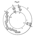
- the pane 16 shown in FIG. 1 and located immediately behind the front plate 10 is provided with color areas 21 in a very defined manner, as shown in FIG. 2.
- the colored areas 21 are selected in this example so that the disk is suitable for a transformer switch with double grounding.
- These ring-segment-shaped colored areas 21 are positioned on the disk 16 so that, in cooperation with four cross-shaped openings in the front panel, depending on the respective switch position, these cross-shaped openings are deposited in pairs in such a way that the corresponding wiring of a mimic diagram for signaling the Passage position supplemented or interrupted to signal the locked position and a crossbar is formed for this purpose.
- the openings in the front panel are defined in terms of their dimensions and their position, but the colored areas 21 are not exactly adapted to the size of these openings, but are chosen to be larger in their extension, so that an exact, clear and full-area depositing of the corresponding opening is also ensured , if there is a certain positional deviation in the respective end positions of the switch position, which can easily be about 2 °.
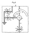
- FIG 3 shows a section of a mimic diagram attached to the front plate 10, specifically for a switch with double grounding.
- the plug lever used for the switch actuation there are recesses for the plug lever used for the switch actuation, namely a central recess for the receiving bearing 8, into which the central plug 6 of the plug lever 5 is inserted, and partially annular recesses 11, 12 within which the drive pin 7 can move, with which the driver 9 can be coupled.
- the driver 9 In the position shown, the driver 9 is in the grounding position.
- This switching state is also represented by the mimic diagram, which comprises three signaling units 13. These signaling units 13 are located in line trenches 14 of the mimic diagram and make it clear whether the corresponding line set is switched through or blocked.
- each signaling unit 13 in the front plate 10 has four cross-shaped openings 17, 18, 19, 20, the pair of openings 17, 18 being aligned with the respective line 14 and the pair of openings 19, 20 being perpendicular to the respective line 14.
- the central region 15 between the openings 17, 18, 19, 20 preferably has a cross shape and a coloring corresponding to the cable gaps.
- the disc 16 provided with the colored areas 21, which is pivoted together with the switch shaft 2.
- the colored areas reach behind the openings 17, 18, 19, 20 in the signaling units 13 in such a way that the blind circuit diagram is supplemented in accordance with the actual switching state.
- the switch is in the grounding position, and accordingly the openings 17 and 18 are deposited by the colored areas of the disk 16 and the mimic diagram thus signals correspondingly grounded cable runs.
- the signaling unit 13 assigned to the incoming cable run must indicate the state of the interruption, which is also the case.
Landscapes
- Switch Cases, Indication, And Locking (AREA)
- Train Traffic Observation, Control, And Security (AREA)
Applications Claiming Priority (2)
| Application Number | Priority Date | Filing Date | Title |
|---|---|---|---|
| DE19883802207 DE3802207A1 (de) | 1988-01-26 | 1988-01-26 | Vorrichtung zur anzeige der schaltstellung von mehrstellungs-lasttrennschaltern |
| DE3802207 | 1988-01-26 |
Publications (2)
| Publication Number | Publication Date |
|---|---|
| EP0325745A2 true EP0325745A2 (fr) | 1989-08-02 |
| EP0325745A3 EP0325745A3 (fr) | 1990-08-29 |
Family
ID=6345998
Family Applications (1)
| Application Number | Title | Priority Date | Filing Date |
|---|---|---|---|
| EP88120544A Ceased EP0325745A3 (fr) | 1988-01-26 | 1988-12-08 | Dispositif pour l'indication de position de commutation d'un sectionneur de coupure en charge multiposition |
Country Status (2)
| Country | Link |
|---|---|
| EP (1) | EP0325745A3 (fr) |
| DE (1) | DE3802207A1 (fr) |
Cited By (1)
| Publication number | Priority date | Publication date | Assignee | Title |
|---|---|---|---|---|
| EP1850357A3 (fr) * | 2006-04-25 | 2008-05-07 | AREVA Energietechnik GmbH | Indication de position pour installation de commutation électrique |
Families Citing this family (1)
| Publication number | Priority date | Publication date | Assignee | Title |
|---|---|---|---|---|
| DE202006012002U1 (de) * | 2006-08-03 | 2007-12-20 | Walter Kraus Gmbh | Antrieb für einen Schalter in Elektroanlagen |
Family Cites Families (3)
| Publication number | Priority date | Publication date | Assignee | Title |
|---|---|---|---|---|
| DE1107323B (de) * | 1960-07-23 | 1961-05-25 | Calor Emag Elektrizitaets Ag | Stellungsanzeiger fuer elektrische Schaltanlagen mit ausfahrbarem Schaltgeraet |
| GB1072112A (en) * | 1963-01-03 | 1967-06-14 | Ass Elect Ind | Improved electric switch |
| DE3626526A1 (de) * | 1986-08-05 | 1988-02-11 | Concordia Sprecher Schalt | Federspeicher-antrieb fuer elektrische schaltgeraete |
-
1988
- 1988-01-26 DE DE19883802207 patent/DE3802207A1/de not_active Withdrawn
- 1988-12-08 EP EP88120544A patent/EP0325745A3/fr not_active Ceased
Cited By (1)
| Publication number | Priority date | Publication date | Assignee | Title |
|---|---|---|---|---|
| EP1850357A3 (fr) * | 2006-04-25 | 2008-05-07 | AREVA Energietechnik GmbH | Indication de position pour installation de commutation électrique |
Also Published As
| Publication number | Publication date |
|---|---|
| EP0325745A3 (fr) | 1990-08-29 |
| DE3802207A1 (de) | 1989-07-27 |
Similar Documents
| Publication | Publication Date | Title |
|---|---|---|
| EP2446453B1 (fr) | Fenêtre de visualisation et borne de terre pour ensemble de haute tension | |
| DE2341982C2 (de) | Kunststoffisolierter Schaltblock für Hochspannungsschaltanlagen | |
| EP0491260B1 (fr) | Dispositif de câblage | |
| DE4140587A1 (de) | Elektronische steuereinrichtung zum schalten mehrerer elektrischer lasten | |
| DE2414200A1 (de) | Metallumschlossene schaltanlage fuer hohe spannung mit in einem ring in reihe geschalteten schaltfeldern | |
| EP0249166B1 (fr) | Commutateur de commande d'un moteur d'essuie-glace | |
| DE2646393C3 (de) | Anzeigesystem für ein Stufenwechselgetriebe, insbesondere für Kraftfahrzeuge | |
| DE3515203A1 (de) | Gekapselter lastschalter | |
| AT405581B (de) | Stufenwähler für stufenschalter an stufentransformatoren | |
| EP0325745A2 (fr) | Dispositif pour l'indication de position de commutation d'un sectionneur de coupure en charge multiposition | |
| DE855129C (de) | Schalter und Abschwaecher | |
| DE2816262C2 (de) | Schaltmatrix für die Durchschaltung von Wechselstromsignalen | |
| DE69413163T2 (de) | Vierpoliger Differentialschutzschalter | |
| DE4129295C1 (fr) | ||
| DE29806211U1 (de) | Kapselungsbaustein für eine Hochspannungsschaltanlage | |
| EP0134585A1 (fr) | Dispositif de commande à commutateur multi-coordonnées, destiné à commander un clavier | |
| DE4301022C2 (de) | Einrichtung mit einem pneumatisch oder hydraulisch betätigbaren elektrischen Schalter sowie einen pneumatischen oder hydraulischen Druck- oder Differenzdruckschalter und einen Anschlußstecker für eine derartige Einrichtung | |
| DE2923019A1 (de) | Hochspannungsschalter | |
| EP0474085B1 (fr) | Multimètre pour mesurer différentes grandeurs selon le choix | |
| EP0391339B1 (fr) | Appareil de couplage haute tension | |
| EP0601462A1 (fr) | Commutateur, notamment commutateur fixé à la colonne de direction | |
| DE2847376C2 (de) | Ein- oder mehrpolige Trennschalteranordnung für gekapselte Schaltanlagen | |
| DE2358885B2 (de) | Stufenwähler für mit einer einen Grob- und Feinstufenteil enthaltenden Stufenwicklung ausgestattete Transformatoren | |
| DE534656C (de) | Selbsttaetige, abhaengig von der Betriebsspannung arbeitende Parallelschalteinrichtung | |
| EP0521180B1 (fr) | Dispositifs de signalisation des risques en boucle |
Legal Events
| Date | Code | Title | Description |
|---|---|---|---|
| PUAI | Public reference made under article 153(3) epc to a published international application that has entered the european phase |
Free format text: ORIGINAL CODE: 0009012 |
|
| AK | Designated contracting states |
Kind code of ref document: A2 Designated state(s): AT CH DE ES FR LI |
|
| PUAL | Search report despatched |
Free format text: ORIGINAL CODE: 0009013 |
|
| AK | Designated contracting states |
Kind code of ref document: A3 Designated state(s): AT CH DE ES FR LI |
|
| 17P | Request for examination filed |
Effective date: 19901025 |
|
| 17Q | First examination report despatched |
Effective date: 19931004 |
|
| RAP1 | Party data changed (applicant data changed or rights of an application transferred) |
Owner name: GEC ALSTHOM T & D GMBH |
|
| STAA | Information on the status of an ep patent application or granted ep patent |
Free format text: STATUS: THE APPLICATION HAS BEEN REFUSED |
|
| 18R | Application refused |
Effective date: 19941030 |